
 ?Mathematical formulae have been encoded as MathML and are displayed in this HTML version using MathJax in order to improve their display. Uncheck the box to turn MathJax off. This feature requires Javascript. Click on a formula to zoom.
Abstract
The calculation of short circuit (SC) current has to be accurate because of their importance in power protection system’s design and to determine the capacity of the protective devices. Therefore, there are many standards and programs to estimate SC calculation. The aim of this paper is to provide further calculation methods’ understanding for determining SC current in PSS/E program. Here, the characteristics of SC at the busbars of Al-Nassiriya power plant; with 400/132 KV local transformers; which is part of Iraqi power system is analyzed using PSS/E program methods such as automatic sequence fault calculation (ASCC), IEC 60909 and (ANSI) standards. The finding of results comparison between the three methods refers that IEC standard result was the most accurate one in subtransient current calculation. This paper concludes that IEC have the best method to be followed in subtransient current calculations for Iraq power grid expansion studies and planning.
PUBLIC INTEREST STATEMENT
Calculating short-circuit current level is important for electrical power engineers to renew protection devices and assess stability. Several criteria have emerged to study fault current such as ASCC, IEC, and ANSI.
The electrical systems expansion and the calculation accuracy importance require the development of calculation programs to study the system performance explicitly. One of these programs is the PSS®E, which deals with all the criteria, taking into account the factors affecting current calculation.
ASCC calculates all faults related to each home bus before proceeding to the next one in the specified subsystem.
This research investigates a factual and realistic comparison of these standards using the PSS®E program for 400/132 kV Nasiriyah busbar which represents a part of Iraq electrical grid. The comparison shows proximity in results, but it is recommended to use ANSI when the system does not contain generators as machine reactance; however, when the system expansion is intended it is recommended to use the IEC because it is more accurate.
1. Introduction
Power Network represents dynamic system that may be a subject of various disturbances including short circuit (SC), which affects the performance of power system (Lakshmi Sankar & Mohamed Iqbal, Citation2015). Fault occurrence causes an increase of SC current creating undesirable impact on nearby parameters; protective devices malfunction and system stability. Within disturbance instant, protective equipment capacity must be proportional to disturbance level (Yousefikia, Gharibreza, & Baledi, Citation2015). Fault current and voltages of power system during disturbance are provided by SC calculations. SC modules are number of calculation algorithms to meet the various needs of SC analyses.
Applications of SC Modules are American National Standards Institute (ANSI)—C37 and International Electrotechnical Commission (IEC)—60909. They support conventional SC studies regardless of any specific standards. Output information of SC modules are essential in designing suitable protective relaying system, also to determine required interrupting capacity at each switching location.
ANSI/IEEE std. 141—Red Book—was introduced by ANSI in North America in 1986, which convoy C37; the parent standard. The standard is related ultimately to SC current calculation but immediately to suitable protective devices selection (Kaloudas, Papadopoulos, Papadopoulos, Marinopoulos, & Papagiannis., Citation2010). ANSI in conforming with C37.5 1979 standard Calculates: symmetrical fault MVA, symmetrical fault current, asymmetrical fault current, ANSI X/R ratio, and multiplying factor.
IEC-60909 is the European counterpart, which is derived from German VDE Standard (Kaloudas et al., Citation2010; Rodolakis., Citation1993). It is concerned ultimately with protective devices sizing, but mainly with fault current calculation.
Some of SC calculation algorithms are embedded in PSS®E module to meet various requirements of fault studies such as ASCC, IEC, and ANSI. These algorithms require a convergent power flow and for the simulation of unsymmetrical faults, sequence data of the system should be provided.
Using PSS/E in proper sequence could handle various investigations for planning studies and operating analyses of electric power system (Habbi & Alhamadani, Citation2018). As PSS/E represents an effective module and user pleasant tool to implement power system analyzes, it was chosen for simulating Nassiriya power plant with auto transformers 400/132 KV in this paper as it represents part of south region of Iraqi electrical power system (Lafta, Shalash, Abd, & Al- Lami., Citation2018).
When system evaluation process is to be established especially for system planned expansion, there is a need to adjust grid protection by using the appropriate method that calculates SC current with high accuracy; affecting protective devices ratings; to judge the “propriety” of system final configuration (Gallucci, Citation2018).
Most researches that use PSS®E to calculate SC current they apply ASCC algorithm, which is embedded as a default PSS®E SC current method of calculation (Choi, Park, Cho, & Lee, Citation2019; Ding, Ge, Cao, Qi, & Yang, Citation2011). However, IEC and ANSI had approved standard calculation of SC capability for protective devices.
Our paper introduces an important comparative study between these three methods; by developing faults which are fast and has high convergence (Jahanirad & Karam, Citation2017); and which of them is to be used by the Ministry of electricity in Iraq for future plan studies.
This paper is structured as follows; Section 2 describes in general fault analysis in power systems. Section 3 demonstrates IEC 60909 standard, while ANSI standard is demonstrated in Section 4. Automatic sequence calculation—ASCC—is described in Section 5. Section 6 is comparing ASCC with standards in PSS/E application. The case study is in Section 7, and the obtained results in Section 8 which is concluded in Section 9.
2. Fault analysis (Ahmedi & Azhari, Citation2018; Das, Citation2012; De Metz-Noblat, Dumas, & Poulain., Citation2005; Najafi, Ebrahimi, Babaee, & Hoseynpoor, Citation2011; Schlabbach, Citation2008; Thurner & Braun, Citation2018)
Electric power grids are designed in such way to limit SC current to avoid melting, burning or may be explosion of grid components. Equipment characteristics are determined in such a way to interrupt or withstand the calculated SC current; at every level of installation (de Metz-noblat et al., Citation2005; Thurner & Braun, Citation2018).
AC fault current is named steady state or symmetrical fault current which is calculated using EquationEquation (1)(1)
(1) .
Where V is the RMS voltage, Z represents circuit impedance that forms suitable output currents (Ahmedi & Azhari, Citation2018).
Aperiodic or Dc fault current is considered in EquationEquation (2)(2)
(2) .
Where α is switching angle, and T is the reactance to resistance ratio.
Total SC current, asymmetrical fault current, is the sum of ac symmetrical component and aperiodic component as in EquationEquation (3)(3)
(3) .
The corresponding root mean square value is:
The mathematic equation relates the asymmetrical component to the symmetrical one is:
Sequence voltages are:
Adding the three rows of EquationEquation (6)(6)
(6) yields EquationEquation (7)
(7)
(7) for 3 phase fault:
But:
Then:
Figure 1 shows balanced three phase (3-PH) fault which represents severe type of fault and probability of occurrence is minimum (Najafi et al., Citation2011) that is solved as:
Figure 1. Three phase balanced fault
Where the system voltages of symmetrical components are:
Solving EquationEquation (7)(7)
(7) for line to ground (L-G) faults assume phase A is faulty:
as (
)
Then
It is clear that the ratio X/R for line-to ground fault is:
Transient conditions develop SC current Isc, depending on SC impedance Zsc:
To calculate SC current, the sequence illustrated in Figure is followed.
Figure 2. Sequence of SC current calculation in PSS/E
The earliest prospect of saved power flow must incorporate fault analysis data for all sequences to be handled together. This step minimizes error caused by mistaken fault analysis data update through matching data changes.
Solving power flow pre switching system provides the base for initiating conversion of generators and loads as constant admittance.
The research methodology to study and comparing the results to judge which is suitable to use in developing Iraq power system is clarified at the flow chart shown in Figure .
Figure 3. Procedure of finding SC current by the three methods IEC, ASCC, and ANSI in PSS/E
3. IEC 60909 (Berizzi, Massucco, Silvestri, & Zaninelli, Citation1994; Das, Citation2012; De Metz-Noblat et al., Citation2005; International Standard Iec, Citation2016; Nedic, Bathurst, & Heath, Citation2007; Schlabbach, Citation2008; Sweeting, Citation2012)
For low, medium, and high voltage, 3-PH ac systems with frequency of (50 or 60) Hz; this standard is applicable for SC calculation.
Initial symmetrical SC current Ik″ is the rms SC current of the ac symmetrical component at the instant of the SC because a defined value is required and the ac component may decay for faults near the generator, while Idc is the decayed component of SC current.
The same X/R ratio is useful to calculate dc SC component Idc as in EquationEquation (13)(13)
(13) :
Where Ik″ is the symmetrical SC current, f is the frequency, t is time.
The maximum instantaneous, peak, SC current is Ip, which depends on X/R value and phase angle; R/X≈ cosØ; at fault starting can be calculated using EquationEquation (14)(14)
(14) :
Where
Ib is the rms value of ac symmetrical SC breaking current at contact separation’ instant to open switching device which is evaluated using EquationEquation (15)(15)
(15) :
Where: µ is the minimum time of delay.
The most important differences from other SC calculation methods are the use of a voltage correction factor, as shown in Table , and impedance correction factors.
Table 1. Voltage correction factor IEC 6038
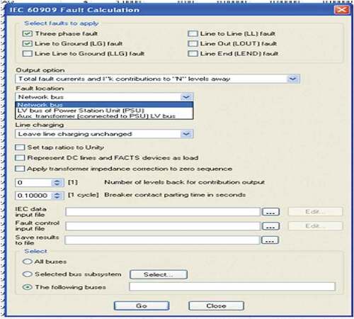
IEC SC current calculation activity in PSS/E version 32 needs additional data for demonstrating machines and transformers. Figure shows main screen of IEC fault calculation in PSS/E with some parameters that can be selected.
Figure 4. IEC fault calculation screen in PSS/E
4. ANSI
In PSS/E, this standard fault current calculation makes use of input data files that have fault locations, maximum operating voltages, and contact parting times; besides ignoring fault resistance.
This standard studies the original network twice: one using equivalent Thevenin resistance only and the other uses equivalent Thevenin reactance only to determine X/R at fault point which is useful for asymmetrical fault current calculation. This is achieved for subtransient and steady state SC current (IEEE, Citation2006; Lakshmi Sankar & Mohamed Iqbal, Citation2015). Correction factors of rotary machines’ impedance have significant effect on SC calculation.
SC current is calculated using two methods (Das, Citation2012):
With prefault voltage V behind the transient reactance which is equal to the terminal voltage at no load; the calculated value of V/X is compared with symmetrical interrupting capability of the protective devices, as long as the circuit X/R ratio equal 17 or less, for three-phase faults. In this case, it is impossible that asymmetrical SC duty exceeds the symmetrical SC duty because the asymmetrical rating of the circuit protective devices exceeds the symmetrical capability.
SC current’ dc component may increase SC duty to the extent that exceeds protective devices rating. These devices might be instantly applied without calculating resistance, X/R ratio, and fault location (remote or local) of the system as long as V/X value doesn’t exceed 80% of symmetrical interrupting capability of the protective switch.
When V/X is found and X/R ratio is known, then protective devices interrupting duty could be estimated by means of multiplying the resultant SC current by a suitable multiplying factor. The multiplying factor depends on: X/R ratio, protective devices contact parting time and decaying effects of ac and dc (Das, Citation2012).
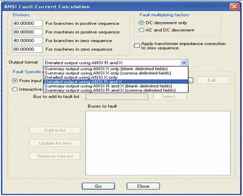
ANSI calculation of SC current activity in PSS/E needs the data of maximum operating voltages, fault positions, and contact parting times. ANSI main screen for fault calculation in PSS/E with some parameters that may be selected is shown in Figure .
Figure 5. ANSI fault calculation screen in PSS/E
5. Automatic sequence calculation (ASCC) (PSS/E, Citation2015)
ASCC offers automatic standard events coverage at all buses contained in a section of the system. Only three-phase and line—to-ground SC can be handled by ASCC. Line-connected shunt devices and charging capacitance can be included in the system model. Apparent impedance at each branch is calculated as follows:
Where iseq, iphase represent current flowing through branch that include line-charging current and current of line-connected devices.
The reciprocal of apparent impedances represents apparent admittances.
ASCC uses existent full working case detail, and generator internal sources’ setup is handled automatically to harmonize conditions just before disturbance application. Mutual and phase self-impedances of each branch are assumed to be balanced when ASCC is applied.
If FLAT option of ASCC is chosen; then data of working case is ignored, all bus voltages are set to (1 + j0), all generator outputs; (PGEN + jQGEN); are set to zero and all phase-shift angles of transformer is to be zero. Beside setting all loads to zero, load current before and after event solution, is ignored.
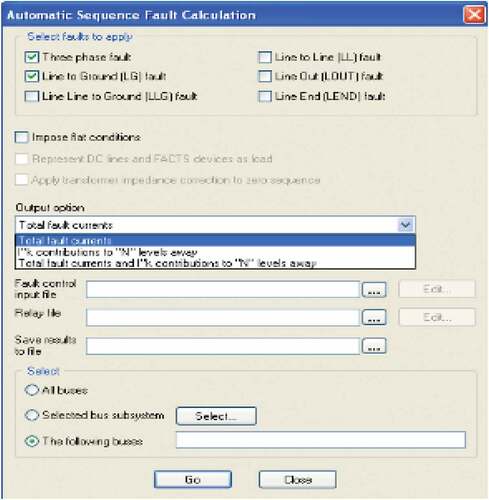
Data need is specified according to various fault and report options in SC calculation activities in ASCC. Figure illustrates main screen of ASCC fault calculation in PSS/E.
Figure 6. ASCC fault calculation screen in PSS/E
6. Comparing ASCC with standards in PSS/E
Each method implements SC studies with PSS/E version 32; ASCC, IEC, and ANSI; requires specific input information, which may differ from one method to another beside those which may met in.
The input information that they met in some methods are shown in Table , and input information dissimilarities are shown in Table . Each method owing its output information is presented in Table .
Table 2. Input information that are common in some methods of fault calculation in PSS/E
Table 3. Input information dissimilarities in fault calculation methods in PSS/E
Table 4. Output information dissimilarities in fault calculation methods in PSS/E
7. Case study
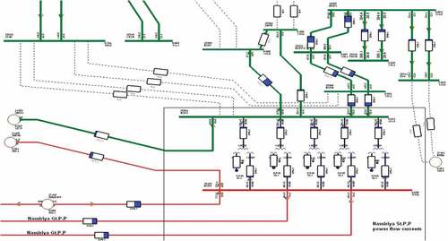
Nassiriya power station is taken as the case study of this paper which have busbar number (25,403) of 400KV that is connected to Nassiriya (4 × 210 MW) power plant and (1 × 40 MW) on 132KV side is connected to busbar number (25,304). SC response has been studied for (L- G) fault and (3PH) fault on busbars (25,403) and (25,304). ANSI C37.5, IEC 60909 standards and ASCC are used to analyze SC response of the system.
Figure shows pwer flow in Nassiriya power plant interconnected to other buses.
Figure 7. Nassiriya power plant power flow diagram
8. Results
It is obvious from previous sections that ASCC doesn’t deal with DC components thus asymmetrical current is not calculated in this method.
For Nassiriya power plant as part of 400 KV, grid is examined with 3-PH and single L-G fault occurrence. SC current results, X/R ratios and factors associated with standards and ASCC is shown in Table and the results is clarified in Figure , which illustrates that the maximum X/R and factor values was used by ANSI for L-G fault while the maximum asymmetrical current occurs during ANSI appliance in case of 3-PH fault.
Figure 8. X/R and factors of faulted Nassiriya 400 KV in ANSI and IEC
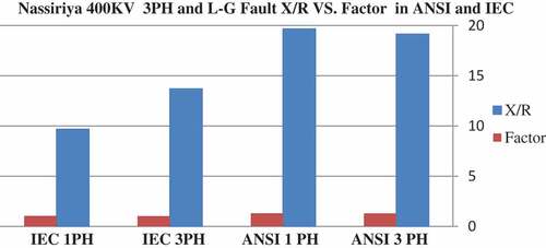
Table 5. SC current, X/R and factors of faulted Nassiriya 400 KV in ANSI, IEC standards & ASCC
For Nassiriya, as part of 132 KV grid, Table shows SC current results, X/R ratios and factors associated with standards and ASCC; corresponding to 3-PH and single L-G fault on Nassiriya 132 KV and results are clarified in Figure which illustrates that the maximum X/R, highest factor, and maximum asymmetrical current occurs during the use of ANSI method.
Figure 9. X/R and factors of faulted Nassiriya 132 KV in ANSI and IEC
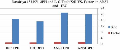
Table 6. SC current, X/R and factors of faulted Nassiriya 132 KV in ANSI, IEC standards and ASCC
The following types of faults are examined on Nassiriya 400 KV and132 KV. SC current and X/R ratio of the connected buses to the faulted bus in ANSI, IEC, and ASCC are shown as below:
Three phase fault in Nassiriya 400 KV: results are listed in Table and cleared in Figure showing that the highest X/R value is within the use of both standards ANSI and IEC at Nassiriya busbar while during the application of ASCC, X/R high value is at Simawa busbar. The ultimate SC current value is also at Nassiriya busbar using IEC standard.
Figure 10. Buses SC current and X/R in ANSI, IEC and ASCC; for three-phase fault on Nassiriya 400 KV
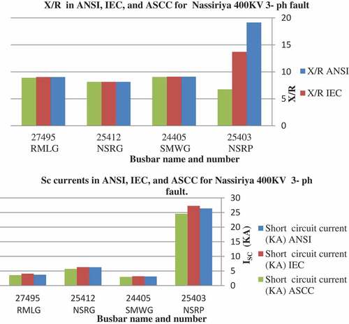
Line to ground fault on Nassiriya 400 KV: results in Table and clarified in Figure showing that IEC SC current value is the highest at Nassiriya busbar.
Figure 11. Buses SC current in ANSI, IEC and ASCC for L-G
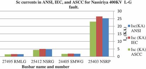
Table 7. SC current and X/R results in ANSI, IEC, and ASCC for 3- PH fault on Nassiriya 400 KV
Table 8. SC current and X/R ratios in ANSI, IEC, and ASCC for L-G fault on Nassiriya 400 KV
8.1. Fault on Nassiriya 400 KV
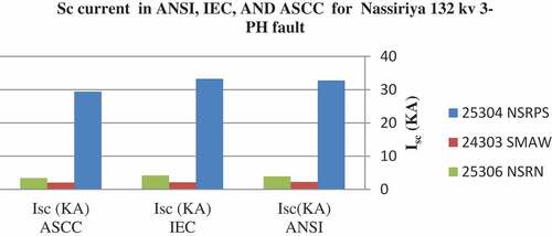
(3) Three phase fault on Nassiriya 132 KV: the ultimate SC current value is by IEC usage as illustrated in Table and Figure .
Figure 12. Buses SC current in ANSI, IEC and ASCC for Nassiriya 132 KV three-phase fault
(4) Line to ground fault on Nassiriya 132 KV: also results ensure that IEC is the highest SC value at Nassiriya busbar as shown in Table and Figure .
Figure 13. Buses SC current in ANSI, IEC, and ASCC for Nassiriya 132 KV L-G fault
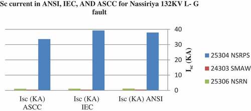
Table 9. SC current and X/R ratios in ANSI, IEC, and ASCC for three phase fault on Nassiriya 132 KV
Table 10. SC current and X/R results in ANSI, IEC, and ASCC for L-G fault on Nassiriya 132 KV
As pointed out in the introduction that there are several programs which calculate the SC by both the ANSI and IEC standards. Lakshmi Sankar and Mohamed Iqbal (Citation2015) reviewed the study of these standards by ETAP for thermal power station by testing the system at different locations such as bus network and bus generator.
It is important to compare Sankar and Iqbal results with the obtained PSS/E results for symmetrical and asymmetrical Fault; Single line to ground and for both the IEC and ANSI standards.
Table shows the SC results of the IEC and ANSI standards by PSS/E for the same system and their results by ETAP in Lakshmi Sankar and Mohamed Iqbal (Citation2015). Comparison results represent a convergent benchmark.
Table 11. Results of the IEC and ANSI standards by PSS/E and ETAP results for symmetrical and unsymmetrical Fault
9. Conclusion
Paper results are obtained by using ANSI, IEC 60909 standards and ASCC using PSS/E version 32. Standards give methods to calculate symmetrical steady state current that is multiplied by a factor for the purpose of finding the peak value of asymmetrical current; ANSI output gives the value of that factor while it was a hand calculation in IEC in Tables and . Giving that ASCC doesn’t deal with dc current; thus asymmetrical current is not calculated in that method and also the factor. In L-G fault, X/R of Nassiriya 400 KV and 132 KV buses is not given by IEC method and was a hand calculation in Tables and 1, respectively.
ANSI adjusts machine reactance using a multiplier; these multipliers don’t take into account fault position and break parting time, while IEC recommends including parting time and making machine proximity to SC.
However, ASCC and ANSI are accepted methods for SC calculation. But when studies for the grid expansion are held, it is important to use IEC fault current calculation for its high accuracy resulting in a protected grid, as the instantaneous SC current are used for determining breaking capacity.
Additional information
Funding
Notes on contributors
Yasar N. Lafta
Yasar N. Lafta received the B.S. degree/University of Technology in 1990, MSc degree of Electrical engineering/the college of Electrical & Electronic Techniques (Baghdad) in 2011. She experienced 10 years work as researcher/Mechatronics department/University of Baghdad. Her current article focuses on comparative study between 3 methods of short circuit current calculation and recommended IEC standard to be applied to the Iraqi grid in case of modeling planned expansion.
Nadheer A. Shalash
Nadheer A. Shalash received the B.S. degree in 2003, the M.S. degree in 2008, and the PhD degree in Electrical Power engineering/University Malaysia Pahang in 2015.
He worked as lecturer since 2009/Al- Mamoon University Collage/Baghdad.
Yaser N. Abd
Yaser Nadhum Abd earned his MSc in electrical engineering/university of Baghdad in 1999. His current position is head of Electrical Studies Department in the Ministry of Electricity.
Ali A. Al- Lami
Ali Adel AL-Lami earned his BSc in electrical engineering/university of technology in 2006. His current position is assistant chief engineer in the Ministry of Electricity.
References
- Ahmedi, S., & Azhari, S. J. (2018, April). A novel fully differential second generation current conveyor and its application as a very high CMRR instrumentation amplifier. Emerging Science Journal, 2(2). doi:10.28991/esj-2018-01131
- Berizzi, A., Massucco, S., Silvestri, A., & Zaninelli, D. (1994, July/August). Short -circui t current a comparison between methods of IEC and ANSI standards using dynamic simulation as reference. IEEE Transactions on Industry Applications, 30(4), 1083–17. doi:10.1109/28.297926
- Choi, N., Park, B., Cho, H., & Lee, B. (2019). Impact of momentary cessation voltage level in inverter-based resources on increasing the short circuit current. Sustainability, 11(4), 1153. doi:10.3390/su11041153
- Das, J. C. (2012). Power system analysis, short circuit load flow and harmonics. USA: CRC press- Taylor and Francis group.
- Sweeting, D. (2012, March/April). Applying IEC 60909, fault current calculations, IEEE Transactions on Industry Applications, 48(2), 575–580. doi:10.1109/TIA.2011.2180011
- de Metz-noblat, B., Dumas, F., & Poulain., C. (2005). Calculation of short-circuit current. Schneider Electric’s, Cahier Technique, 158, 1–32.
- Ding, Z., Ge, J., Cao, W., Qi, X., & Yang, W. (2011). A comparison of short-circuit current decaying calculation between PSS/E BKDY and computational curve. Advanced Material Research, 354–355, 1126–1131.
- Gallucci, R. H. V. (2018). Risk-deformed regulation: What went wrong with NFPA 805,”. Civil Engineering Journal, 4(12). doi:10.28991/cej-03091205
- Habbi, H. M., & Alhamadani, A. (2018, May). Power system stabilizer PSS4B model for Iraqi national grid using PSS/E Software. Journal of Engineering, 24(5), 29–45. doi:10.31026/j.eng.2018.05.03,
- IEEE. (2006). IEEE recommended practice for calculating short - circuit current in industrial and commercial power systems. New York, NY: Institute of Electrical and Electronics Engineers, Inc.
- International Standard IEC. (2016, January). International standard IEC 60909-0, short-circuit current in three-phase AC Systems- part 0: Calculation of current (edition 2.0 ed.), International Electrotechnical Commission, Geneva, Switzerland.
- Jahanirad, H., & Karam, H. (2017, December). BIST-based testing and diagnosis of LUTs in SRAM-based FPGAs. Emerging Science Journal, 1(4). doi:10.28991/ijse-01125
- Kaloudas, C. G., Papadopoulos, P. N., Papadopoulos, T. A., Marinopoulos, A. G., & Papagiannis., G. K. Short-circuit analysis of an isolated generator and comparative study of IEC, ANSI and dynamic simulation,” 7th Mediterranean Conference and Exhibition on Power Generation, Transmission, Distribution and Energy Conversion Agia Napa, Cyprus, Stevenage, Hertfordshire, 7–10 November 2010, doi: 10.1049/cp.2010.0922.
- Lafta, Y. N., Shalash, N. A., Abd, Y. N., & Al- Lami., A. A. (2018). Power flow control of Iraqi international super grid with two terminal HVDC techniques using PSS/E. International Journal of Control and Automation, 11(5), 201–212. doi:10.14257/ijca.2018.11.5.18
- Lakshmi Sankar., S., & Mohamed Iqbal., M. (2015, July). ANSI and IEC Standards based short circuit analysis of a typical 2 × 30 MW thermal power plant. Middle East Journal of Scientific Research, 23(8), 1617–1625. doi:10.5829/idosi.mejsr.2015.23.08.22406
- Najafi, M., Ebrahimi, R., Babaee, A., & Hoseynpoor, M. (2011). Fault analysis in unbalanced and unsymmetrical distribution systems. Australian Journal of Basic and Applied Sciences, 5(8), 743–756.
- Nedic, D., Bathurst, G., & Heath, J. A comparison of circuit calculation methods and guidelines for distribution networks. 19th International Conference on Electricity Distribution, Vienna, 21–24 May 2007.
- PSS/E. (2015, March). PSS/E 34.0. Program application guid. (Vol. I). Schenectady, NY, USA: Siemens P.T.I.
- Rodolakis., A. J. (1993, May/June). A Comparison of North American (ANSI) and European (IEC) Fault Calculation Guideline. IEEE Transactions on Industry Applications, 29(3). doi:10.1109/28.222420
- Schlabbach, J. (2008). Short-circuit Current. London: IET power and energy series 51, Institution of Engineering and Technology.
- Thurner, L., & Braun, M. Vectorized calculation of short circuit current considering distributed generation - an open source implementation of IEC 60909,” IEEE PES Innovative Smart Grid Technologies Conference Europe (ISGT-Europe), Sarajevo, Bosnia-Herzegovina, 5 Feb 2018, doi: 10.1109/ISGTEurope.2018.8571529.
- Yousefikia, M., Gharibreza, E., & Baledi, M. (2015). Improvement DFIG Behaviour against Symmetrical Short Circuit Fault by Superconducting Current Limiter,”. European Journal of Advances in Engineering and Technology, 2(9), 1–7.