
 ?Mathematical formulae have been encoded as MathML and are displayed in this HTML version using MathJax in order to improve their display. Uncheck the box to turn MathJax off. This feature requires Javascript. Click on a formula to zoom.
Abstract
A continuous electrolysis system using an electrolysis reactor cell separated into an anode cell and a cathode cell by a perforated plate as a diaphragm was operated in a laboratory to remove fluoride (F-) from hot spring wastewater to meet the Japanese national minimum effluent standard for F- of 8 mg/L. The perforated plate was 5 mm thick and had 740 holes with a diameter of 1.2 mmφ. F- was removed by co-precipitation with magnesium hydroxide (Mg(OH)2) produced in the cathode cell. Water from Gero Hot Spring containing 17.0 mg/L of F- was used as a model wastewater. Since Gero Hot Spring water does not contain magnesium (Mg2+), magnesium carbonate (MgCO3) was added as a form of slurry into the anode cell with the hot spring water. The hot spring water containing Mg2+ passed through the perforated plate and flowed into the cathode cell, where Mg(OH)2 was co-precipitated with F- due to hydroxide ion (OH-) produced by electrolysis. Alkalinity (Alk), which interferes with the precipitation of Mg(OH)2 by forming MgCO3 in the cathode cell, was removed in the anode cell by hydrogen ion (H+) produced by electrolysis. Various combinations of the added Mg2+ concentration (Mgi) and the applied current (Ia) were tested to elucidate the effect of these parameters on F- removal (ΔF). It was revealed that, less than 8 mg/L of the F- concentration in treated water (F (treated)), which is the Japanese national minimum standard for wastewater, was achieved when the Mgi was between 85 and 110 mg/L and Ia was more than 90 mA.
PUBLIC INTEREST STATEMENT
Many hot springs in Japan contain high concentrations of fluoride. In consideration of impact on the environment, the Japanese Ministry of the Environment has set the minimum effluent standards for fluoride and arsenic in wastewater at 8 mg/L and 100 µg/L, respectively. Thus far, however, no suitable treatment technologies are available from the viewpoint of removal efficiency and cost. This paper presents clues on the development of a novel treatment system to remove fluoride and arsenic from wastewater from hot spring facilities. It is possible to apply this technique not only to hot spring wastewater but to industrial wastewater containing fluoride and arsenic.
1. Introduction
Hot springs are popular Japanese tourist attractions, and numerous resort towns are centered on hot springs. Dissolved matter in hot springs is believed to provide health benefits when people soak in a hot spring. However, hot springs sometimes contain materials not good for the environment, such as fluoride (F−). In 2001, the Japanese Ministry of Environment set the national minimum effluent standard for fluoride at 8 mg/L. (Ministry of the Environment Government of Japan, Citation2018) However, a provisional standard was applied to hotels with hot springs since no appropriate treatment techniques were available. (Ministry of the Environment Government of Japan, Citation2016) The provisional standard has a period of three years; however, even by 2016, no effective technology had been found even though the Japanese Ministry of Environment had invited private companies to compete to develop treatment techniques for wastewater. Accordingly, the provisional standard of 15–50 mg/L is still applied to hotels with hot springs. (Ministry of the Environment Government of Japan, Citation2018, Citation2016)
To remove F− for industrial wastewater treatment, calcium ions are often added to produce insoluble precipitation of calcium fluoride; however, obtaining 8 mg/L of F− requires the addition of much more calcium than that calculated from stoichiometry. (Saha, Citation1993) A high amount of the source of calcium as well as the produced sludge causes cost rising, which cannot be afforded by the hot water spring industries. In addition to chemical precipitation, adsorption, ion exchange, and reverse osmosis (RO), electrodialysis and electrocoagulation techniques can be used for removing F− from water. (Maurice, Citation2006) However, co-existing contaminants in hot springs degrade the effectiveness of adsorption and ion exchange. (Amit, Kumar, & Sillanpää, Citation2011; Paripurnanda, Vigneswaran, Kandasamy, & Naidu, Citation2013) Bone char is a well-known adsorbent that selectively adsorbs F−; however, its low adsorption capacity (5 mg/g) means that a large amount of bone char is needed. (Fawell et al., Citation2006; Herath, Sunali, Tomonori, & Masamoto, Citation2018; Medellin-Castillo et al., Citation2014; Rojas-Mayorga et al., Citation2013) When we consider treatment of Gero Hot Spring, one of the most famous hot springs in Japan and the focus of this paper, the volume of hot spring water is 3300 m3/day with a F− concentration of 16.5 mg/L. (xxxx, Citation0000) This means that, 5600 kg/day of bone char is required to achieve the F− concentration of 8 mg/L, and it is not realistic to prepare this amount of bone char every day. Kato et al. proposed to use a waste gypsum apatite to remove F− and showed 9.1 mg/g of adsorption capacity, (Katoh, Hada, Kitagawa, Terao, & Sato, Citation2014) which would require 3100 kg/day of waste gypsum apatite. This is not realistic because it requires too much apatite and produces too much sludge.
RO and electrodialysis are available for fluoride removal of drinking water. However, in wastewater treatment, the rejected water from RO and electrodialysis containing high concentrations of fluoride should be treated by an additional method, since the entire volume of water should be treated. (Sachin et al., Citation2015) In the electrocoagulation system, sacrificial electrodes, usually aluminum plates, are used for anodes. The aluminum eluted by electrolysis forms a complex with F− and precipitates. (Mameri et al., Citation1998),Guzmán, Nava, Coreño, Rodríguez, & Gutiérrez, Citation2016) The cost of the sacrificial electrodes and of the treatment of the sludge are not affordable.
The technology to remove F− from a solution by an electrolysis system has been developed by the authors. (Tomonori et al., Citation2018; Yuki, Konishi, & Kawakami, Citation2019; Yuki, Yanagawa, Konishi, & Kawakami, Citation2017) The electrolysis system is a method in which a solution containing magnesium (Mg2+) is electrolyzed in an electrolysis cell separated by a diaphragm into an anode cell and a cathode cell. When the electrolysis is performed, the following reactions take place in the cathode (EquationEquation (1)(1)
(1) ) and in the anode (EquationEquation (2)
(2)
(2) ) to produce hydroxide ion (OH−) and hydrogen ion (H+), respectively.
As the pH increases in the cathode cell due to OH− produced by EquationEquation (1)(1)
(1) when the electrolysis is performed, Mg2+ contained in the solution precipitates as magnesium hydroxide (Mg(OH)2); at that time, F− is co-precipitated with Mg(OH)2 to be removed. (Tomonori et al., Citation2018)
In the electrolysis system, alkalinity (carbonate and bicarbonate) must be removed in advance, since it suppresses the production of Mg (OH)2 by forming magnesium carbonate (MgCO3). (Yuki et al., Citation2017) Well water (drinking water) containing Mg2+ and F− was treated by a batch-type electrolysis system, using a membrane filter for the diaphragm, and it was shown that, the electrolysis system effectively removed F−. (Tomonori et al., Citation2018) When the treatment system is applied to drinking water, it is enough to treat part of the water volume; on the contrary, when it comes to hot spring wastewater, the entire volume should be treated. Therefore, electrolysis treatment by a continuous flow reactor with a diaphragm made of an unglazed plate, which is more durable and cheaper than a membrane filter, was performed. (Yuki et al., Citation2019) It was confirmed that, the system achieved a concentration of less than 8 mg/L of F−. However, in a long-term operation, plugging of the unglazed plate caused a gradual increase in power consumption due to increased electrical resistance, requiring increased voltage. Therefore, in this study, as a novel system for removing F−, an electrolysis system using a perforated plate as a diaphragm was tested, and its performance was evaluated.
2. Material and methods
2.1. The principle of the perforated plate
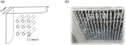
The perforated plate used for a diaphragm of the electrolysis system in the current study was a plastic plate 5 mm thick having holes with a diameter of 1.2 mmφ with 3 mm interstices. Figure show a schematic diagram and a photo of the perforated plate, respectively. Small holes with a diameter of 1.2 mmφ suppress eddy diffusion, which bears most of the mass transfer in water. Since the molecule diffusion transports much less mass transfer in water, (Marion, Citation2008) the solutions separated by the perforated plate do not mix easily. On the other hand, this perforated plate can be used as a diaphragm, since electrons and ions can pass through holes when there is a potential gradient.
Figure 1. (a) Schematic diagram of the perforated plate (b) Photo of the perforated plate
2.2. Outline of experimental equipment
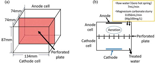
The water of Gero Hot Spring in Japan’s Gifu Prefecture was used as a model wastewater. Table shows the water quality of Gero Hot Spring from literature (Gifu Research Center for Public Health, Citation2013) and as measured. The literature value and the measured value coincided well with each other; the F− concentrations were 16.5 mg/L and 17.0 mg/L, respectively. Figure ,b) show an overview of the electrolysis reactor when a perforated plate was used for the diaphragm. Figure ) is a schematic diagram of the electrolytic cell, which had dimensions of 134 mm (W) * 74 mm (D) * 87 mm (H) for each cell. The perforated plate had dimensions of 134 mm (W) * 87 mm (H) and had 740 holes. Figure ) is a top view of the electrolysis cells. The raw water (Gero Hot Spring water) was allowed to flow into the anode cell at 7 mL/min, which was equivalent to 10 L/day. The retention time in each cell was 100 minutes. Since Gero’s hot spring water does not contain Mg2+, as is shown in Table , MgCO3 was added to the anode cell as a form of slurry with a concentration of 50 g/L. The magnesium concentration to be added was adjusted by changing the flow rate of the MgCO3 slurry. For example, to obtain a magnesium concentration of 100 mg/L, the flow rate of the MgCO3 slurry was set to 0.056 mL/min.
Table 1. Water quality of Gero Hot Spring
The electrode used a platinum-coated titanium plate for the anode and a stainless steel wire for the cathode. In the anode cell, H+ produced according to EquationEquation (2)(2)
(2) reacts with MgCO3 to produce carbon dioxide (CO2). Consequently, alkalinity is removed, and Mg2+ dissolves into the solution (EquationEquation (3)
(3)
(3) ).
Aeration was performed in the anode cell to remove CO2 from the solution. The raw water from which alkalinity was removed in the anode cell passes through the holes in the perforated plate to the cathode cell. In the cathode cell, the pH rises by the OH− produced by EquationEquation (1)(1)
(1) to precipitate Mg(OH)2, which co-precipitates F−.
The electrolysis was performed under a constant current. A constant current power supply (TAKASAGO ZX-S-400M) was used for a DC power supply.
Figure 2. (a) Electrolysis reactor (b) Top view of the reactor
2.3. Experimental conditions
In this study, the effect of the Mg2+ concentration and the applied current on F− removal was investigated. An increase in the concentration of Mg2+ could increase the amount of Mg(OH)2 precipitation in the cathode, leading to increased co-precipitation with F−. An increase in the applied current could increase the amount of Mg(OH)2 precipitation in the cathode cell when adequate Mg2+ is available. In addition, it could reduce the excessive alkalinity in the cathode cell, according to EquationEquation (3)(3)
(3) . On the contrary, too much current could cause excessive H+, which suppress the increase of pH in the cathode cell after all alkalinity is consumed in the anode cell. Therefore, the combination of Mg2+ and the applied current (Ia) is an important factor of the system. When the Mg2+ concentration was 50 mg/L, Ia varied as 50, 80, and 100 mA. When the Mg2+ concentration was 100 mg/L, Ia varied as 80, 100, and 120 mA. When the Mg2+ concentration was 150 mg/L, Ia varied as 80, 100, 120, and 150 mA. A total of 10 experiments were conducted. In the current electrolysis system, Ia of 50, 80, 100, 120, and 150 mA were equivalent to charge loadings of 430, 690, 860, 1040, and 1300 Coulomb/L, respectively.
2.4. Analyses
When the system was stabilized after more than 20 hours of operation, the water in the anode cell and the treated water were sampled. These samples were filtered for analysis through a membrane filter with a pore size of 0.45 µm (Cobetter Lab, Unichro Syringe Filter, Type PES).
The ion concentrations of F−, chloride ion (Cl−), nitrate ion (NO3−), sulfide ion (SO42-), sodium ion (Na+), potassium ion (K+), ammonium ion (NH4+), Mg2+, and calcium ion (Ca2+) were analyzed using an ion chromatograph (Cation: Thermo ICS1500, Separation column IonPac CS12A, Eluent Methanesulfonic acid 30 mmol/L, Suppressor CERS 500), (Anion: Thermo ICS2000, Separation column IonPac AS18, Eluent KOH 23–40 mmol/L (gradient), Suppressor AERS 500).
The pH was measured with a BECKMAN ∅32 pH Meter (electrode: BECKMAN 511,070). The alkalinity was determined by taking the difference between the total cation charge and total anion charge obtained by the ion chromatograph and the pH measurement.
2.5. Model calculation
An empirical model was established to estimate the F− concentration in the treated water F (treated) using the experimental results with various combinations of the initial Mg2+ concentration (Mgi) and Ia in the operation of the electrolysis system. As mentioned previously, F− removal (ΔF) is affected by the alkalinity in the anode cell (Alk) and the concentration of Mg precipitated (ΔMg), since F− is removed by co-precipitation with Mg(OH)2. Therefore, Alk and ΔMg were the important parameters for estimating ΔF.
The empirical model established first predicts Alk and ΔMg from Ia and Mgi, and then it predicts ΔF from the predicted Alk and ΔMg.
Alk was estimated by a polynomial equation, as shown in EquationEquation (4)(4)
(4) , where a and b are the model constants. The values of a and b were varied to obtain the best fit of the estimated value to the measured value. After obtaining the model constants of a and b, a correction was made to Alk when Alk was 0 or less by EquationEquation (4)
(4)
(4) . In such a case, Alk was regarded as 0, as shown in EquationEquation (5)
(5)
(5) , since even when Alk had a negative value, the carbonate in the solution that affects the precipitation of Mg(OH)2 was regarded as 0.
where Mgi is the initial concentration of Mg (mg/L),
Ia is the applied current (mA), and
Alk is the alkalinity in the anode cell (µeq/L).
The Mg concentration in the treated water (Mg (treated)) was estimated by a polynomial equation, as shown in EquationEquation (6)(6)
(6) . In the equation, a’ and b’ are the model constants. The values of a’ and b’ were varied to obtain best fit of the estimated value to the measured value. ΔMg was calculated by EquationEquation (7)
(7)
(7) . Since it is reported that F− is not co-precipitated with Mg(OH)2 when the concentration of magnesium ions is less than 20 mg/L, (Yuki & Kawakami, Citation2019) ΔMg should not be taken into account when the Mg (treated) is less than 20 mg/L. EquationEquation (8)
(8)
(8) shows the correction when the Mg (treated) was less than 20 mg/L.
where ΔMg is the concentration of Mg precipitated (mg/L), and
Mg (treated) is the Mg concentration in the treated water (mg/L).
As the next step, ΔF was estimated by EquationEquation (9)(9)
(9) , where a” and b” are the model constants. The values of a” and b” were varied to obtain best fit of the estimated value to the measured value. F (treated) was calculated by EquationEquation (10)
(10)
(10) .
where F (treated) is the F− concentration in the treated water (mg/L), and
F (raw water) is the F− concentration in the raw water, here 17.0 mg/L.
3. Results and discussion
3.1. Electrolysis system with a perforated plate as a diaphragm
Figures and show the relationship between Ia and F (treated) and the relationship between Ia and Alk, respectively, in different Mgi. When compared at the same Mgi, smaller Ia, higher F (treated), and higher Alk were observed. With the small Ia in the high Mgi, Alk was not sufficiently removed, leading to less ΔF. The relationship between Alk and F (treated) is shown in Figure . It clearly shows that when Ia was small, the alkalinity remaining in the anode cell hindered ΔF by producing MgCO3 in the cathode cell, which interfered with the precipitation of Mg (OH)2. However, when comparing F (treated) in the different Mgis, lower F (treated) can be seen when Mgi was higher at the same Alk. For example, according to Figure , F (treated) were 3.8 mg/L, 7.7 mg/L, and 13.3 mg/L for 150 mg/L, 100 mg/L, and 50 mg/L of Mgi, respectively, at Alk of 1500 µeq/L. According to Figure , Ias that gave Alk of 1500 μeq/L were 50 mA, 90 mA, and 150 mA for Mgis of 50 mg/L, 100 mg/L, and 150 mg/L, respectively. Figure shows the relationship between Ia and ΔMg. When Ias that gave Alk of 1500 μeq/L are applied to Figure , ΔMgs of 36 mg/L, 90 mg/L, and 148 mg/L were obtained for Mgis of 50 mg/L, 100 mg/L, and 150 mg/L, respectively. Therefore, higher ΔF was achieved by the higher ΔMg when Mgi was higher at the same Alk.
Figure 3. Relationship between Ia and F (treated)
Figure 4. Relationship between Ia and Alk
Figure 5. Relationship between Alk and F (treated)
Figure 6. Relationship between Ia and ΔMg
3.2. Model calculation
From Mgi and Ia, Alk was estimated by a regression analysis as EquationEquation (11)(11)
(11) , based on EquationEquation (4)
(4)
(4) .
The positive coefficient for Mgi is caused by the alkalinity from the added MgCO3. The negative coefficient for Ia is caused by the reduction of alkalinity by H+ produced by EquationEquation (2)(2)
(2) .
Figure shows a good relationship between the measured Alk with the estimated Alk in the anode cell by EquationEquations (11)(11)
(11) and (Equation5
(5)
(5) ).
From Mgi and Ia, Mg (treated) was estimated by a regression analysis, as shown in EquationEquation (12)(12)
(12) , based on EquationEquation (6)
(6)
(6) .
The positive coefficient for Mgi indicates that more Mg2+ remained in the cathode solution when more MgCO3 was added to the anode cell, and the negative coefficient for Ia indicates that more current produced more precipitation of Mg.
Figure shows a comparison of the measured ΔMg and estimated ΔMg by EquationEquations (12)(12)
(12) , (Equation7
(7)
(7) ), and (Equation8
(8)
(8) ). The estimated ΔMg had a good correlation with the measured ΔMg.
It was revealed that Alk and ΔMg could be estimated from Mgi and Ia. As a next step for estimating ΔF, a regression analysis was done by using the estimated values of Alk by EquationEquations (11)(11)
(11) and (Equation5
(5)
(5) ) and ΔMg by EquationEquations (12)
(12)
(12) , (Equation7
(7)
(7) ), and (Equation8
(8)
(8) ). From the estimated Alk and ΔMg, ΔF− was estimated by a regression analysis, as shown in EquationEquation (13)
(13)
(13) , based on EquationEquation (9)
(9)
(9) .
The negative coefficient for Alk reflects alkalinity’s interference with F− removal, and the positive coefficient for ΔMg reflects F− removal by co-precipitation with Mg(OH)2.
Figure shows the measured F (treated) and estimated F (treated) according to EquationEquations (13)(13)
(13) and (Equation10
(10)
(10) ). F (treated) was successfully estimated by the model.
By applying this model, the combinations of Mgi and Ia were calculated so that, the effluent standard of 8 mg/L of F (treated) was achieved. The results are shown in Figure . When the Ia was more than the combination in Figure , less than 8 mg/L of F (treated) would be achieved. However, when the Mgi was less than 83 mg/L, F (treated) less than 8 mg/L was not achieved, even when a high current was applied. This is because the ΔMg was not sufficient to decrease F− by co-precipitation. According to Figure , more than 110 mg/L of Mgi caused an increase in the current, indicating that, the best combination of Mgi and Ia rises between 83 mg/L and 110 mg/L of Mgi. Appropriate Ia should be chosen by a cost comparison of MgCO3 and electricity.
The production of sludge can be estimated by assuming 110 mg/L as Mgi and 9 mg/L as ΔMg to meet the minimum standard for F− of 8 mg/L, since the hot spring water of Gero contained 17.0 mg/L of F−. According to the model, 19 mg/L of magnesium remained in the treated water, indicating 91 mg/L of magnesium, which is equivalent to 220 mg/L of Mg(OH)2 precipitates. When 3300 m3/day is taken into consideration as the volume of the wastewater, the amount of sludge would be 730 kg/day, which is much less than that produced by adsorption systems.
Figure 7. Measured Alk and estimated Alk
Figure 8. Measured ΔMg and estimated ΔMg
Figure 9. Measured F (treated) and estimated F (treated)
Figure 10. Combinations of Mgi and Ia that produce 8 mg/L of F (treated)
4. Conclusions
A continuous electrolysis system using an electrolysis reactor cell separated into an anode cell and a cathode cell by a perforated plate as a diaphragm was operated to remove F− from hot spring wastewater to meet the national minimum effluent standard for fluoride, set at 8 mg/L. Water from Gero Hot Spring, which contained 17.0 mg/L of F− concentration, was used as a model wastewater. Since water from Gero Hot Spring does not contain magnesium, MgCO3 was added to the hot spring water as a Mg2+ source.
The electrolysis system was operated with various combinations of Mgi and Ia to elucidate the effect of these parameters on ΔF. ΔF was affected negatively by Alk in the anode cell and positively by the precipitated Mg2+ (ΔMg) in the cathode cell. Alk interfered with the precipitation of Mg(OH)2 when Ia was not enough to remove Alk. Based on the experimental results, F (treated) was estimated from Mgi and Ia by an empirical model. The model could well reproduce measured F (treated). The model indicated that less than 8 mg/L of F (treated), which is the Japanese national minimum standard for wastewater, would be achieved when the Mgi was between 85–110 mg/L, and more than 90 mA of Ia was applied.
Additional information
Funding
Notes on contributors
Tomonori Kawakami
Yuki Imai is a student of the Graduate School of Engineering at Toyama Prefectural University, Japan. The focus of her research is to develop a technology to remove fluoride and arsenic from wastewater to levels below the minimum effluent standard. She has experimented with removing fluoride and arsenic by co-precipitation with magnesium hydroxide. Magnesium hydroxide is produced in a cathode cell of an electrolysis system. Her novel idea is to apply a perforated plate as a diaphragm that separates the cathode cell from the anode cell. The advantages of the perforated plate are described in the manuscript.
References
- Amit, B., Kumar, E., & Sillanpää, M. (2011). Fluoride removal from water by adsorption - A review. Chemical Engineering Journal, 171(3), 811–11.
- Fawell, J., Bailey, K., Chilton, J., Dahi, E., Fewtrell, L., & Magara, Y. (2006). Fluoride in drinking-water, world health organization. London, UK: IWA publishing.
- Gifu Research Center for Public Health. (2013). Hot spring analysis data, 13B04774, No. 125.
- Guzmán, A., Nava, J. L., Coreño, O., Rodríguez, I., & Gutiérrez, S. (2016). Arsenic and fluoride removal from groundwater by electrocoagulation using a continuous filter-press reactor. Chemosphere, 144, 2113–2120. doi:10.1016/j.chemosphere.2015.10.108
- Herath, H. M., Sunali, A., Tomonori, K., & Masamoto, T. (2018). Regeneration of Exhausted chicken bone char (CBC) to Optimize its usage in the defluoridation of drinking water. Journal of Ecotechnology Research, 18(3), 39–46.
- Katoh, M., Hada, S., Kitagawa, S., Terao, H., & Sato, T. (2014). Removal of fluoride from wastewater of hot spring by hydrixyapatite synthesized from gypsum waste and its optimum treatment. Journal of Japan Society of Civil Engineers, 70(7), III_517-III_525. doi:10.2208/jscejer.70.III_517
- Mameri, N., Yeddou, A. R., Lounici, H., Belhocine, D., Grib, H., & Bariou, B. (1998). Defluoridation of septentrional Sahara water of north Africa by electrocoagulation process using bipolar aluminium electrodes. Water Research, 32(5), 1604–1612. doi:10.1016/S0043-1354(97)00357-6
- Marion, A. (2008). Physical Transport Processes in Ecology. Advection, Diffusion, and Dispersion, Encyclopedia of Ecology, 2739–2744.
- Maurice, S. (2006). Onyango and Hitoki Matsuda, fluoride removal from water using adsorption technique. Fluoride and the Environment, 2, 1–48.
- Medellin-Castillo, N. A., Leyva-Ramos, R., Padilla-Ortega, E., Ocampo Perez, R., Flores-Cano, J. V., & Berber-Mendoza, M. S. (2014). Adsorption capacity of bone char for removing fluoride from water solution. Role of hydroxyapatite content, adsorption mechanism and competing anions. Journal of Industrial and Engineering Chemistry, 20(6), 4014–4021. doi:10.1016/j.jiec.2013.12.105
- Ministry of the Environment Government of Japan. (2016) Notification, No.1606161, Review of the temporal minimum effluent standard for boron, fluoride, ammonium, nitrite and nitrate.
- Ministry of the Environment Government of Japan. (2018). Exploration into development and dissemination of technology for wastewater treatment from hot spring. http://www.env.go.jp/water/onsen-haisui/tech.html
- Paripurnanda, L., Vigneswaran, S., Kandasamy, J., & Naidu, R. (2013). Defluoridation of drinking water using adsorption processes. Journal of Hazardous Materials, 248–249, 1–19.
- Rojas-Mayorga, C. K., Bonilla-Petriciolet, A., Aguayo-Villarreal, I. A., Hernández-Montoy, V., Moreno-Virgen, M. R., Tovar-Gómez, R., & Montes-Morán, M. A. (2013). Optimization of pyrolysis conditions and adsorption properties of bone char for fluoride removal from water. Journal of Analytical and Applied Pyrolysis, 104, 10–18.
- Sachin, V. J., Bringas, E., Yadav, G. D., Rathod, V. K., Ortiz, I., & Marathe, K. V. (2015). Arsenic and fluoride contaminated groundwaters: A review of current technologies for contaminants removal. Journal of Environmental Management, 162, 306–325. doi:10.1016/j.jenvman.2015.07.020
- Saha, S. (1993). Treatment of aqueous effluent for fluoride removal. Water Research, 27(8), 1347–1350.
- Tomonori, K., Nishino, M., Imai, Y., Miyazaki, H., Amarasooriya, A. A. G. D., & Amosa, M. K. (2018). De-fluoridation of drinking water by co-precipitation with magnesium hydroxide in electrolysis. Cogent Engineering, 5(1). doi:10.1080/23311916.2018.1558498
- xxxx (0000). https://www.hankyu-travel.com/onsen/gero/hotspring.php
- Yuki, I., & Kawakami, T. (2019). Fluoride removal from hot spring waste water by an electrolysis method and its mechanoism. Journal of Japan Society of Civil Engineers, 75(5), I_403-I_410.
- Yuki, I., Konishi, M., & Kawakami, T. (2019). Removing arsenic and fluoride from hot spring water by electrolysis. International Journal of GEOMATE, 17(62), 71–76.
- Yuki, I., Yanagawa, S., Konishi, M., & Kawakami, T. (2017). Removing fluoride from a hot spring using an electrolysis system. International Journal of GEOMATE, 12(32), 101–106.