
 ?Mathematical formulae have been encoded as MathML and are displayed in this HTML version using MathJax in order to improve their display. Uncheck the box to turn MathJax off. This feature requires Javascript. Click on a formula to zoom.
Abstract
The influence of rail pressure control on fuel consumption, emissions and combustion in an automotive downsized turbocharged diesel engine was investigated, considering different operating modes in three-part load working conditions. These modes were selected according to the results of a previous step of the study, where low NOX and fuel consumption levels were obtained managing a hybrid exhaust gas recirculation (EGR) system and the turbocharger variable nozzle turbine (VNT). Aiming at limiting observed soot penalties, increased values of rail pressure were applied, deepening the interactions with engine-controlled sub-assemblies and the related variations in operating, environmental, energy and combustion parameters. At low levels of engine speed and load, major reduction in NOX emissions and fuel consumption were observed, with acceptable soot and noise combustion increase, while turbocharger speed was also enhanced. No variations in fuel consumption were achieved at higher load and speed, while soot penalty remained significant. A simplified method to describe and model engine behaviour and combustion process was also developed, defining linear relationships between rail pressure and engine quantities, including a wide set of combustion parameters derived from in-cylinder pressure diagrams and heat release curves.
PUBLIC INTEREST STATEMENT
Despite the reduction of their popularity, diesel engines are still a widespread solution for road vehicles and transportation sector. Methods to reduce their environmental impact and greenhouse gases emissions are therefore required, as well as tools to deepen their behaviour. This investigation was therefore focused on the possibility to reduce emissions and fuel consumption through the integrated control of the main systems fitted on an automotive engine. Extended experimental tests were therefore made to compare different strategies considering operating conditions related to the engine use in common vehicle driving mode. A significant reduction of NOX emissions was achieved, while decreasing fuel consumption in most of the selected operating points. Furthermore, knowledge and methods were obtained which will be applied in investigations aiming at the comparison of different alternative fuels, for a further reduction of environmental impact of this type of engines.
1. Introduction
Notwithstanding the strong competition of alternative powertrain systems, internal combustion engines (ICEs) have still a major role to play in the transportation sector for the next years, both in stand-alone or hybrid applications. Under the pressure coming from the worldwide legislation on chemical pollutants and carbon dioxide emissions, further developments are expected covering a wide range of technical aspects.
Major enhancements of advanced combustion modes and after-treatment devices (lean NOX systems, oxidation catalysts and particulate filters) are the most important actions for emissions control. For efficiency gains, combustion, fuel and air handling systems require significant developments (Johnson & Joshi, Citation2018).
Proper operation and management of sub-systems such as fuel injection equipment, turbocharger and exhaust gas recirculation (EGR) circuits are as well requested, in order to grant performance, fuel consumption and exhaust boundary conditions. The relevant interactions present interesting issues to be deepened, as the number of control variables is very large, requiring extended experimental and numerical investigations to achieve correct targets.
Considering the fuel injection equipment, though the first appearance of common rail systems at a market level is dated more than twenty years ago, development and technical challenges are still open as proven by recent studies. For instance, injection pressure and timing when using alternative fuels require a suitable optimization, as discussed in Agarwal et al. (Citation2014) focusing on their influence on solid particles' formation and emission. In Li, Zhang, & Li (Citation2016), the influence of these quantities on knock tendency was deepened, when blends of diesel oil and methanol were used. The study presented in Syed Aalam, Saravanan, & Prem Anand (Citation2016) analysed how fuel injection pressure affected combustion parameters, fuel consumption and emissions in a single-cylinder diesel engine (with a maximum power of 3.7 kW) fuelled with a blend including 20% of the mahua methyl ester. Positive effects were observed on efficiency and CO, HC and PM emissions when increasing injection pressure.
In Yoon, Ge, & Choi (Citation2019), two levels of injection pressure were applied in two-part load engine operating conditions, when using diesel oil and two blends of diesel oil and palm oil biodiesel (with a biodiesel content of 20% and 50%). Reduced levels of fuel consumption, CO, HC and smoke were observed for the highest value of injection pressure for all the tested fuels.
Injection pressure control requires also basic studies on its influence on sprays development, as presented in Du, Lou, Yan, Bao, & Liu (Citation2017). Advanced combustion modes may also benefit from a proper management of injection parameters, as presented in Nazemi & Shahbakhti (Citation2016) referring to a Reactivity Controlled Compression Ignition (RCCI) engine and in Mei, Yue, Zhao, Hielscher, & Baar (Citation2017) for a Premixed Charge Compression Ignition (PCCI) concept. The application of multiple injection or boot injection strategies offers extended possibilities for the optimization of different parameters. In Benajes, Martín, García, Villalta, & Warey (Citation2017), the enhancement of soot oxidation at the end of the diffusive phase of the combustion was obtained with a proper management of the injection pattern. In Mohan, Yang, Yu, Tay, & Chou (Citation2015), boot injection allowed to reduce NOX emissions, while increasing its duration led to benefits also for soot emissions.
As can be derived by references, most of the investigations on injection pressure control are referred to single-cylinder low displacement engines or to large displacement units for heavy-duty applications. Therefore, the study presented in this paper was focused on a state-of-the-art downsized diesel engine for automotive application, for which a lack of experimental information is apparent. A second innovative aspect of this investigation was to deepen the interactions between fuel injection, turbocharging and hybrid EGR systems, showing if their integrated control allows to achieve targets related to fuel consumption, NOX and soot emissions.
A further novelty of the study is represented by the definition of a large number of linear correlations between injection pressure and combustion parameters obtained from indicated pressure diagrams and heat release curves, aiming at maximizing the information derived from the indicating technique (Zamboni, Citation2018, Citation2019). A quantitative assessment of the influence of rail pressure on selected quantities is presented, deepening a wide range of aspects involved in the combustion process with a simplified method.
Taking into account the potential offered by injection pressure control, the experimental investigation was made on an automotive downsized diesel engine, previously tested for the development of management strategies of hybrid EGR and turbocharging systems (Zamboni, Moggia, & Capobianco, Citation2016). Low values of NOX emissions and fuel consumption, while keeping soot penalty at a minimum level, were the major goal. Starting from selected working modes for three-part load operating conditions, different levels of rail pressure were applied, measuring engine average and instantaneous quantities.
In the paper, the influence of rail pressure control on engine operating, energy, environmental and combustion parameters is discussed. A wide set of linear correlations between combustion parameters and injection pressure are analysed, in order to justify measured trends, while offering a straightforward approach for modelling observed behaviour.
2. Methodology
2.1. Experimental set-up
Engine, test bench and measuring equipment were described in Zamboni et al. (Citation2016). Table lists the main characteristics of the tested automotive Direct Injection (DI) diesel engine, whose three main sub-systems are an electronically controlled fuel injection system, a turbocharger fitted with a variable nozzle turbine (VNT) and a hybrid exhaust gas recirculation system, including a high pressure (HP) and a low pressure (LP) circuit (Figure ).
Figure 1. Scheme of tested engine with HP and LP EGR circuits (Zamboni, Citation2018)
Table 1. Engine specifications
Average and instantaneous engine quantities were measured to evaluate the most important parameters. Table presents a list of measured quantities with the relevant instruments, ranges, accuracies and relative uncertainties. In most cases, the relative uncertainty depends on the measured level of the considered parameter. For fuel consumption, the accuracy itself depends on the mass of fuel supplied to the engine during the selected time interval (10 s in this investigation). Therefore, the overall uncertainties (evaluated according to Working Group 1 of the Joint Committee for Guides in Metrology, Citation2008) affecting the measured levels of engine parameters change according to operating conditions. Table presents the maximum relative uncertainties for brake specific fuel consumption, NOx and soot emissions. Higher uncertainties are apparent for soot values, due to the reduced accuracy of the smoke meter compared with the other instruments (Table ).
Table 2. Measured parameters, instrumentation, characteristics and uncertainties
Table 3. Estimated maximum relative uncertainties (in [%]) for brake-specific fuel consumption (bsfc), NOx (bsNOX) and soot (bsS) emissions
Further details on this aspect are related to maximum in-cylinder pressure levels. As the experimental procedure was based on the acquisition of 60 cycles for each tested mode, standard deviation of this parameter was evaluated. Its comparison to the uncertainty of the whole measuring chain was comparable, while the estimation of overall uncertainty (always following the procedure reported in Working Group 1 of the Joint Committee for Guides in Metrology, Citation2008) allowed to define levels around 1.5% for the different operating modes of the tested conditions.
Finally, as the experimental procedure was based on different acquisitions of each measured parameter (11 readings in three different tests), standard deviations were evaluated. Their comparison with instrument uncertainties showed that the former were generally negligible.
2.2. Engine control system
The engine management system included an open electronic control unit (ECU), fitted with an EPROM emulator module, and an ETAS® MAC2F interface. The ETK module was therefore connected to a dedicated PC, in which INCA® software allowed to display operating variables, to select maps stored in the ECU and to change management parameters according to the requirements of the experimental campaign.
Table lists the four controlled sub-systems, with the relevant variables or components managed either through the electronic control system or manually. Engine operating parameters directly affected by changes in control variables are also included in Table , showing that only one quantity was modified when controlling the turbine or common rail. On the other hand, a wide set of parameters was involved when managing the hybrid EGR system. EquationEquations (1(1)
(1) )–(Equation5
(5)
(5) ) present their definition or the relationships applied for their evaluation, based on measured quantities:
Table 4. Controlled sub-systems and variables
EGR rate (fEGR) is defined as the ratio between mass flow rate of recirculated gas (MEGR) and the total engine mass flow rate (EquationEquation 1(1)
(1) ). This quantity is given by the sum of three contributions (mass flow rates of air, Ma, fuel, Mf, and recirculated gases, MEGR). Following the common approach in this field of investigation, EGR rate was evaluated through the measurements of ambient, intake and exhaust carbon dioxide concentrations (EquationEquation 2
(2)
(2) ). As discussed in Asad, Tjong, & Zheng, Citation2014; Asad & Zheng (Citation2014), this procedure gives satisfactory results in steady-state tests.
If both the EGR loops were activated, fEGR calculated with EquationEquation (2)(2)
(2) corresponded to the total EGR rate (Park & Bae, Citation2014). Overall EGR mass flow rate was given by the sum of two contributions (EquationEquation 3
(3)
(3) ), where MHP EGR is recirculated by the high-pressure loop and MLP EGR by the low-pressure circuit. In this case, high- and low-pressure EGR mass flow rates were derived by applying a simplified energy balance between intake and EGR circuits, according to the method discussed in Suresh, Langenderfer, Arnett, & Ruth (Citation2013).
A further relationship (EquationEquation 4(4)
(4) ) identifies the contribution of long route EGR loop referred to the overall EGR mass flow rate. This ratio is useful to weight the input from each loop, depending on engine operating mode (Zamboni et al., Citation2016; Zamboni, Moggia, & Capobianco, Citation2017).
In order to integrate the analysis of EGR influence on engine behaviour, a Charge Dilution Index (CDI) was estimated, according to a procedure described in Asad et al. (Citation2014) and Asad & Zheng (Citation2014) and applied in Zamboni et al. (Citation2017). This index represents EGR rate in a non-dimensional form, which is essential to compare EGR fraction in different working conditions. The definition of CDI is based on the dilution effect (Thangaraja & Kannan, Citation2016), that is, the reduction of oxygen concentration at the engine intake (XO2 i). This means that the maximum EGR rate depends on air–fuel ratio (AFR), that is, on the requested engine load in a selected working condition. At low values of brake mean effective pressure (bmep), fEGR can be higher, because AFR is more distant from levels leading to unacceptable penalties in soot emission and in engine performance. On the other hand, oxygen content in the exhaust/recirculated gases (XO2 e) depends on the same parameter. In Asad et al. (Citation2014, link between intake and exhaust oxygen concentrations, EGR level and engine load were shown, defining the Charge Dilution Index following EquationEquation (5)(5)
(5) .
In this investigation, intake and exhaust oxygen concentrations and CDI values were estimated according to the measured levels of air and EGR mass flow rates and to the calculation of in-cylinder relative air–fuel ratio following the relationships presented in Asad et al. (Citation2014) and Asad & Zheng (Citation2014).
Referring to variable nozzle turbine control, its opening degree was evaluated through EquationEquation (6)(6)
(6) .
The displacement S of the nozzle ring push rod was measured with a linear potentiometer and compared to its maximum and minimum value (SMAX and SMIN). AVNT ranged from 0% to 100%, when varying the turbine swallowing area from the minimum to the maximum level. Therefore, this parameter allowed to identify the position of the nozzle, linking it to the equivalent flow area of the turbine (Capobianco, Gambarotta, & Zamboni, Citation1998), and to define turbine characteristics according to selected settings of AVNT, using the components test rig managed by our research group (Marelli, Capobianco, & Zamboni, Citation2014). For engine tests, the availability of this parameter allowed an easier description of turbine behaviour, due to the direct relationship between AVNT and turbine swallowing area. The corresponding control variable (VNT duty-cycle) was inversely correlated to nozzle position (that is, the maximum level of DCVNT corresponded to the closed position of the nozzle). Moreover, on-engine turbine working points can be referred to its characteristics, taking also into account AVNT value.
2.3. Testing programme
In the previous phase of the investigation on the integrated control of engine sub-systems, three-part load operating conditions were selected referring to low and medium level of engine rotational speed (n) and brake mean effective pressure, listed in the first column of Table . As discussed in Zamboni et al. (Citation2017), they can be related to Type Approval driving cycles, representing average engine working points in different driving conditions. After a first experimental campaign, a selection of the most interesting operating modes was made for each testing point, referring to the variations of raw brake-specific emissions (NOX and soot), fuel consumption and turbocharger rotational speed. Criteria and selected modes were presented and discussed in Zamboni et al. (Citation2016). For each experimental point, two working modes were further chosen in order to add rail pressure control in the final step of the study, whose experimental programme is presented in Table . In each operating condition, two control parameters were kept constant (see column “Fixed variables”), according to the selection (Zamboni et al., Citation2016). Two different levels were applied to a third variable (see column “Control variables”), in order to develop a further comparison, as the selection of these levels was made according to the previous campaign. Referring to the position of exhaust throttle valve, four different settings were available in order to modulate LP EGR loop contribution. Position 0 corresponded to the maximum opening, position 3 to the maximum closure. The standard setting (position 1) corresponded to pressure levels at the turbine exit with a regenerated diesel particulate filter (Zamboni et al., Citation2016, Citation2017).
Table 5. Schedule of experimental activities
For each set of control variables, four different values of rail pressure were actuated, in order to study its influence on engine behaviour. In point 2500 × 8, rail pressure was limited by the ECU; therefore, only one-step increase was allowed.
2.4. Combustion parameters
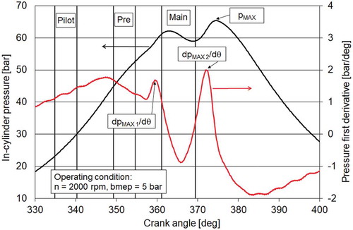
Indicating technique has been applied in different investigations made by the authors (Zamboni, Citation2018, Citation2019; Zamboni & Capobianco, Citation2013) to deepen the influence of engine sub-systems control on combustion process. To this aim, a large set of parameters can be derived from in-cylinder pressure diagrams, curves of pressure first derivative and heat release rates, as shown in Figures and .
The maximum level of pressure (pMAX) is related to the combustion of the main injection. Its position, about 15 crank angle degrees after Top Dead Centre (TDC), is due to the relevant injection timing (Figure ), more oriented to NOX lowering than to fuel consumption reduction. From the signal of pressure first derivative, two maximum levels (dpMAX1/dθ and dpMAX2/dθ) are derived. The first corresponds to the combustion of the pilot and pre injections, the second to the main injection. They are used for the evaluation of a noise indicator (Inpr (Torregrosa, Broatch, Martin, & Monelletta, Citation2007)), related to the sharp pressure rise at the start of the two events, whose definition is given in EquationEquation (7)(7)
(7) .
where n and nidle are the engine speed in the actual condition and in idling mode, respectively, while dpMAX/dθ is the maximum level of the pressure derivative calculated from the compression-expansion signal in the unfired engine, for the same intake conditions.
Figure 2. In-cylinder pressure diagram, curve of pressure first derivative and related parameters
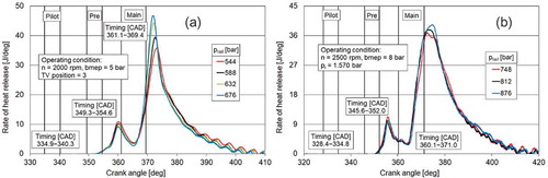
An example of rate of heat release (ROHR) curve is shown in Figure , together with two further combustion parameters, i.e., the maximum value of heat flux (ROHRMAX) and the heat released during the premixed phase of the main combustion (HRpremix). This phase ranges between the start of the main combustion and the crank angle corresponding to ROHRMAX (Badami, Mallamo, Millo, & Rossi, Citation2003). The first value is conventionally positioned at the lowest level of heat release following the combustion of pilot and pre injections.
Figure 3. Rate of heat release curve and main combustion parameters
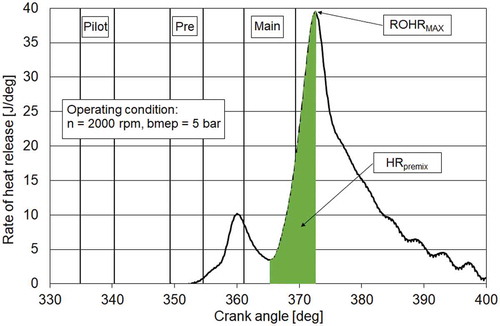
From crank angles corresponding to the release of 10%, 50% and 90% of the total heat, the centre of combustion (θ50) and the combustion duration (θ90–θ10) are also assessed. As it will be discussed in Section 3.1, the influence of rail pressure control on heat release rates is apparent through a faster combustion process during the premixed phase (Li et al., Citation2016). This effect can be quantified by calculating the maximum value of heat release first derivative and analysing the influence of rail pressure on its trend, as it will be presented in Section 3.3.
As pressure diagrams were measured in all the tested operating modes, heat release was calculated according to an in-house–developed procedure (Zamboni et al., Citation2016). Combustion parameters previously defined were therefore derived from in-cylinder pressure, pressure derivative and heat release curves. Aiming at the definition of linear relationships existing between energy, environmental, combustion and control parameters, statistical processing was then applied to the different test sets, each of them being defined by the relevant operating condition and selected values of control variables. The goal was to enlarge the outcomes of indicating technique, helping in the analysis of observed trends, and to evaluate simple correlations which may be applied for modelling and control purposes. For this reason, only the linear approach was followed.
3. Results and discussion
3.1. Influence of rail pressure control on pressure and heat release curves
Figures show in-cylinder pressure diagrams, curves of pressure first derivative and rate of heat release for operating conditions No. 2 and 3. Curves are limited to the crank angle interval related to combustion TDC (θ = 360 crank angle degrees), presenting actual timing of pilot, pre and main injections.
In order to justify the variations of observed quantities related to rail pressure control, changes in spray characteristics have to be taken into account. In Agarwal et al. (Citation2014), the behaviour of spray tip penetration (defined as the maximum axial distance of the injected spray from the injection nozzle tip) was analysed for conventional diesel oil considering four levels of injection pressure and two values of chamber pressure. Increasing injection pressure led to higher penetration of the spray tip. A second parameter was analysed (the spray area obtained by the data processing of the spray images), outlining that also the spray area enlarged when higher values of fuel injection pressure were actuated, due to the higher momentum of small droplets. This resulted in the extension of spray region due to the longer penetration of spray tip.
Another basic study is presented in Du et al. (Citation2018), where the influence of injection pressure on diesel spray development was analysed in a constant volume combustion chamber. Increasing levels of this parameter led to better atomization and evaporation of fuel droplets, reducing the combustion duration.
As a consequence, results from investigations on different engines testing conventional and alternative fuels and their blends are consistent, showing that the increase of injection pressure leads to a shorter ignition delay, a rise in peak pressure and maximum level of heat release and to a reduced combustion duration. These outcomes were observed in single cylinder, low displacement engines (Ashok, Nanthagopal, Chaturvedi, Sharma, & Thundil Karuppa Raj, Citation2018; Syed Aalam et al., Citation2016), in four cylinders naturally aspirated unit (Xu et al., Citation2018) and in a large displacement (8.8 L) engine (Imperato, Kaario, Sarjovaara, & Larmi, Citation2016). A further consequence of increased values of injection pressure was shown in Jeon & Park (Citation2018), even if at a qualitative level, where a stronger premixed combustion phase was observed, related to a faster rise of the heat release at the combustion start.
Figure 4. Influence of rail pressure on in-cylinder pressure diagrams
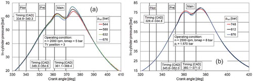
Figure 5. Influence of rail pressure on the first derivative of in-cylinder pressure
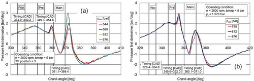
Results obtained in the present study are in line with these remarks, showing a similar influence of the injection pressure control when testing a wide range of operating modes on an engine with a different displacement. Referring to the combustion of pilot and pre injections, a slight increase in maximum pressure, dpMAX1/dθ and the relevant heat release peak was observed for lower prail values, which may be related to minor changes of intake pressure and mass flow rate. On the contrary, the main combustion was mostly influenced by rail pressure control, whose increase led to higher values of pMAX, dpMAX2/dθ and ROHRMAX. This is due to the better atomization of fuel droplets achieved with a higher injection pressure, which may be also associated with a shorter ignition delay of the main combustion (operating condition No. 2, Figures and 6). Moreover, a faster development of its premixed phase was observed (both conditions, Figures and ), as also discussed in Li et al. (Citation2016).
Figure 6. Influence of rail pressure on heat release rates
3.2. Trade-offs with NOX emission
As explained in Section 2.3, within the first phase of the investigation, a set of operating modes were identified according to variations of brake specific fuel consumption and emissions and turbocharger rotational speed within fixed targets (Zamboni et al., Citation2016). To counteract soot emissions increase, rail pressure control was added. The combustion noise indicator defined in EquationEquation (7)(7)
(7) was estimated, to check the relevant influence of injection pressure on this aspect.
Figure presents the trade-offs between brake specific NOX (bsNOX) emissions and brake specific fuel consumption (bsfc, Figure ), brake specific soot emissions (bsS, Figure ), turbocharger rotational speed (Figure ) and combustion noise indicator (Figure ) for the three tested operating conditions. All measured values were normalised, with reference to the standard mode (Step 1 in Table ) fixed by the engine manufacturer, with only the HP EGR loop activated. Table lists the values of control variables applied in each step, showing which sub-system was activated or modified.
Figure 7. Trade-offs between fuel consumption, emissions, turbocharger speed and combustion noise indicator
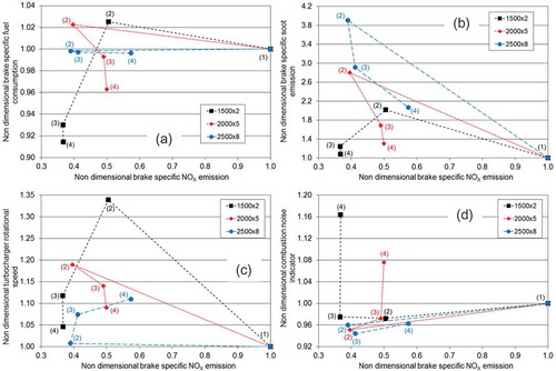
Table 6. Investigation steps
From a general point of view, the activation of LP EGR loop (Step 2) led to a strong increase of EGR rate, with a contribution from the long route loop slightly above 50% (Table ). As a consequence, negative effects were observed for soot emissions (Figure7), due to the reduction in oxygen availability (Zamboni et al., Citation2017). Fuel consumption worsened for points No. 1 and 2 (Figure7), due to the increase of engine pressure gradient and pumping losses (Zamboni et al., Citation2016, Citation2017). Referring to bsfc, this was not the case in point No. 3, due to the VNT closed-loop control, which also maintained turbocharger speed close to the reference level (Figure7). On the other hand, nTC increased with LP EGR circuit activation in the first two conditions, due to the supplemental effect of long route loop for mass flow rate. Finally, the increase in EGR rate caused the reduction of combustion noise (Figure 7).
To compensate for fuel consumption increase of Step 2 in points No. 1 and 2, open-loop VNT control was applied (Step 3). As a consequence, larger levels of VNT opening degree were obtained, also corresponding to an increase of LP proportion. In operating condition No. 2, this meant that almost the whole EGR mass flow rate was recirculated by the low-pressure circuit, with a major reduction of fEGR (from 37% to 30%). In closed-loop VNT control (point No. 3), the intake pressure was increased in Step 3 achieving an LP proportion equal to 1, with a minor change of EGR rate referring to Step 2. When considering a hybrid EGR system, a major contribution from low-pressure circuit was also highlighted in Park, Song, & Lee (Citation2015), where an optimization process was made at three speed levels aiming at the reduction of NOX emissions and fuel consumption on a 3.0-dm3 engine. The increasing role of long route EGR loop for higher engine speed and load values was as well observed in Suresh et al. (Citation2013) for a 2.8-dm3 engine.
In Step 4, the increase of rail pressure was applied in the three experimental points, as mentioned in Section 2.3.
As a consequence of the different steps, a significant reduction of bsNOX was obtained, ranging from 63.3% (1500 × 2) to 50% (2000 × 2) and 42.6% (2500 × 8). As discussed in Zamboni et al. (Citation2016, Citation2017), this is due to the increase of overall EGR rate (mainly occurring from Step 1 to Step 2) and to the prevailing contribution from the low-pressure circuit, as shown in Table . The second cause is particularly true in point No. 2, where EGR rate reduced from Step 2 to Step 3, but LP proportion changed from 0.591 to 0.922. Among the benefits related to the long route EGR, lower temperature of the intake charge and better mixing between air and recirculated gases are obtained, as a consequence of the double stage of cooling and the length of the EGR loop. Referring to rail pressure control, its increase has a negative impact on NOX emissions (Ashok et al., Citation2018; Imperato et al., Citation2016; Jeon & Park, Citation2018; Syed Aalam et al., Citation2016), due to the better fuel atomization and to the faster development of premixed combustion phase, resulting in higher peak pressure. Anyway, NOX decrease achieved in Steps 2 and 3 was larger, leading to the enhancement previously outlined.
A simultaneous decrease of bsfc was achieved in points No. 1 (−8.6%) and No. 2 (−3.7%), while a constant level was observed for point No. 3. In this case, the increase of AVNT applied in Step 3 (Table ) allowed to compensate for the changes in engine pressure gradient related to the activation of LP EGR loop, which resulted in higher pumping losses and fuel consumption (Zamboni et al., Citation2016, Citation2017). A further benefit was related to the increase of rail pressure, due to the impact on fuel atomization, mixture formation and faster combustion (Ashok et al., Citation2018; Imperato et al., Citation2016; Jeon & Park, Citation2018; Syed Aalam et al., Citation2016).
For the same reasons, rail pressure control allowed to reduce soot penalties at low load and speed (+8% in point No. 1 and +30% in point No. 2), but bsS was anyway more than doubled in operating condition No. 3. Soot increase observed in Step 2 was of course related to the rise of EGR rate and the consequent reduction of oxygen availability in the combustion chamber, as already mentioned. A first decrease of bsS was obtained in Step 3, due to the reduction of EGR rate (working condition No. 2) or to the increase of LP proportion, leading to the better mixing of air and recirculated gases (Zamboni et al., Citation2016, Citation2017) (working conditions No. 1 and 3). Then, a further benefit was related to the increased levels of rail pressure, as also reported in Ashok et al. (Citation2018), Imperato et al. (Citation2016), Jeon & Park (Citation2018), and Syed Aalam et al. (Citation2016), due to an enhanced premixed phase of combustion. Anyway, further measures are required to cut soot emissions for working points at medium levels of engine speed and load, whose impact is rising in current driving cycles and procedures for vehicles Type Approval or In-Use Compliance. In any case, VNT and rail pressure control proved to be interesting options to compensate for soot increase caused by the activation of LP circuit.
Comparing Steps 1 and 4, turbocharger rotational speed was raised between 5% and 11%, representing a positive effect for engine response in transient conditions. This result is a consequence of the increase of turbine mass flow rate related to the contribution from low-pressure EGR circuit, which positively affected turbine and compressor working conditions (Cornolti, Onorati, Cerri, Montenegro, & Piscaglia, Citation2013; Millo, Ferrero Giacominetto, & Gianoglio Bernardi, Citation2012). In points No. 1 and 2, the higher turbine mass flow rate compensated for the more opened positions of its nozzle. It has to be noticed that an opposite trend was apparent among operating conditions No. 1 and 2 and the third one, probably due to the different scheme for VNT control (open/closed loop).
As far as Inpr is concerned, the rise of injection pressure led to higher levels of this index in points No. 1 and 2, but variations look acceptable, as can be derived by Torregrosa, Broatch, Plá, & Mónico (Citation2013), where a similar indicator was analysed. For operating condition No. 3, a reduction of Inpr in mode (4) was observed, compared to the reference mode (1), which may be justified with the higher EGR rate and its influence on combustion noise (Bunce et al., Citation2011; Selim, Citation2003).
3.3. Links between rail pressure and combustion parameters
As a further outcome of the experimental investigation on rail pressure control, the availability of pressure diagrams and heat release curves allowed to calculate combustion parameters defined in Section 2.4 and verify the existing relationships with this control variable. A sample of correlations is presented in Figures , and 1, where rail pressure is always on the X-axis, while trends of the selected quantities are shown for three sets of tested modes in operating conditions No. 2 and 3. A quantitative assessment of the influence of rail pressure on selected parameters was therefore developed.
Figure shows the relationship between rail pressure and the premixed combustion phase, as the maximum rate of heat release, heat released in the premixed phase of the main combustion and the maximum level of the first derivative of heat release (always referring to main combustion) are respectively presented in the three graphs. The increasing trends of these quantities when actuating higher levels of prail, proved that the premixed phase of the combustion process is particularly affected by this control variable.
Figure 8. Link between rail pressure and combustion parameters (first group)
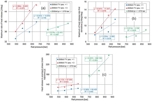
As discussed in Ashok et al. (Citation2018), Imperato et al. (Citation2016), Li et al. (Citation2016), Syed Aalam et al. (Citation2016) and Xu et al. (Citation2018), higher values of ROHRMAX (Figure ) were observed when rail pressure was increased, due to the better fuel atomization. Distribution of droplets with smaller diameters and higher spray penetration led to enhance mixture formation with a faster development of the combustion process in the first phase. This is confirmed by the trend of maximum value of heat release first derivative (Figure ), which was also observed in Jeon & Park (Citation2018). Moreover, the heat released in the premixed phase was also higher (Figure ), despite the shorter ignition delay (Figure ). In this case, the higher injection rate deriving by the rise of injection pressure probably counterbalances the faster start of combustion. In any case, HRpremix is also a consequence of the mixture formation during the ignition delay, whose enhancement was already outlined. Linear relationships with satisfactory levels of determination coefficient were found between rail pressure and combustion parameters.
Changes in premixed combustion influenced further quantities, as shown in Figure referring to the maximum pressure (Figure ) and the combustion centre (Figure ). Higher levels of peak pressure when rail pressure raised were also reported in Ashok et al. (Citation2018), Imperato et al. (Citation2016); Jeon & Park (Citation2018); Syed Aalam et al. (Citation2016) and Xu et al. (Citation2018), while θ50 moved towards the TDC. Furthermore, the whole combustion process is enhanced, as reduced levels of the combustion duration were evaluated (Figure ), again in line with other investigations (Ashok et al., Citation2018; Imperato et al., Citation2016; Jeon & Park, Citation2018; Syed Aalam et al., Citation2016; Xu et al., Citation2018). As for the first group of combustion parameters, linear relationships with a high determination coefficient were generally defined, with a few exceptions.
Figure 9. Link between rail pressure and combustion parameters (second group)
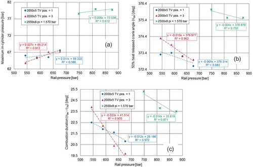
Figure presents the behaviour of parameters derived by the first derivative of pressure curves, i.e., values of its first and second maximum (Figure ,, respectively) and combustion noise indicator (Figure ). The increasing trend of the second maximum was already justified, being related to the development of the premixed phase when burning the fuel injected in the main event.
The opposite tendency of the first maximum was probably due to little variations of in-cylinder conditions affecting the combustion of pilot and pre injected quantities. Slight variations were anyway apparent for this parameter. As a consequence, in operating condition No. 2, the prevailing effect of the second maximum led to a rise of Inpr with rail pressure. For point No. 3, changes in dpMAX1/dθ and dpMAX2/dθ were balanced and quite constant levels of Inpr were observed (graph 9c).
Figure 10. Link between rail pressure and combustion parameters (third group)
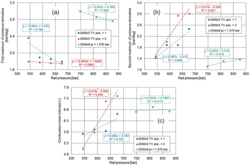
The relevant trend line has a low value of R2, while all the other correlations show a determination coefficient above 0.7. The increase of combustion noise with rail pressure is also shown in Jung et al. (Citation2016). Therefore, the selected indicator is confirmed to be a suitable parameter for this type of analysis, due to the influence of pressure rise rate on combustion noise (Jung et al., Citation2016).
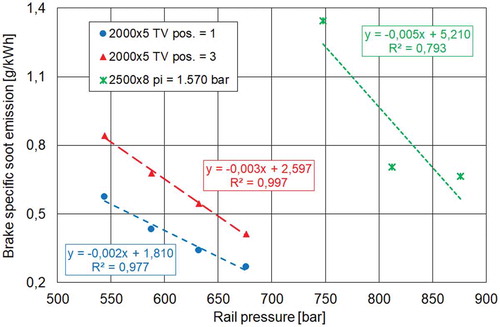
Finally, Figure is related to the link between soot emission and rail pressure. This result confirms the proper development of experimental tests with the relevant processing and calculation procedures of combustion parameters, as further relationships (i.e., bsS—HRpremix) were also verified. This outcome is related to the enhancement of premixed combustion phase, during which soot is not generated, as zones with rich mixtures in the combustion chamber are limited and pyrolysis reactions are less probable (Eastwood, Citation2008).
Figure 11. Link between rail pressure and soot emission
4. Conclusions
Fuel injection, EGR and turbocharging systems strongly characterized the development of diesel engines in the last thirty years. The investigation presented in this paper confirmed the potential of an integrated management of these sub-assemblies to achieve lower fuel consumption and raw NOX emission, with minor penalties in soot emission and combustion noise, while enhancing turbocharger performance. Further outcomes are related to the evaluation of the contribution of a prototype low-pressure EGR circuit to the overall EGR rate and to the identification of a large number of linear relationships linking energy, environmental, operating and combustion parameters to rail pressure in each tested working point.
From a quantitative point of view, referring to the standard operating mode with the activation of the HP EGR loop (corresponding to the Euro 5 phase) for each of the three-part load conditions, the main findings can be summarized as follows:
Reduction of NOX emissions between 51% and 63% were achieved through LP EGR activation and VNT/intake pressure control. As a reference, the Euro 6 phase forced a reduction of 58% for this pollutant. The increase of rail pressure showed limited effects on bsNOX in operating conditions No. 1 and 2, while the benefit was reduced from 59% to 43% at higher engine speed and load (2500 × 8).
In operating condition No. 1, an 8.6% decrease in fuel consumption was observed, with the major contribution due to VNT control. When increasing engine speed and load, a lower benefit was achieved in point No. 2 (−3.7%, mostly due to a higher level of rail pressure), while constant bsfc values were measured in point No. 3.
Soot increase was acceptable in operating conditions No. 1 and 2 (+8% and +30%, respectively). In the third point, bsS was more than doubled, even if the higher rail pressure level allowed to achieve a significant reduction. As a consequence, more frequent regeneration phases of diesel particulate filter can be expected in a real application.
Turbocharger speed was increased between 4.6% and 11%, thus granting a better transient response.
Combustion noise indicator showed higher values in points No. 1 and 2 (+16.4% and +7.6%, respectively). In this case, a further validation of the acceptability of estimated levels would require direct measurements of combustion noise. A reduction was observed in the third condition, despite the higher rail pressure, probably due to the increase of EGR rate and its smoothing effect.
Referring to the influence of rail pressure on engine parameters at fixed operating mode, the investigation allows to verify trends related to its control when considering a downsized engine fitted with a hybrid EGR system and a variable nozzle turbine. In particular, a faster development of the premixed phase of the main combustion was apparent, leading to higher values of maximum pressure and heat release, reducing ignition delay and combustion duration and shifting the centre of combustion closer to the TDC.
Considering three combustion parameters obtained from heat release curves (maximum rate of heat release, heat released in premixed phase and maximum of heat release rate first derivative), a quantitative assessment of injection pressure influence was made, representing an interesting outcome of this study.
Other effects were analysed for the first derivative of pressure signal, its maximum values and the relevant combustion index, increasing for higher rail pressure levels.
Finally, linear relationships were defined to link rail pressure and combustion quantities, proving that a simple approach can be adopted to identify the engine behaviour when fixing its operating mode, which may be useful for modelling purpose.
Nomenclature
| Notations | = | |
| bmep | = | Brake mean effective pressure |
| bsfc | = | Brake-specific fuel consumption |
| bsNOX | = | Brake-specific nitrogen oxides emission |
| bsS | = | Brake-specific soot emission |
| f | = | Mass flow fraction |
| n | = | Rotational speed |
| p | = | Pressure |
| A | = | Opening degree |
| AFR | = | Air–fuel ratio |
| CAD | = | Crank angle degree |
| CDI | = | Charge Dilution Index |
| DC | = | Duty-cycle |
| DI | = | Direct injection |
| ECU | = | Electronic control unit |
| EGR | = | Exhaust gas recirculation |
| HP | = | High pressure |
| HR | = | Heat release |
| LP | = | Low pressure |
| M | = | Mass flow rate |
| PCCI | = | Premixed Charge Compression Ignition |
| RCCI | = | Reactivity Controlled Compression Ignition |
| ROHR | = | Rate of heat release |
| S | = | Soot, nozzle ring push rod displacement |
| TDC | = | Top dead centre |
| TV | = | Exhaust throttle valve |
| VNT | = | Variable nozzle turbine |
| X | = | Volumetric concentration |
| θ | = | Crank angle |
Subscripts
| a | = | Air, ambient |
| f | = | Fuel |
| i | = | Intake |
| idle | = | Engine idling condition |
| e | = | Exhaust |
| n | = | Noise |
| pr | = | Pressure rise |
| premix | = | Premixed combustion mode |
| Rail | = | Common rail |
| EGR | = | Exhaust gas recirculation |
| HP | = | High pressure |
| LP | = | Low pressure |
| MAX | = | Maximum |
| MIN | = | Minimum |
| TC | = | Turbocharger |
| VNT | = | Variable nozzle turbine |
Additional information
Funding
Notes on contributors

Giorgio Zamboni
Giorgio Zamboni is working as a researcher in the Department of Mechanical, Energy, Management and Transportation Engineering of Genoa University, Italy. His research interests are related to internal combustion engines control, combustion analysis, biofuels application and modelling of road vehicles for energy consumption and emissions evaluation in different driving modes, also referring to hybrid and electric vehicles.
The research presented in the paper is related to an extended study on automotive diesel engines, aiming at the reduction of NOX emissions and fuel consumption through the application of integrated control strategies involving hybrid EGR systems (resulting from the simultaneous application of high and low pressure EGR circuits), turbocharger and fuel injection system. Moreover, processing of experimental database allowed the development of a tool aiming at an extended analysis of combustion process based on indicating technique and the evaluation of quantities summarising trends of in-cylinder pressure diagrams and curves of heat release.
Related Research Data
References
- Agarwal, A. K., Dhar, A., Gupta, J. G., Kim, W. I., Lee, C. S., & Park, S. (2014). Effect of fuel injection pressure and injection timing on spray characteristics and particulate size-number distribution in a biodiesel fuelled common rail direct injection diesel engine. Applied Energy, 130, 212–21. doi:10.1016/j.apenergy.2014.05.041
- Asad, U., Tjong, J., & Zheng, M. (2014). Exhaust gas recirculation – Zero dimensional modelling and characterization for transient diesel combustion control. Energy Conversion and Management, 86, 309–324. doi:10.1016/j.enconman.2014.05.035
- Asad, U., & Zheng, M. (2014). Exhaust gas recirculation for advanced diesel combustion cycles. Applied Energy, 123, 242–252. doi:10.1016/j.apenergy.2014.02.073
- Ashok, B., Nanthagopal, K., Chaturvedi, B., Sharma, S., & Thundil Karuppa Raj, R. (2018). A comparative assessment on Common Rail Direct Injection (CRDI) engine characteristics using low viscous biofuel blends. Applied Thermal Engineering, 145, 494–506. doi:10.1016/j.applthermaleng.2018.09.069
- Badami, M., Mallamo, F., Millo, F., & Rossi, E. E. (2003). Experimental investigation on the effect of multiple injection strategies on emissions, noise and brake specific fuel consumption of an automotive direct injection common-rail diesel engine. International Journal of Engine Research, 4(4), 299–310. doi:10.1243/146808703322743903
- Benajes, J., Martín, J., García, A., Villalta, D., & Warey, A. (2017). Swirl ratio and post injection strategies to improve late cycle diffusion combustion in a light-duty diesel engine. Applied Thermal Engineering, 123, 365–376. doi:10.1016/j.applthermaleng.2017.05.101
- Bunce, M., Snyder, D., Gayatri, A., Hall, C., Koehler, J., Davila, B., … Shaver, G. (2011). Optimization of soy-biodiesel combustion in a modern diesel engine. Fuel, 90, 2560–2570. doi:10.1016/j.fuel.2010.09.024
- Capobianco, M., Gambarotta, A., & Zamboni, G. (1998). Controlling turbocharging and EGR system to improve exhaust aftertreatment conditions in an automotive diesel engine. 6th International conference on turbocharging and air management systems, paper C554/004/98, London: Institution of Mechanical Engineers.
- Cornolti, L., Onorati, A., Cerri, T., Montenegro, G., & Piscaglia, F. (2013). 1D simulation of a turbocharged diesel engine with comparison of short and long EGR route solutions. Applied Energy, 111, 1–15. doi:10.1016/j.apenergy.2013.04.016
- Du, W., Lou, J., Yan, Y., Bao, W., & Liu, F. (2017). Effects of injection pressure on diesel sprays in constant injection mass condition. Applied Thermal Engineering, 121, 234–241. doi:10.1016/j.applthermaleng.2017.04.075
- Du, W., Zhang, Q., Zhang, Z., Lou, J., & Bao, W. (2018). Effects of injection pressure on ignition and combustion characteristics of impinging diesel spray. Applied Energy, 226, 1163–1168. doi:10.1016/j.apenergy.2018.06.032
- Eastwood, P. (2008). Particulate emissions from vehicles. Chichester: John Wiley & Sons Ltd.
- Imperato, M., Kaario, O., Sarjovaara, T., & Larmi, M. (2016). Influence of the in-cylinder gas density and fuel injection pressure on the combustion characteristics in a large-bore diesel engine. International Journal of Engine Research, 17(5), 525–533. doi:10.1177/1468087415589043
- Jeon, J., & Park, S. (2018). Effect of injection pressure on soot formation/oxidation characteristics using a two-color photometric method in a compression-ignition engine fueled with biodiesel blend (B20). Applied Thermal Engineering, 131, 284–294. doi:10.1016/j.applthermaleng.2017.12.005
- Johnson, T., & Joshi, A. (2018). Review of vehicle engine efficiency and emissions. SAE Technical Paper 2018-01-0329, doi:10.4271/2018-01-0329, Warrendale: SAE International.
- Jung, I., Jin, J., Lee, D., Lee, S., Yang, S., & Min, K. (2016). Closed-loop control method for monitoring and improving the diesel combustion noise, SAE Technical Paper 2016-01-1770. doi:10.4271/2016-01-1770, Warrendale: SAE International.
- Li, G., Zhang, C., & Li, Y. (2016). Effects of diesel injection parameters on the rapid combustion and emissions of an HD common-rail diesel engine fueled with diesel-methanol dual-fuel. Applied Thermal Engineering, 108, 1214–1225. doi:10.1016/j.applthermaleng.2016.08.029
- Marelli, S., Capobianco, M., & Zamboni, G. (2014). Pulsating flow performance of a turbocharger compressor for automotive application. International Journal of Heat and Fluid Flow, 45, 158–165. doi:10.1016/j.ijheatfluidflow.2013.11.001
- Mei, D., Yue, S., Zhao, X., Hielscher, K., & Baar, R. (2017). Effects of center of heat release on combustion and emissions in a PCCI diesel engine fuelled by DMC-diesel blend. Applied Thermal Engineering, 114, 969–976. doi:10.1016/j.applthermaleng.2016.12.064
- Millo, F., Ferrero Giacominetto, P., & Gianoglio Bernardi, M. (2012). Analysis of different exhaust gas recirculation architectures for passenger car diesel engines. Applied Energy, 98, 79–91. doi:10.1016/j.apenergy.2012.02.081
- Mohan, B., Yang, W., Yu, W., Tay, K. L., & Chou, S. K. (2015). Numerical investigation on the effects of injection rate shaping on combustion and emission characteristics of biodiesel fueled CI engine. Applied Energy, 160, 737–745. doi:10.1016/j.apenergy.2015.08.034
- Nazemi, M., & Shahbakhti, M. (2016). Modeling and analysis of fuel injection parameters for combustion and performance of an RCCI engine. Applied Energy, 165, 135–150. doi:10.1016/j.apenergy.2015.11.093
- Park, J., Song, S., & Lee, K. S. (2015). Numerical investigation of a dual-loop EGR split strategy using a split index and multi-objective Pareto optimization. Applied Energy, 142, 21–32. doi:10.1016/j.apenergy.2014.12.030
- Park, Y., & Bae, Y., . C. (2014). Experimental study on the effects of high/low pressure EGR proportion in a passenger car diesel engine. Applied Energy, 133, 308–316. doi:10.1016/j.apenergy.2014.08.003
- Selim, M. Y. E. (2003). Effect of exhaust gas recirculation on some combustion characteristics of dual fuel engine. Energy Conversion and Management, 44, 707–721. doi:10.1016/S0196-8904(02)00083-3
- Suresh, A., Langenderfer, D., Arnett, C., & Ruth, M. (2013). Thermodynamic systems for tier 2 bin 2 diesel engines. SAE International Journal of Engines, 6(1), 167–183. doi:10.4271/2013-01-0282
- Syed Aalam, C., Saravanan, C. G., & Prem Anand, B. (2016). Impact of high fuel injection pressure on the characteristics of CRDI diesel engine powered by mahua methyl ester blend. Applied Thermal Engineering, 106, 702–711. doi:10.1016/j.applthermaleng.2016.05.176
- Thangaraja, J., & Kannan, C. (2016). Effect of exhaust gas recirculation on advanced diesel combustion and alternate fuels – A review. Applied Energy, 180, 169–184. doi:10.1016/j.apenergy.2016.07.096
- Torregrosa, A. J., Broatch, A., Martin, J., & Monelletta, L. (2007). Combustion noise level assessment in direct injection diesel engines by means of in-cylinder pressure components. Measurement Science and Technology, 18, 2131–2142. doi:10.1088/0957-0233/18/7/045
- Torregrosa, A. J., Broatch, A., Plá, B., & Mónico, L. F. (2013). Impact of Fischer-Tropsch and biodiesel fuels on trade-offs between pollutant emissions and combustion noise in diesel engines. Biomass and Bioenergy, 52, 22–33. doi:10.1016/j.biombioe.2013.03.004
- Working Group 1 of the Joint Committee for Guides in Metrology. (2008, September). Evaluation of measurement data – Guide to the expression of uncertainty in measurement. JCGM 100, First edition. Retrieved from http://www.bipm.org
- Xu, L., Baib, X., Jiac, M., Qiana, Y., Qiaoa, X., & Lu, X. (2018). Experimental and modeling study of liquid fuel injection and combustion in diesel engines with a common rail injection system. Applied Energy, 230, 287–304. doi:10.1016/j.apenergy.2018.08.104
- Yoon, S. K., Ge, J. C., & Choi, N. J. (2019). Influence of fuel injection pressure on the emissions characteristics and engine performance in a CRDI Diesel engine fueled with palm biodiesel blends. Energies, 12, 3837. doi:10.3390/en12203837
- Zamboni, G. (2018). A study on combustion parameters in an automotive turbocharged diesel engine. Energies, 11(10), 2531. doi:10.3390/en11102531
- Zamboni, G. (2019). Influence of fuel injection, turbocharging and EGR systems control on combustion parameters in an automotive diesel engine. Applied Sciences, 9(3), 484. doi:10.3390/app9030484
- Zamboni, G., & Capobianco, M. (2013). Influence of high and low pressure EGR and VGT control on in-cylinder pressure diagrams and rate of heat release in an automotive turbocharged diesel engine. Applied Thermal Engineering, 51, 586–596. doi:10.1016/j.applthermaleng.2012.09.040
- Zamboni, G., Moggia, S., & Capobianco, M. (2016). Hybrid EGR and turbocharging systems control for low NOX and fuel consumption in an automotive diesel engine. Applied Energy, 165, 839–848. doi:10.1016/j.apenergy.2015.12.117
- Zamboni, G., Moggia, S., & Capobianco, M. (2017). Effects of a dual-loop EGR system and VNT control on the operating parameters of an automotive diesel engine. Energies, 10(47), 47. doi:10.3390/en10010047