
 ?Mathematical formulae have been encoded as MathML and are displayed in this HTML version using MathJax in order to improve their display. Uncheck the box to turn MathJax off. This feature requires Javascript. Click on a formula to zoom.
Abstract
Design and simulation of air-solar-finned reheating unit, an innovative design of a parabolic trough solar collector (PTSC) has been demonstrated in this work. Fundamentally, the design equations were formulated on the optical and thermal principles. The fundamental optical equations were transformed and equated with the original optical equations to realize the optical design functions. The design variables appear in the design function as the unknowns. The design functions were differentiated with respect to the design variables to form design simulatory matrices. Prior to the simulation, the design functions were made to approach zero by the introduction of convergent factors which guarantee the convergence of the simulatory matrices whose final output defines the design variables. The design was algorithmized with a flowchart to justify the design procedures. A slight obtuse-angled rim design was adopted in the design of the reheating unit (RU) which yielded optimum; rim angle of 94°, collector, optical and thermal efficiencies of 0.44, 0.72 and 0.31, respectively, and an optimum exit fluid temperature of C sequel to the simulation of the design equations. Besides, the apparent tradeoffs among the design variables were useful in making design decisions. Considering the pitfalls of the traditional acute-angled rim design (AARD), the present work is advocating for the adoption of slight obtuse-angled rim design (SOARD) technique which will shield the PTSCs from the misalignment issues and equally minimize the thermal losses prone to the acute-angled rim design technique. Also, premium on material selection is recommended for the effective operation of RU.
PUBLIC INTEREST STATEMENT
The design of parabolic trough collector (PTSC) falls into three facets; the acute-angled rim design, which the focal distance is above the aperture axis and equally greater than the trough’s height, the right-angled rim design, which the focal distance lies on the aperture axis and equal to trough’s height, and the obtuse-angled rim design, which the focal distance is below the aperture axis and less than the trough’s height. The first two facets of the designs are prone to misalignment problems and colossal thermal losses. However, the third design facet is not vulnerable to the aforementioned problems but cannot raise the temperature of heat transfer fluid as the first two design facets. Strategically, the present design adopts slight obtuse-angled rim design (SOARD) and finning the reheating unit (innovative PTSC); to enhance heat transfer without impairing the efficiencies. Based on the enormous advantages associated with SOARD, it is recommended for industrial application.
1. Introduction
The planet Earth is cosmically supplied with enough electromagnetic radiation or wave energy to support the terrestrial life. However, the technological quests and advancement are demanding more energy than supported by the nature. Thus, mankind is seriously searching for the different ways of concentrating the electromagnetic radiation on the planet Earth to provide the technological and domestic energy demands (Abadal et al., Citation2014; Gwania et al., Citation2015). One of the ways of exploiting more energy from the sun is through the helio-thermal process via the application of solar concentrators; the parabolic, compound and dish troughs solar collectors.
Therefore, having the in-depth knowledge of the physics, thermodynamics and heat transfer principles of the smart technologies and efficient processes of harnessing solar energy and subduing all odds associated with the technology is vital for exploiting more energy from the sun (Siqueira et al., Citation2014; Upadhyay et al., Citation2019). This has been the concern of recent researches in the renewable energy field. In alliance, the present work is aimed at designing a reheating unit (a parabolic trough solar collector, PTSC), which serves the thermodynamic purpose of raising the temperature of heat transfer fluid (HTF; air at <60°C) from an adjoining preheating unit (flat-plate solar collector, FPSC) to a higher temperature (>100°C), which is appropriate for drying highly moisturized agricultural products (Macedo-Valencia, Citation2014). Conventionally, concentrating power farm with HTF of high thermodynamic storage capacity (water) can raise steam of high temperature for electricity generation in order to satisfy the industrial and domestic power requirements without posing any significant threats to the environment (Kumar et al., Citation2013; Tijani & Bin Roslan, Citation2014). According to Abdelhady et al. (Citation2017), there are three types of solar concentrators employed in hi-tech exploitation of electromagnetic radiation; the parabolic troughs, power towers and parabolic dishes. Effectively, the parabolic trough is widely used in exploiting the electromagnetic radiation because of the commensurate efficiency of the trough with a high HTF temperature (Abbood & Mohammed, Citation2019; Ghodbane & Boumeddane, Citation2018; Izweik et al., Citation2016; Tijani & Bin Roslan, Citation2014).
A prudent survey of literature has shown that the design of the parabolic trough concentrator could be influenced by the size of the rim angle, which categorizes the trough designs; the acute-angled rim design (AARD), the right-angled rim design (RARD) and obtuse-angled rim design (OARD) of a parabolic trough solar collector (PTSC). Systematically, the acute-angled rim design is characterized with a flattened trough (the focal distance is greater than the height of the trough) with an elevated focal distance above the aperture axis of the PTSC. Equitably, the right-angled rim design has the focal distance equal to the height of the PTSC with the focal point coinciding with the aperture axis of the PTSC. Practically, the obtuse-angled rim design is characterized by a depressed focal distance below the aperture axis of the PTSC with the height of the trough greater than the focal distance. Aphoristically, the depth of the depression for the same aperture size is governed by the height of the trough; the more the height of the trough, the more the focal point is depressed towards the apex of the trough and vice versa. Notably, the following workers (Abdelhady et al., Citation2017; Gaitan, Citation2012; Sup et al., Citation2015) have adopted the acute-angled rim design approach in the design and performance analysis of the parabolic trough, this facet of design and performance analysis is susceptible to significant convectional heat loss due to the free flow of wind around the elevated absorber and if the absorber tube is not properly enveloped with a glass tube, the efficiency of the collector is surely retarded. In retrospect, they recorded the following collector design efficiencies of 0.65 and 0.70, respectively. Classically, other researchers (Ghodbane & Boumeddane, Citation2018; Kumar et al., Citation2013; Mohamed, Citation2013; Montesa et al., Citation2013) applied the right-angled rim design technique, which incurs less convectional thermal loss since the trough partially screens the absorber from the cooling effect of the winds. Consequently, they declared several collector design efficiencies of 0.37, 0.60, 0.61, and 0.71, respectively. Irrespective of the difference in the design techniques, the design efficiency published by Abdelhady et al. (Citation2017) is in concordance with those of Montesa et al. (Citation2013), and Ghodbane and Boumeddane (Citation2018). Similarly, the collector design efficiencies by Gaitan (Citation2012) and Kumar et al. (Citation2013) equally concurred with each other despite the difference in the design methodologies. However, Mohamed (Citation2013) collector efficiency disagrees with the results achieved by both techniques; acute-angled rim design and right-angled rim design methods. Probably, the difference in the design yardsticks could be attributed to the difference in the capacity of their troughs and prevailing environmental conditions. However, Mohamed (Citation2013) is outstanding in the sense that moderate collector efficiency (0.37), which indicates that the thermal efficiency is significant or higher exit fluid temperature could be attained compared to design efficiency (>0.60), which optical efficiency dominates. Based on the literature survey a good design of PTSC should preserve both optical and thermal efficiencies, which is feasible by careful design of the focal distance and the height of the trough. Notably, the three facets of the design of the reheating unit (PTC) as reviewed in the literature were carried out without a simulator, which does not encourage a tradeoff among the design variables and could limit the performance of the reheating unit (PTC). However, the present work is pivoted on a simulatory design technique to ensure proper tradeoff among the design variables, which engenders optimum optical and thermodynamic performance of the reheating unit (PTC).
Characteristically, Macedo-Valencia et al. (Citation2014) pivoted their design on the obtuse-angled rim criterion thereon the height of the trough is greater than the focal distance and the absorber is totally screened by the trough against the wind flow on evacuating the trough with a glass cover, the risk of thermal loss becomes negligible. However, the more concentration ratio is gained with the extreme obtuse-angled rim compared to the right-angled rim and acute-angled rim design techniques. Pertinently, Macedo-Valencia et al. (Citation2014) recorded collector design efficiencies ranging from 0.3649 to 0.5057, which are in alignment with that of Mohamed (Citation2013). Generally, the differences in the collector design efficiencies reviewed could be strongly attributed to the differences in the design considerations and locations. The present work is fascinated by the exclusive advantages of obtuse-angled rim design to adopt the slight obtuse-angled rim design (SOARD) technique in the design and simulation of the parabolic trough solar collector (PTSC). Moreover, the aim of the present design is to diversify the application of PTSC to hi-tech drying technology, by substituting the heat transfer fluid (HTF; water) in the conventional PTSC designs with air (Huanga et al., Citation2016). Superficially, this idea may appear to be impracticable using air as the HTF, which has a lower thermal storage capacity, but can be directly used in drying operation. However, the application of air as the HTF with a low thermal storage capacity will be ameliorated by loading the absorber with a lot of fins, which obviously reduce the cross-sectional area available to the HTF and enhance the heat transfer phenomenon between the finned absorber and HTF. Thus, the reduction in mass flowrate of HTF engenders a rise in the exit fluid temperature of the HTF (air), which could be employed in the direct drying operation. Therefore, the present design considers; the application of finned absorber in lieu of unfined absorber, the use of air as the HTF against water and the adoption of slight obtuse-angled rim design (SOARD) technique in the bid to raise the temperature of HTF (>100°C) and to achieve substantial collector and thermal efficiencies (>0.30) through the formulations and simulations of the design equations.
Furthermore, emphasis is laid on the selection of premium materials for the optimum performance of the finned absorber and in the selection of trough material with a high reflectivity to enhance the illumination and concentration of solar irradiance on the finned absorber (Ricardo, Citation2011). Essentially, the present work is algorithmized both in design and simulation processes, which distinguish it from other designs in the literature.
Subsequently, other sections of this paper will include; materials and method articulated in a flow chart, further characterized with the formulation of design equations and their simulations, presentation of results and their discussion, and lastly, conclusions and recommendations.
2. Materials and method
The design of the reheating unit is adapted to the following methodologies:
The design functions or equations were formulated on the fundamental (optical or thermal) principles. The design variables were identified and incorporated into the design functions or equations and parameters as the unknown (symbolic) variables.
The simulatory matrices were made of the coefficient (n × n) matrix and column (n × 1) matrix whose elements were pivoted on the partial derivatives of the design functions or equations with respect to the design variables (the unknowns) and the design functions, respectively.
Then, the initialization of values of the design variables and the provision of other essential input data was insightfully done to prepare the simulation process. Prior to the simulation, a check on the convergence of the design functions has to be carried out; to ascertain whether they are approaching zero or not (which is an inevitable design condition). Once there is a tendency of convergence, the simulation is then executed. Otherwise, the odd or nonconvergent terms of the design functions are identified and multiplied with the convergent factors such that the design functions have the propensity to approach zero or stand a chance of being converged. Consequently, the simulation is characterized with a quick convergence as the convergence criterion is readily attained. The optimal design variables are commensurate with the final output values that are capable of making the design functions to naturally approach zero.
Thus, the design approach is strongly based on the multiple input and multiple output (MIMO) approach, which is appropriate for system design (Stoecker, Citation1989) rather than on single input and single output (SISO) technique that may not guarantee significant harmony among the design variables for the optimum performance of the designed system. The entire process or procedure is carefully algorithmized in Figure .
Figure 1. Optical design flowchart.
2.1. Formulation of optical design equations
Technically, the design equations are to be governed by optical and thermal behaviours of the parabolic trough solar collector (PTSC). The optical characteristics of the PTSC are expected to influence the thermal characteristics of the PTSC. Thus, the overall or collector efficiency of the system (PTSC) is defined as an attenuated difference in the efficiencies; optical and thermal. The attenuation factor is equivalent to the heat removal factor. Algorithmically, the optical design is illustrated in Figure , the optical design flowchart describing the design sequence.
The focal point (fpt (m)), the aperture or the width of the parabolic trough solar collector (wpt (m)) and the height (hpt (m)) between the apex and the rim of the parabolic trough collector is expressed in (Abdelhady et al., Citation2017; Borah et al., Citation2013; Ghodbane & Boumeddane, Citation2018; Pavlović et al., Citation2014) as
where is the first optical design function.
The radius of a circle, Rpt whose centre is at (0, 0) and having intercepts at (0.5wpt, (hpt-fpt)) could be approximated to the rim radius (Barone et al., Citation2019; Ghodbane & Boumeddane, Citation2018; Kalogirou, Citation2009) of the trough in EquationEquation (2)(2)
(2) as
Transforming with EquationEquation (1)(1)
(1) gives
where is the second optical design function.
The internal surface area of the parabolic trough collector As,pt (m2) is given in EquationEquation (3)(3)
(3) by Macedo-Valencia et al. (Citation2014) as
The present work presents a transform of Macedo-Valencia et al. (Citation2014) as
The rim angle of the parabolic trough collector, ψr (degrees) is defined in EquationEquation (4)(4)
(4) according to (Abdelhady et al., Citation2017; Alfelleg, Citation2014; Mohamed, Citation2013; Macedo-Valencia et al., Citation2014) in EquationEquation (4)
(4)
(4) as
but the present work redefines the rim angle as
Considering equality in both definitions of rim angle, results in a third independent optical design equation,
where Rpt (m) is the parabolic radius of curvature.
The geometrical concentration ratio (CR) is expressed in EquationEquation (5)(5)
(5) (Ghodbane & Boumeddane, Citation2018; Kuo et al., Citation2014; Lovegrove & Pye, Citation2012; Macedo-Valencia et al., Citation2014)
according to the present work, CR is defined as
where dab (m) is the outer diameter of the absorber.
The optical efficiency, ηopt (-) is given in EquationEquation (6)(6)
(6) (Alfelleg, Citation2014; Pierucci et al., Citation2014; Vasquez, Citation2011)
where ρpt (-) is the reflectance of the polished surface of the parabolic trough, τg (-) is the transmissivity of the glass cover, αab (-) is the absorptivity of the absorber pipe, γ (-) is the alignment or intercept factor of the absorber pipe (γ ≤ 1), κ (θi) is the incidence angle modifier and χend (-) is the end loss defined by Alfelleg (Citation2014), Kuo et al. (Citation2014) in EquationEquation (7)(7)
(7) as
and according to Alfelleg (Citation2014) the incidence angle modifier, κ(θi) in EquationEquation (8)(8)
(8) is correlated as
According to Dudley et al. (Citation1994) κ(θi) in EquationEquation (9)(9)
(9) is given as
Goswami and Kreith (Citation2008) proposed the incidence angle modifier in EquationEquation (10)(10)
(10) as
Similarly, Kalogirou (Citation2004) defined κ(θi) in EquationEquation (11)(11)
(11) as follows:
In the same vein, Montes et al. (Citation2009) presented κ(θi) in EquationEquation (12)(12)
(12) as
The concentrated solar power in EquationEquation (13)(13)
(13) is given as
whereas the directly absorbed or non-concentrated solar power in EquationEquation (14)(14)
(14) is defined as
The subscript g represents the glass cover.
The total solar power absorbed, Qsol,ab (W) is expressed as
The subscripts con, ncon and g designate the concentrated, non-concentrated heat on the absorber and the glass, respectively.
2.1.1. The Simulation of the optical design equations
The optical functions; gop1, gop2, and gop3 (in EquationEquations (1)(1)
(1) , (Equation2
(2)
(2) ) and (Equation4
(4)
(4) ), respectively, are differentiated with respect to fpt, hpt and wpt, respectively, leading to the optical simulatory matrices in EquationEquation (16)
(16)
(16) :
The detailed partial derivative of EquationEquation (16)(16)
(16) is presented in the supplementary file. The future values of the optical design variables and present values are defined in EquationEquation (17)
(17)
(17) as follows:
The final optical design variables are established the moment the set convergence criterion
() in EquationEquation (18)
(18)
(18) is satisfied
2.2. The formulation of the thermal design equations
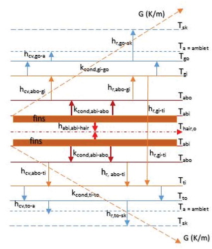
The thermal analysis of the PTSC is illustrated in Figure with the symmetric thermal gradients and fluxes (conduction, convection and radiation) from the absorber through ambient to the sky. Basically, the conduction flux is defined by Fourier’s first law of conduction, the convection flux is governed by Newton and Fourier’s law, whereas the radiation flux is based on Stefan radiation laws (Cheng & Fujii, Citation1998).
The thermal balance on the glass cover (g) is based on the steady state assumption, which gives the first independent thermal design equation in EquationEquation (19)(19)
(19) as
Similarly, the thermal balance on the absorber (ab) gives the second independent thermal design equation in EquationEquation (20)(20)
(20)
Also, the thermal balance on the parabolic trough collector (t) is represented in EquationEquation (21)(21)
(21) provides the third independent thermal design equation in EquationEquation (21)
(21)
(21)
Figure 2. Temperature gradients and thermal fluxes across the parabolic trough solar collector for the thermal analysis.
Adding EquationEquations (19)(19)
(19) and (Equation21
(21)
(21) ) or summing the thermal power functions; gth1 and gth3 gives the fourth independent thermal design equation in EquationEquation (22)
(22)
(22)
Hypothetically considering the equality of thermal conduction and convection on the absorber and heat transfer fluid, respectively, gives the fifth independent thermal design equation in EquationEquation (23)(23)
(23)
Pertinently, subtracting EquationEquation (23)(23)
(23) from EquationEquation (20)
(20)
(20) or thermal power function gth5 from gth2 yields the sixth independent thermal design equation in EquationEquation (24)
(24)
(24)
Also, considering the effectiveness of the absorber, the seventh independent thermal design equation is obtained in EquationEquation (25)(25)
(25)
where is the effectiveness of the absorber,
(kg/m3) is the density of air,
(kJ/kg) is the specific heat capacity of air,
(m/s) is internal air velocity,
(-) is the number of rectangular fins,
(m) is the thickness of the fins,
(m) is the length of the fins and
(m) is the width of the fins. The variables in EquationEquations (19)
(19)
(19) to (25) are defined as follows:
The outer surface area of the air-solar-finned absorber pipe, in EquationEquation (26)
(26)
(26) is computed as
The inner surface area of the air-solar-finned absorber pipe, in EquationEquation (27)
(27)
(27) is determined as
The cross-sectional area of the air-solar-finned absorber, available to conduction is designed in EquationEquation (28)
(28)
(28) as
The outer and inner surface areas of the glass cover (glaze) and
, respectively, are geometrically defined in EquationEquation (29)
(29)
(29) as
The inner surface area of the parabolic trough collector, is given in EquationEquation (30)
(30)
(30) as
The outer surface area of the parabolic trough collector, is given in EquationEquation (31)
(31)
(31) as
The convective heat transfer coefficient, between the outer glass (go) and ambient (a) is expressed in EquationEquation (32)
(32)
(32) as follows (Hammami et al., Citation2017; Nnamchi et al., Citation2020; Oko, Citation2011):
The radiative heat transfer coefficient, between the outer glass (go) and sky (sk) is given in EquationEquation (33)
(33)
(33) as (Kreith et al., Citation2000; Nnamchi et al., Citation2020; Oko, Citation2011)
The convective heat transfer coefficient, between the periphery of the absorber (abo) and inner glass (gi) is specified in EquationEquation (34)
(34)
(34) as (Ali & Sadek, Citation2018; Hammami et al., Citation2017; Nnamchi et al., Citation2020; Rincón-Casado et al., Citation2017)
The radiative coefficient, between the periphery of the absorber (abo) and inner glass (gi) is defined in EquationEquation (35)
(35)
(35) as (Kreith et al., Citation2000; Nnamchi et al., Citation2020; Oko, Citation2011)
The radiative coefficient, between the inner; glass (gi) and parabolic trough collector (ti) and is well defined in EquationEquation (36)
(36)
(36) as (Kreith et al., Citation2000; Nnamchi et al., Citation2020; Oko, Citation2011). Introduction to heat transfer: an algorithmic approach.
The convective heat transfer coefficient, between the periphery of the absorber (abo) and inner trough (ti) is empirically correlated in EquationEquation (37)
(37)
(37) as (Ali & Sadek, Citation2018; Nnamchi et al., Citation2020; Rincón-Casado et al., Citation2017)
The radiative heat transfer coefficient, between the periphery of the air-solar-finned absorber (abo) and the inner trough (ti) is given in EquationEquation (38)
(38)
(38) as follows (Kreith et al., Citation2000; Nnamchi et al., Citation2020; Oko, Citation2011):
The radiative coefficient, between the inner absorber (abi) and hot air stream (hair) is precisely defined in EquationEquation (39)
(39)
(39) as (Ali & Sadek, Citation2018; Hammami et al., Citation2017; Nnamchi et al., Citation2020)
The convective heat transfer coefficient, between the periphery of the parabolic trough collector (to) and the ambient (a) is obtained by considering the wind velocity to be one third of its velocity in the windward direction according to (Nnamchi et al., Citation2020) EquationEquation (40)
(40)
(40)
The radiative heat transfer coefficient, between the periphery of the parabolic trough collector (to) and the sky (sk) is expressed in EquationEquation (41)
(41)
(41) as (Kreith et al., Citation2000; Nnamchi et al., Citation2020; Oko, Citation2011)
2.2.1. Simulation of thermal design equations
Similarly, the thermal design functions; gth1(W), gth2(W), gth3(W), gth4(W), gth5(W), gth6(W) and gth7 are differentiated with respect to temperatures; Tgo(K), Tgi(K), Tabo(K), Tabi(K), Tti(K) and Tto(K) and Thair (K), respectively, resulting in the simulatory matrices in EquationEquation (42)(42)
(42)
Essentially, the thermal design procedure is akin to that of the optical design flowchart in Figure except that the thermal design variables are seven against the three optical design variables.
Also, the detailed partial derivative of EquationEquation (42)(42)
(42) is given in the supplementary file. The future values of the thermal design variables and the present values are defined in EquationEquation (43)
(43)
(43) as
The final thermal design variables are established once the set convergent criterion () in EquationEquation (44)
(44)
(44) is attained
In accordance with Abbood and Mohammed (Citation2019), Macedo-Valencia (2014) and Alfelleg (Citation2014) the thermal efficiency of the air-solar-finned PTC, ηth (-) is stated in EquationEquation (45)(45)
(45) as
The overall collector efficiency in EquationEquation (46)(46)
(46) is approximated as the difference between the attenuated optical and thermal efficiencies, which is in concordance with Mohamed (Citation2013) findings (0.3649 ≤
≤ 0.5057)
2.3. Design of the air-solar-finned absorber
According to Nnamchi et al. (Citation2020); the fin length, is expressed as a function of the outer diameter of the air-solar-finned absorber in EquationEquation (47)
(47)
(47)
Also, Nnamchi et al. (Citation2020) the fin width, designed as a function of the outer diameter of the air-solar-finned absorber in EquationEquation (48)
(48)
(48)
In the same vein, the number of fins, is related to the outer diameter of the air-solar-finned absorber in EquationEquation (49)
(49)
(49) according to Nnamchi et al. (Citation2020) as
The design, formulation of the three facets of the designs (optical, thermal and fin) is covered in EquationEquations (1)(1)
(1) to (49); the optimum design variables of the trio-designs on the specification of the design input data are given in EquationEquations (18)
(18)
(18) , (Equation44
(44)
(44) ) and (Equation46
(46)
(46) –Equation49
(49)
(49) ), respectively.
3. Results and discussion
The results comprise pertinent tables and informative graphs which are germane to discussion.
3.1. Results presentation
Apparently, some of input data were originated from the existing design data (Mohamed, Citation2013); thus, they were not arbitrarily set. Moreover, the tradeoffs among the design variables guided in the selection of the final design input data, which were subjected to an overall tradeoff in the simulatory matrices (EquationEquations (16(16)
(16) and Equation42
(42)
(42) )) leading to the final design variables.
Tables – inclusively contain the design input data and the output results; Precisely, Table holds the input data for optical design equations (EquationEquations (1(1)
(1) )–(15)), Table contains the input data for thermal design equations (EquationEquations (16
(16)
(16) )–(46)), Table encompasses the physical characteristics of the PTSC, Tables and cover the simulated optical and thermal design variable results. The output results were engaged in EquationEquation (46)
(46)
(46) to determine the collector efficiency of 0.44 based on the slight obtuse-angled rim design.
Table 1. Input data to the optical design equations
Table 2. Input data to the thermal design equations
Table 3. Physical characteristics of the parabolic trough solar collector (PTSC)
Table 4. The simulated results of the optical design variables
Table 5. The simulated results of the thermal design variables
Deeply, Figures –1 give insight into the design results by revealing the influence of design variables on the key design parameters (optical efficiency, thermal efficiency, rim angle, and concentration ratio). Sequentially, Figure shows the dependency of optical efficiency on the incidence angle and the design was pivoted on the minimum incidence angle. Figure portrays the reliance of optical efficiency on the rim angle and aperture. Figure indicates the reliability of optical efficiency on the aperture and the height of the trough. Figure presents the dependence of optical efficiency on the concentration ratio and absorber outer diameter. Figure depicts the sensitiveness of concentration ratio of the aperture and absorber sizes. Figure describes the dependency of rim angle on the focal distance and height of the trough. Figure exhibits the responsiveness of rim angle on the aperture and focal distance. Figure shows the sensitivity of thermal efficiency on the solar irradiance and aperture area.
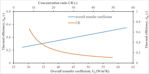
Figure displays the susceptibility of thermal efficiency on the exit fluid temperature and inlet fluid temperature; Figure explains the susceptibleness of thermal efficiency on the absorber inner diameter and HTF velocity; Figure expounds the response of exit fluid temperature on the solar irradiance and aperture area; Figure explains the reaction of exit fluid temperature on the HTF velocity and absorber diameter and lastly, Figure shows the dependency of thermal efficiency on the overall heat transfer coefficient and the concentration ratio.
The main objective of every design is to increase the efficiency or performance of the systems. Individually, Figures –1 give a clearer picture on how to achieve the premium values of the four design parameters (optical efficiency, thermal efficiency, rim angle, and concentration ratio).
Clearly, Figure shows that the maximum optical efficiency (0.719355) could be attained when the incidence angle, which is the angle between the sun ray and normal from the trough is zero; thus, the slight obtuse angle rim design of the present work was carried out at zero incidence angle which coincides with 12:00noon.
Vividly, Figure indicates the ephemeral tradeoff between the aperture and rim angle in the bid to maximize the optical efficiency. The intercept of the two curves may not be the true balance until overall superposition is carried out. Similarly, Figure presents a tentative tradeoff between the aperture and the height of the trough in an attempt to maximize the optical efficiency. Figure presents a zero tradeoff between the absorber outer diameter and concentration ratio (the relative area of the aperture to the surface area of the absorber) in an endeavour to optimize the optical efficiency. The step size change in Figure indicates the point at which further increment in both variables amounts to drastic drop in the optical efficiency. Moreover, the transition points coincide with the design output variables. Alike, Figure depicts a momentary tradeoff between the aperture and the height of the trough (the distance between the rim and the apex of the trough) in striving to enhance the concentration ratio.
In the same vein, Figure represents a brief tradeoff between the height of the trough and focal distance (a point of convergence of infinite sun rays) in a stride to boost the rim angle. Likewise, Figure epitomizes a transitory tradeoff between the focal distance and aperture (the distance between the rims) in an advance to increase the rim angle (the angle between the focal axis and rim).
Contrarily, the design variables in Figures –1 absolutely lack tradeoff with respect to thermal efficiency. Systematically, Figure depicts the noncompeting and the inverse behaviour of aperture area and solar irradiance with respect to thermal efficiency. The absence of equilibrium in Figure is because both variables form the denominator of the thermal efficiency and cannot compete against each other.
Precisely, Figure describes none competing and the apparent convergence behaviour of exit fluid temperature and inlet fluid temperature with respect to thermal efficiency. The absence of equilibrium in Figure 11is because both variables appear in the numerator of the thermal efficiency and the inlet fluid temperature can never equalize the exit fluid temperature; otherwise, the thermal efficiency becomes zero.
Specifically, Figure designates none challenging and progressive behaviour of internal air velocity and an absorber cross-section with respect to thermal efficiency. The absence of equilibrium in Figure is because both variables form the numerator of the thermal efficiency and cannot compete against each other.
Explicitly, Figure defines none opposing and progressive behaviour of aperture area and solar irradiance with respect to exit fluid temperature. The nonexistence of equilibrium in Figure is because both variables form the denominator of the thermal efficiency. Thus, they cannot compete against each other.
Similarly, Figure expresses none contending and inverse behaviour of internal fluid velocity and absorber cross-section with respect to exit fluid temperature. The absence of equilibrium in Figure is because both variables form the denominator of the thermal efficiency. Thus, would not compete against each other.
Contrarily, Figure delineates a tradeoff between the overall heat transfer coefficient and concentration ratio with respect to thermal efficiency. Hence, the emerging of equilibrium in Figure signifies that tradeoff sets in if the design variables are separated in the denominator and the numerator of the objective function. Notably, the optical design and performance of PTSC influence the thermal performance through the concentration ratio. Remarkably, high concentration ratio diminishes the thermal efficiency and vice versa.
Collectively, the optimum values corresponding to the fleeting balance in Figures –, – may not hold as a result of internal conflicts or competition among the design variables leading to a final tradeoff among the design variables. Practically, the ultimate tradeoff among the design variables is manoeuvred by the optical and thermal simulatory matrices at the point of convergence of each simulation. Pertinently, the design was made feasible by the introduction of optical (Γs) and thermal Convergent factors (Ψs) in Tables and , respectively.
3.1.1. Design input data
Tables – furnish the absolute input data required for both optical and thermal simulations in EquationEquations (16)(16)
(16) and (Equation42
(42)
(42) ), respectively:
Figure 3. Dependency of optical efficiency on the incidence angle.
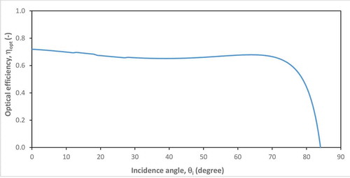
Figure 4. Reliance of optical efficiency on the rim angle and aperture.
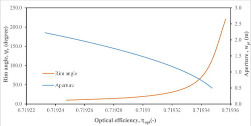
Figure 5. Reliability of optical efficiency on the aperture and height of the trough.
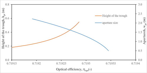
Figure 6. Dependence of optical efficiency on the concentration ratio and absorber outer diameter.
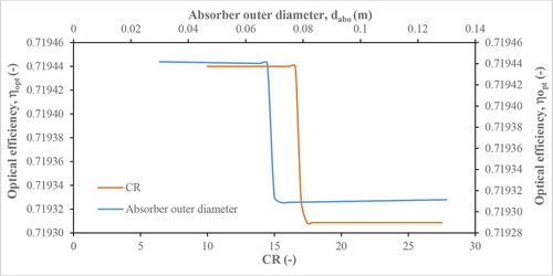
Figure 7. Sensitiveness of concentration ratio of the aperture and absorber sizes.
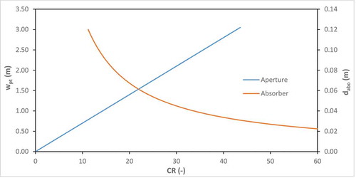
Figure 8. Dependency of rim angle to the focal distance and height of the trough.
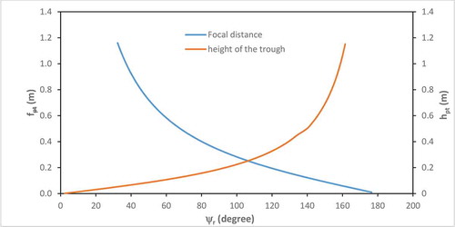
Figure 9. Responsiveness of rim angle of the aperture and focal distance.
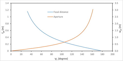
Figure 10. Sensitivity of thermal efficiency on the solar irradiance and aperture area.
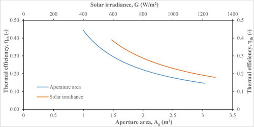
Figure 11. Susceptibility of thermal efficiency on the exit fluid temperature and inlet fluid temperature.
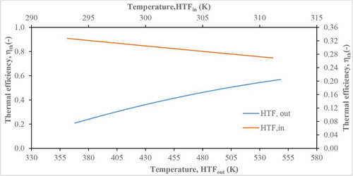
Figure 12. Susceptibleness of thermal efficiency on the absorber inner diameter and HTF velocity.
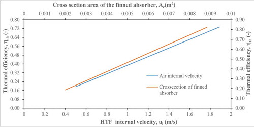
Figure 13. Response of exit fluid temperature on the solar irradiance and aperture area.
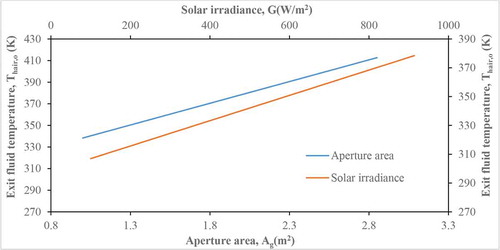
Figure 14. Reaction of exit fluid temperature on the HTF velocity and absorber diameter.
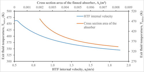
Figure 15. The Effect of concentration ratio and overall heat transfer coefficient on the thermal efficiency.
3.2. Discussion
Generally, the collector efficiency is dependent on the heat removal factor, the optical and thermal efficiencies, it is worthy of noting that as the collector efficiency approaches the optical efficiency; then, the thermal efficiency becomes insignificant and this phenomenon occurs. When the concentration ratio is very high and the overall heat transfer coefficient (thermal conductance) balances heat transport resistance. Thus, the obtuse-angled rim design ought to be developed with a small rim angle such that the thermal component of the collector efficiency is preserved and the exit fluid temperature equally raised according to Mohamed (Citation2013). Hence, caution must be traded not to design at an extremely obtuse-angled rim. However, the obtuse-angled rim design has the enablement to evacuate the absorber, by screens the absorber from the cooling effect of the ambient air. Consequently, thermal loss is drastically minimized by this method of design compared to the acute-angled and right-angled rim designs, which are exposed to the ambient cooling resulting in immense thermal losses. However, with the enveloping of the absorber tube in the acute-angled rim design, the performance of the PTSC would be boosted. Although, the high temperature achieved poses a great threat to the operation of the system like misalignment and the associated problems, which distort the optical performance and at large reduce the collector performance.
Peculiarly, the right-angled rim design has its merits and demerits; the thermal efficiency may be higher relative to obtuse angle rim angle design because the concentration ratio is smaller but the thermal loss is more in the right-angled rim design since the absorber is partially screened from the cooling effect of the surrounding air.
Thus, gaining high thermal efficiency automatically risks the optical and collector efficiencies of a PTSC, which is the probable design outcome of the acute-angled rim design (AARD). Also, gaining high collector efficiency is at the detriment of diminishing the thermal efficiency, this is a likely design outcome of extreme obtuse-angled rim design (EORAD), which is characterized with high concentration ratio. Notably, the right-angled rim design (RARD) seems to be suited midway AARD and OARD, since it does not encourage the risk of neither optical nor thermal efficiencies. RARD appears to be the most attractive in the design and development of future PTSC but with the pitfall of appreciable thermal loss is inevitable.
Notwithstanding, the current design for slight OARD (SOARD) serves as an eye-opener to the enterprising designers of PTSCs to know that they have two primary design variables in striking balance between the optical and thermal efficiencies; these are the focal distance and the height of the trough. Equal height of the trough and focal distance support RARD whereas having the focal distance higher than the height of the trough supports AARD. Lastly, having the focal distance less than the height of the trough encourages OARD.
Being aware of these intricate outcomes; the future designs should be rested on making, the collector efficiency to be possibly half of the optical efficiency by selecting an appropriate focal distance and the height of the trough. This work candidly recommends that slight obtuse-angled rim design (SOARD) should not be in the excess of 5° ahead of RARD for the efficient performance of the PTSCs.
Furthermore, the present design gave a collector efficiency of 0.44 based on the slight obtuse-angled rim design (94°), this collector efficiency compared well with those of Macedo-Valencia et al. (Citation2014) and Mohamed (Citation2013) who designed at obtuse-angled rim of 96° and recorded collector efficiencies of 0.3649–0.5057, despite the difference in the HTF; air and water, respectively. This result indicates that the objectives of the current design (collector, optical and thermal efficiencies above 0.3, and the exit fluid temperature above 100°C) were attained; sequel to thermal design efficiency (0.311) which is slightly above the set value (0.30); the designed exit fluid temperature (110°C) which is above the set value of 100°C; the collector design efficiency of 0.44 is above the set value of 0.30 and the design optical efficiency (0.7193309) is equally above the set value (0.30). Therefore, the purposes of the simulatory design were absolutely fulfilled. The detailed engineering drawings are presented in Figures –1 which are useful for the fabrication of the reheating unit.
Figure 16. The isometric drawings of the reheating unit.
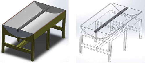
Figure 17. The orthographic and component drawings of the reheating unit.
Figure 18. The detailed support drawing of the reheating unit.
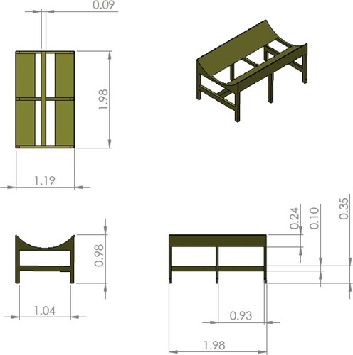
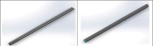
Figure 19. Sectional views of the air-solar-finned absorber.
4. Conclusions
The present work has formulated design equations (functions) and simulated the design functions to establish the optimum design variables upon which the performance yardstick were determined. The optimum performance yardsticks include; collector (0.44), optical (0.79) and thermal (0.31) efficiencies and an essential design variable, the exit fluid temperature (110°C) by adopting slight obtuse-angled rim design. These optimum results entrenched a good balance among the optical, thermal and collector efficiencies as their values were all significant, which guaranteed an appreciable exit fluid temperature above 100°C without inducing misalignment in the finned absorber. Moreover, the dependence of the collector, optical and thermal efficiencies on the design variables and parameters are clearly investigated with the revelation of inherent tradeoffs among the competing design variables, which further gave an overriding insight in setting appropriate design input data. Therefore, the objectives of the simulatory design were absolutely achieved and the current results equally synchronized well the practicable collector efficiencies (0.3649–0.5057) published in the literature (Mohamed, Citation2013 and Macedo-Valencia et al., Citation2014).
In the recent past, the premium design of the PTSC has been on the acute-angled rim design technique which is threatened by the misalignment problems, leading to a breakage of the glass envelope and the distortion of the performance yardsticks due to thermal accumulation in the absorber tube orchestrated by high thermal concentration.
Thus, the present work is advocating for the application of slight obtuse-angled rim design (≤94°) as the cutting-edge in developing PTSCs due to the enormous advantages of preserving the performance yardsticks from misalignment problems and equally shielding the absorber from the colossal thermal losses.
Moreover, low thermal efficiency should be avoided in the PTSC design as the exit fluid temperature is suppressed by a high optical concentration ratio associated with the extreme obtuse-angled rim design (EOARD). Besides, the fins are useful in checkmating the optical and thermal risks associated with the operation of PTSCs, a meticulous and optimum design of the PTSC variables; the optical distance and the height of the trough can be an addendum in eliminating the misalignment issues in the PTSC design and operation. Thus, the present work is advocating for the application of SOARD and a system approach in the design of thermal systems employed in the exploitation of solar resources (CitationStoecker 1989).
Cover Image
Source: Author.
Supplemental Material
Download PDF (892.5 KB)Acknowledgements
The authors wish to acknowledge Prof. W. F. Stoecker whose powerful resources in the “Design of Thermal Systems” are invaluable in the design of the reheating unit which a typical design of thermal system.
Disclosure statement
Authors unanimously declaring that there is no conflict of interest in this work.
Supplementary materials
The supplemental data for this article can be accessed here.
Additional information
Funding
Notes on contributors

S. N. Nnamchi
NNAMCHI, S. N. Nnamchi is a Senior Lecturer in the Department of Mechanical Engineering (ME) at Kampala International University (KIU), Uganda. Has made prolific research contribution in thermofluids, renewable and non-renewable energy systems; design, modelling and simulation.
O. A. Nnamchi
NNAMCHI, O. A. Nnamchi is a postgraduate student of Bio-processing and Food Engineering in the Department of Agricultural Engineering and Bio resources, Michael Okpara University, Nigeria. Her fast rising profile in Bioprocessing, Food and Chemical Engineering is valuable to this project.
M. O. Onuorah
ONUORAH, M. O. Onuorah is an Associate Professor of Applied Mathematics with the Physical Sciences Department, KIU with ample publications in Biological, Ecological and Dynamical systems modelling.
K. O. Nkurunziza
NKURUNZIZA, K. O.Nkurunziza is a postgraduate student of ME at KIU. He’s developing a solar reheating unit with a distinction in air-solar-finned absorber design.
S. A. Ismael
ISMAEL, S. A. Ismael is a dynamic postgraduate student of ME at KIU. He’s developing a solar preheating unit with excellence in air-solar-finned absorber design.
References
- Abadal, G., Alda, J., & Agustí, J. (2014). Electromagnetic radiation energy harvesting – The rectenna based approach. IntechOpen Open access peer-reviewed chapter. https://doi.org/10.5772/57118
- Abbood, M. H., & Mohammed, M. M. (2019). Experimental characteristic of a solar parabolic trough collector with indirect steam generation system. International Journal of Energy and Environment, 10(2), 87–30. https://www.researchgate.net/profile/Mohammed_Abood2/publication/332401162_INTERNATIONAL_JOURNAL_OF_ENERGY_AND_ENVIRONMENT_Experimental_characteristic_of_a_solar_parabolic_trough_collector_with_indirect_steam_generation_system/links/5cb1d901a6fdcc1d49916591/INTERNATIONAL-JOURNAL-OF-ENERGY-AND-ENVIRONMENT-Experimental-characteristic-of-a-solar-parabolic-trough-collector-with-indirect-steam-generation-system.pdf
- Abdelhady, S., Shaban, M., Fathy, M., & Ahmed, A. (2017). Design and testing parabolic trough solar collector. Journal of Scientific and Engineering Research, 4(1), 105–109. http://jsaer.com/download/vol-4-iss-1-2017/JSAER2017-04-01-105-109.pdf
- Alfelleg, M. A. A. (2014). Modeling and experimental investigation of parabolic trough solar collector. Dissertations and Theses, 11; Combustion Science, 30(3), 231–295. https://commons.erau.edu/edt/11
- Ali, M., & Sadek, S. (2018). Free convection heat transfer from different objects. Heat Transfer - Models, Methods and Applications, 1, 1-20. https://doi.org/10.5772/intechopen.75427
- Barone, G., Buonomano, A., Forzano, C., & Palombo, A. (2019). Solar thermal collectors. In Solar hydrogen production (pp. 151–178). Academic Press.
- Borah, A., Khayer, S. M., & Sethi, L. N. (2013). Development of a compound parabolic solar concentrator to increase solar intensity and duration of effective temperature. International Journal of Agriculture and Food Science Technology, 4(3), 161–168. https://www.ripublication.com/ijafst_spl/ijafstv4n3spl_01.pdf
- Cheng, K. C., & Fujii, T. (1998). Heat in history Isaac Newton and heat transfer. Heat Transfer Engineering, 19(4), 9–21. https://doi.org/10.1080/01457639808939932
- Dudley, V., Kolb, G., Sloan, M., & Kearney, D. (1994). SEGS LS2 solar collector-test results. Report of Sandia National Laboratories, SAN94-1884.
- Gaitan, D. J. (2012). Design, construction, and test of a miniature parabolic trough solar. https://digitalcommons.calpoly.edu/cgi/viewcontent.cgi?article=1034&context=bmedsp
- Ghodbane, M., & Boumeddane, B. (2018). Engineering design and optical investigation of a concentrating collector: Case study of a parabolic trough concentrator. Journal of Fundamental and Applied Sciences, 10(2), 148–171. doi: 10.4314/jfas.v10i2.11
- Goswami, D., & Kreith, F. (2008). Energy conversion (2nd ed). CRC Press, Taylor & Francis Group.
- Gwania, M., Abubakarb, G. A., Abbasc, M., Na Allahd, M., & Danyaroe, J. (2015). Design, fabrication and experimental study of solar parabolic dish concentrator for remote area application. International Journal of Sciences: Basic and Applied Research (IJSBAR), 23(1), 230–241. https://www.gssrr.org/index.php/JournalOfBasicAndApplied/article/view/4136
- Hammami, M., Torretti, S., Grimaccia, F., & Grandi, G. (2017). Thermal and performance analysis of a photovoltaic module with an integrated energy storage system. Applied Sciences, 2017(7), 1107. https://doi.org/10.3390/app7111107
- Huanga, W., Xu, Q., & Hu, P. (2016). Coupling 2D thermal and 3D optical model for performance prediction of a parabolic trough solar collector. Solar Energy, 139(2016), 365–380. https://doi.org/10.1016/j.solener.2016.09.034
- Izweik, H. T., Ahmed, M., Ahmed, A. M., & Albusefi, A. A. (2016). Design, construction, and experimental testing of a parabolic trough collector for process heat applications. International Journal of Innovative Research in Science, Engineering and Technology, 5(9), 15890–15894. http://www.ijirset.com/upload/2016/september/65_24_Design_FORIEGN.pdf
- Kalogirou, S. (2004). Solar thermal collectors and applications. Progress in Energy, 30(3), 231-295. https://doi.org/10.1016/j.pecs.2004.02.001
- Kalogirou, S. (2009). Thermal performance, economic and environmental life cycle analysis of thermosiphon solar water heaters. Solar Energy, 83(1), 39–48. https://doi.org/10.1016/j.solener.2008.06.005
- Kreith, F., Timmerhaus, K., Lior, N., Shaw, H., Shah, R. K., & Bell, K. J. (2000). The CRC handbook of thermal engineering ( Frank Kreith (Ed.)). CRC Press LLC.
- Kumar, A., Chand, S., & Umrao, O. P. (2013). International Journal of Engineering Research & Technology (IJERT), 2(6), 2771–2785. https://www.ijert.org/research/selection-and-evaluation-of-different-tracking-modes-performance-for-parabolic-trough-solar-collector-IJERTV2IS60757.pdf.
- Kuo, C. W., Yen, P. S., Chang, W. C., & Chang, K. C. (2014). The design and optical analysis of compound parabolic collector. Procedia Engineering, 79(2014), 258–262. https://doi.org/10.1016/j.proeng.2014.06.340
- Lovegrove, K., & Pye, J. (2012). Fundamental principles of concentrating solar power (CSP) systems. concentrating solar power technology (pp. 16–67). Woodhead Publishing Limited. https://doi.org/10.1533/9780857096173.1.16
- Macedo-Valencia, J., Ramírez-Ávilaa, J., Acostaa, R. O. A., & Aguilar, J. O. (2014). Design, construction and evaluation of parabolic trough collector as demonstrative prototype. Energy Procedia, 57(2014), 989–998. https://doi.org/10.1016/j.egypro.2014.10.082
- Mohamed, E. A. (2013). Design and testing of a solar parabolic concentrating collector. Renewable Energy and Power Quality Journal, 1(11), 72–76. https://doi.org/10.24084/repqj11.219
- Montes, M., Abánades, A., Martínez-Val, J., & Valdés, M. (2009). Solar multiple optimization for a solar-only thermal power plant, using oil as heat transfer fluid in the parabolic trough collectors. Solar Energy, 83(12), 2165–2176. https://doi.org/10.1016/j.solener.2009.08.010
- Montesa, I. E. P., Beniteza, A. M., Chaveza, O. M., & Herrera, A. E. L. (2013). Design and construction of a parabolic trough solar collector for process heat production. Energy Procedia, 57(2014), 2149–2158. https://doi.org/10.1016/j.egypro.2014.10.181
- Nnamchi, S. N., Nnamchi, O. A., Sangotayo, E. O., Ismail, S. A., Nkurunziza, O. K., & Gabriel, V. (2020). Design and simulation of air-solar preheating unit: An improved design of a flat plate solar collector. Journal of Energy and Environment, 11(2), 97-108. https://doi.org/10.5829/ijee.2020.11.02.02
- Oko, C. O. C. (2011). Introduction to heat transfer: An algorithmic approach. Pam Unique Publishing Company.
- Pavlović, S., Vasiljević, D., & Stefanović, V. (2014). Optical design of a solar parabolic thermal concentrator based on trapezoidal reflective petals. In Proceedings (pp. 1166–1171). https://pdfs.semanticscholar.org/0f9b/0396821dd7961215cc7444c231364ef6e073.pdf?_ga=2.86147806.734397879.1594395134-82926339.1585759371.
- Pierucci, G., Fontani, D., Sansoni, P., & Lucia, M. D. (2014). Shape optimization for parabolic troughs working in non-ideal conditions. Energy Procedia, 57(2014), 2231–2240. https://doi.org/10.1016/j.egypro.2014.10.230
- Ricardo, V. P. (2011). Simplified methodology for designing parabolic trough solar power plants [Graduate Theses and Dissertations]. USF Faculty Publications. http://scholarcommons.usf.edu/etd/3390
- Rincón-Casado, A., Sánchez de la Flor, F. J., Chacón Vera, E., & Sánchez Ramos, J. (2017). New natural convection heat transfer correlations in enclosures for building performance simulation. Engineering Applications of Computational Fluid Mechanics, 11(1), 340–356. https://doi.org/10.1080/19942060.2017.1300107
- Siqueira, A., Gomes, P. E. N., Gomes, G., Torrezani, L., & Geraldo, P. (2014). Heat transfer analysis and modeling of a parabolic trough solar collector: An analysis. Energy Procedia, 57(2014), 401–410. https://doi.org/10.1016/j.egypro.2014.10.193
- Stoecker, W. F. (1989). Design of thermal systems (3rd ed.). McGraw*Hill.
- Sup, B. A., Zainudin, M. F., Ali, T. Z. S., Bakar, R. A., & Ming, G. L. (2015). Effect of rim angle to the flux distribution diameter in solar parabolic dish collector. Energy Procedia, 68(2015), 45–52. https://doi.org/10.1016/j.egypro.2015.03.231
- Tijani, A. S., & Bin Roslan, A. M. S. (2014). Simulation analysis of thermal loss of parabolic trough solar collector in Malaysia using computational fluid dynamics. Procedia Technology, 15(2014), 841–848. https://doi.org/10.1016/j.protcy.2014.09.058
- Upadhyay, B. H., Amitkumar, J. P., & Ramana, P. V. (2019). A detailed review on solar parabolic trough collector. International Journal of Ambient Energy, 1–21. https://doi.org/10.1080/01430750.2019.1636869
- Vasquez, P. R. (2011). Simplified methodology for designing parabolic trough solar power plants. USF Press.