
 ?Mathematical formulae have been encoded as MathML and are displayed in this HTML version using MathJax in order to improve their display. Uncheck the box to turn MathJax off. This feature requires Javascript. Click on a formula to zoom.
Abstract
This paper considers the main parameters of the solar collector with thermosyphon circulation for the solar heat supply system. There was developed a flat solar collector construction with thermosyphon circulation wherein the heat transfer coefficient is increased by removing the additional partitions between a panel and heat insulation. The solar collector’s efficiency reached by the availability of a tank and thermal pump in the construction where a condenser and evaporator executed the form of a heat exchanger of «spiral in spiral» type and heat exchanger pipe connections are one above another, which allows increasing the square and heat exchange intensity. The outcome of the study is a description of the mathematical analysis of the heat transmission process in the tank accumulator. We have shown a heat carrier thermophysical parameter dependence on the temperature.
PUBLIC INTEREST STATEMENT
The paper considers the thermosyphon flat solar collector’s main parameters for the solar heat supply system. We propose an approach, a new construction of thermosyphon flat solar collector, in which the thermal transmission coefficient has been increased by removing the additional partitions between a panel and heat insulation. The efficiency of a solar collector is reached by a combination of the tank with heat exchanger and heat pump in which the condenser and the evaporator have the form of a heat exchanger of the type “spiral in a spiral”. Also, the thermal connection of heat exchanger tubes laid over each other, which allows increasing the area and intensity of heat transfer. We present the mathematical analysis of the heat transmission process in the tank accumulator with the initial and boundary conditions.
1. Introduction
Renewable energy sources have the potential to meet the current and future forecast global needs in the energy without influencing the environment. For sustainable satisfying the global energetic needs, the renewable power sources are solar energy, wind, hydroenergetics, biogas, and geothermal energy are potential candidates. The best alternative for meeting the growing need for energy is solar power. Solar radiation transformation into heat is one of the simplest and direct applications of the power thereof. In order to carry out the mathematical model analysis of the developed double-circuit solar plant with thermosyphon circulation, we considered several existing models.
The authors provided the prediction of the thermal performance of the cavity receiver in different amounts of solar irradiance, the cavity depth, and the diameter of tube by the artificial neural networks (ANN) methodology. The results of research that the ANN method can accurately predict the thermal performance of the cavity receiver at different variable parameters of the cavity depth, and tube diameter (Loni et al., Citation2017). In this study, the calculation of exergy efficiencies is presented for an alternative using energy for the thermophotovoltaic (TPV)-driven thermionic refrigerator (TIR) by solar energy (Açıkkalp et al., Citation2020). Authors reviewed solar thermal technology including soar trough collectors, linear Fresnel collectors, central tower systems, and solar parabolic dishes, and discussed their opportunities. Also, they showed that concentrated solar power plants are better in economic return based on economic considerations (Ahmadi et al., Citation2018). In the study, the authors considered the main disadvantage of using PV and solar flat collector systems are their more space occupation. They proposed to solve it by using the concentrated PV (CPV) systems that focus the received irradiation on a smaller surface (Khatibi et al., Citation2019). Gao et al. and Alvarez et al. presented the information about the solar collector’s parameter computation (Alvarez et al., Citation2010; Gao et al., Citation2007). Authors in the paper on the dynamic model spatial distribution did not consider the collector as a combined collector (Yedilkhan et al., Citation2018). The paper described a developed calculation technique and the choice of the geometrical parameters of the solar collector with the siphon effect (Y. Amirgaliyev et al., Citation2019). The paper considered the study of convective heat transfer in flat-plate solar collectors, the analysis of the heat transfer by circular and flat tubes upon conforming the forced and free convections, placed vertically or horizontally with various liquid flow directions. Nusselt dependencies are obtained in circular and flat pipes, which shows that corresponding equations allow defining the heat transfer intensity for all fluids with appropriate accuracy (Y. N. Amirgaliyev et al., Citation2018).
The paper studied the photoelectric system spatial distribution, tunnel drier, solar water heater. The authors strive to use the modeling approach to designing and constructing the solar collectors for the low and high temperatures at the inlet of the absorption solar drier for drying the agricultural products (Chow et al., Citation2006; Ji et al., Citation2009; Talbot et al., Citation2016; Tiwari & Sodha, Citation2007). Solar thermal energy is a renewable power source widely used all over the world. Such solar collectors are used widely starting from household solar water heaters (SWH) to complex solar farms for electric power generation. SWH proved reliability and economic viability for hot water production in the household and commercial sectors. The paper showed that the SWH principal components are the collectors’ flat plates or heating elements (Açıkkalp et al., Citation2020). In order to avoid the damages from freezing (boiling) and SWH indirect heating, there is a heat exchanger between the tanks or inside the tank. A reservoir placed either above the collector (thermosyphon system) or at the lower level (force circulation). The authors proposed to use the fin is to enlarge the surface area exposed to the sun’s heat so that radiation heat transfer increases. Based on the observations it showed that the efficiency of the collector is very dependent on the intensity of solar radiation and depends on the loss of radiation intensity for the flat-finned tetragon solar collector. (Wuryanti & Megawati, Citation2019). The authors presented the performance of teaching–learning-based optimization (TLBO) algorithm to obtain the optimum set of design and operating parameters for a smooth flat-plate solar air heater. The computational results have shown that the TLBO algorithm is better or competitive to other optimization algorithms (Venkata & Waghmare, Citation2015). The solar collector’s square constitutes about 120000 m2 (Lin et al., Citation2012). On an industrial scale, the electric energy provided with the systems for hot water production from 40 to 80°С (Karagiorgas et al., Citation2001). For workings in the water storage systems, the solar collectors are usually divided by means of the forced circulation system, installed at the desired temperature, which is fixed at collector’s outlet and secures maximum performance and saving (Sheremet, Citation2010). The mathematical model includes the very differential conservation laws of impulse and energy. Actual outcomes of the physical process and mathematical modeling of the heat transmission process by reservoir wall heat conductivity might lead to certain values for computing the flat-plate collector with thermosyphon circulation (Jiao et al., Citation2008). There has been presented a multidimensional mathematical model of influencing the working body filling-in coefficient in the stationary mode of water heating in the thermosyphon. As a result, the researchers have developed the thermosyphon solar collector mathematical modeling based on the equations for laminar flows of compressible perfect gas (Harley & Faghri, Citation1994).
In the paper, we validated the thermosyphon effect of principal parameters. The equation system of the heat transfer in the copper tube coil, absorbing the heat from the solar beam energy transformer into the thermal power is solved. The equation of the transfer heat in the tank accumulator together with the initial conditions is presented. The dependencies of the heat carrier thermal physical parameters on the temperature are presented. The equation of the heat carrier motion along the collector circuit under the thermosyphon effect influence is solved.
2. Method of research
Flat-plate solar collectors with thermosyphon circulation used for transforming the falling solar radiation into thermal power. The power accumulated in the tank for fluid storage and used, as needed for premises and water heating. shows a double-circuit solar installation with thermosyphon circulation.
Figure 1. Principal schema of a double-circuit solar plant with thermosyphon circulation
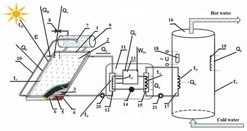
The operation of the plant being offered is fulfilled as follows. The solar energy E with the temperature t0 is absorbed by the solar collector 1, with the temperature t1, heating the solar energy, passes through translucent insulation sealed double glazed unit 2. The heat, obtained from the solar flow, heats the fluid in the coils 3, which is removed from the collector, and instead of it there inlets cold water from the pipeline with a valve for the cold water 8, and in the tank dozer syphon 7 there takes place constant the thermosyphon circulation by means of circulation pipe 10. Further, the fluid goes to a thermal pump 11, which consists of a condenser’s evaporator 12 with the temperature t2, in which a heat exchanger has been made in the coil form, absorbing the transfer medium heat, decreases its temperature lower than the atmospheric temperature (Q2) with the help of speed control valve 14, thereby facilitating the additional heat absorption from the atmospheric air. The diagram also demonstrates the solar radiation, reflected from the semitransparent coating (Q0) and an absorbing panel surface (Q1). In the thermal pump there executed a transfer of heat carrier power with relatively low temperature to the heat exchanger heat carrier of the condenser15 in the spiral form with higher temperature t2, which increases the square, as well, the heat exchanger intensity. To fulfill the cycle thereof there is used a compressor 13 with the temperature t3, with an electric driver 17. Further, by means of the condenser’s heat exchanger 15 with the temperature t4, the heat from a thermal pump (Q5) is transferred to the heat exchanger’s tank-accumulator Q6 with the temperature t6 of the heating system 18. As the plant has two circuits, it has automatic circulation pumps 19 and 20 for the fluid circulation between the solar collector and evaporator, condenser, and tank accumulator. Water temperature is adjusted to the required technological level and supplied to a consumer for hot water supply and heating aims.
shows a model of a flat solar collector. The essence and novelty are that, unlike the well-known design principle, the collector contains a transparent double-glazed window 2 with double glass and with reduced pressure, as well as a perimeter frame 1. The bottom of the wooden frame 7 is made of plywood 8 mm thick, and heat-insulating film 5 with foil is glued to them. In the gap formed between the double-glazed window and the bottom of the frame, a flexible thin-walled stainless corrugated tube 4–16 mm is laid in the form of a coil. The ends of the tube are attached to the inlet and outlet protruding pipes 6.
Figure 2. Flat solar collector
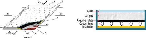
The paper considers the mathematical models of separate constructions and functioning modes of the double-circuit solar collector with thermosyphon circulation. We have considered developed by us a new construction flat solar collector with thermosyphon circulation, in which the heat transmission factor has been increased at the expense of removing the additional partitions between a panel and heat insulation. The considered solar collector performance achieved due to availability of a tank dozer and thermal pump in the design, where a condenser and evaporator have in the form of a heat exchanger of «spiral in spiral» type, and heat exchanger pipelines placed one above another, allowing increasing the square and heat exchange intensity. An outcome of this research is a theoretical and mathematical analysis of non-stationary thermal regime of flat-plate solar collectors in the functioning modes being considered. Based on the analysis results, we can optimize the design individual elements, as well as forecast the thermal mode and select the alternative solutions on the flat solar collectors’ design and operation regimes.
The core problem of the solar heat supply thermosyphon system is the height at which the solar energy tank accumulator shall be placed for maximum solar collector operation performance. 300 mm above the collector’s upper part there shall be positioned the tank-accumulator’s bottom. The water through the pipe enters the tank-accumulator’s upper part, goes up along the collector upon heating, expands in the collector, and becomes less dense. As a result, cooler water at the tank bottom displaced and flows to the collector’s lower part along another pipe. That water, in its turn, is heated and runs up into the tank. While the solar energy enters, the water will constantly circulate along that circuit, heating it. As the tank is raised over the collector, the effect of the circulation flipping in the result of the heat carrier night cooling in the collector comes to none, as cold water simply masses up in the system’s low point (on collector’s bottom), whereas warm water remains in the tank.
The main optimal parameter values for flat solar collectors, we defined the annual specific heat capacity:
where —average annual total solar radiation on a horizontal surface,
;
—parameters determined from EquationEquations (2)
(2)
(2) and (Equation3
(3)
(3) ).
where r—characteristic of the thermal insulation properties, it is the ratio of the daily heating load at an outdoor temperature equal to 0°C to the daily load of hot water supply.
—the replacement coefficient, approximately taken from 0.2 to 0.4.
;
—calculated coefficients are in .
Table 1. Technical specifications of flat-plate solar collector
Table 2. Values of coefficients for a flat solar collector
For different values of the replacement coefficient , the specific annual heat output
should be increased (decreased) in accordance with the data in .
Table 3. Values of coefficients for a flat solar collector
Table 4. Value of coefficients and
Table 5. Value of coefficients and
where is the specific annual heating capacity for values
other than 0.5.
—change in annual specific heat capacity, %.
Our approach of improvement, a solar hot system is that the thermal insulation material is a heat-insulating transparent double-glazed window with reduced pressure, and the heat carrier is made of a stainless thin-walled corrugated tube. Heat received from solar flux heats the liquid in the coils, which is removed from the collector. Its place comes the cold liquid from the tank to the dosing and there is a constant circulation, which increases the efficiency of heat transfer, by avoiding additional intermediate walls between the slab and the insulation, which simplifies the design of collectors, easy to use, heats up quickly, and given the hour the air temperature in summer and wintertime.
3. Results
When the water heated and its density decreased in the collector’s contour, a hydrostatic pressure P (Pa) has been the excess.
where g—gravity acceleration, m/s2; F—vertical interval between the solar collector and tank-accumulator centers, m; db—tank-accumulator height, m; dc—collector’s length, m; dc-b—distance between the tank-accumulator bottom and collector’s upper part, m.
The pressure balanced by the head loss, caused by the total hydraulic resistance of the collector’s contour, consisting of resistances of copper tubular collector’s spiral, incoming and coming from the pipeline’s heat carrier and devices of their connecting with a collector and tank accumulator. During calculating the loss pressure in the hydraulic contour split into the linear and non-linear areas. Each element of the copper spiral consists of a linear part and two non-linear parts.
The overall amount of the spiral elements computed according to the formula:
where is the distance from the collector’s edges to the linear part of the upper and lower spiral elements, m;
is the distance from the collector’s right and left sides to the copper spiral elements, m. Considering that the number of the spiral elements, in compliance with constructive features of the collector shall be an even integer, the value
is rounded off to the nearest even number.
The distance between the spiral elements is defined from the equation:
The length of the arc of the non-linear (, m) and linear (
, m) copper spiral element parts
Pressure loss in the spiral element’s linear part is described with the equation [24]:
where µ is an average length spiral linear part’s dynamic transfer medium viscosity, H·c/m2; —transfer medium average speed, m/s.
Pressure drop in the collector’s spiral element non-linear part is computed from the expression (B. Carnot formula (Poirier, Citation2014)):
where —local resistance coefficient. Collector’s spiral non-linear part’s local resistance represents the pipeline rotation for 90о and it is computed according to the formula:
where R is the radius of the spiral copper tube rotation, m, R = se/2.
For simulating the hydraulic resistance drop in the tubular spirals at the collector’s modules there were obtained results on the equation ground:
at the first collector’s area:
at i-collector’s area, i = 2, …, nк—1:
Heat amount , incoming from the collector into a tank accumulator we will define using the formula
Figure 3. Pressure drop in flat solar collector element’s linear part
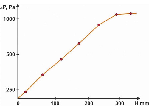
presents the pressure drop in flat solar collector element’s linear part. The pressure drop is the main factor in thermosyphon system performance. Thus, we studied a prediction of the pressure drop in the flat-plate solar collector. Different dimensions of collectors used for tests, the model verified and got errors within the range of 3–8% by normalized mean square deviation. In the case of flat-plate solar collectors, which will be used in water supply thermosyphon systems, the model could be used for comparison solutions between production and thermosyphon characteristics.
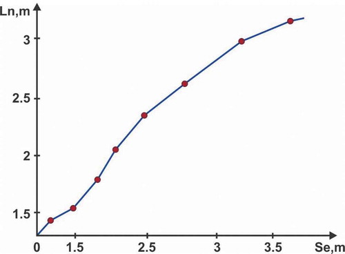
Figure 4. Total amount of the flat solar collector’s copper spiral elements
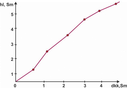
presents the total amount of the flat-plate solar collector copper spiral’s elements. From , the more the number of copper spiral elements, the bigger the distance from the collector’s edges to the linear part of spiral upper and lower elements.
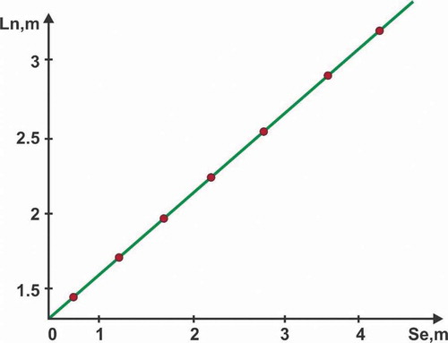
Figure 5. Distance between flat-plate solar collector copper spiral elements
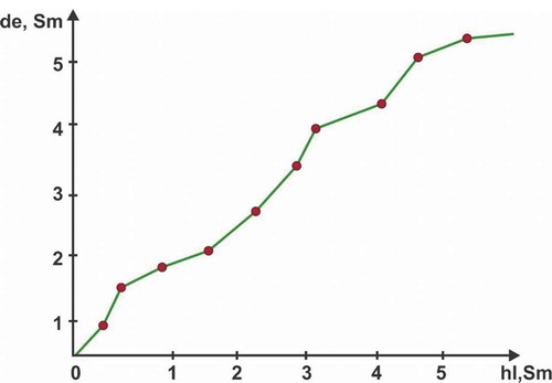
Figure 6. Length of the arc of flat solar collector copper spiral non-linear part element
presents the length of the arc of flat solar collector copper spiral non-linear part element. The bigger the copper spiral radius and diameter, the bigger amount of fluid will flow under normal pressure. As well, it can be asserted, the bigger the copper spiral’s stroke the less amount of fluid will flow along the tube. It proved that all parameters computed by means of experimental data are governed by physics laws, in particular, mechanics of flows.
Figure 7. Length of the arc of flat solar collector copper spiral linear part element
shows the length of the arc of the flat solar collector copper spiral linear part element. The thermal performance decreased almost linearly upon increasing the distance between the tubes. It means that the tube’s high density per square unit (or length) of the absorbing plate increases its thermal efficiency.
Figure 8. Amount of heat qк(J), entering a tank accumulator from the collector
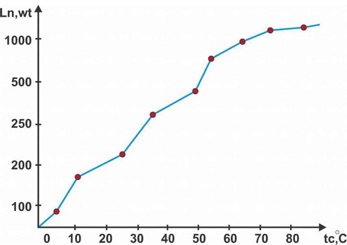
presents the dependence of heat amount qк(J), entering a tankaccumulator from the collector, on the water heating temperature. From , the outcomes show, that daily effective heat gain has constituted about 1050 MJ under different atmospheric air conditions. Under temperature conditions thereof, the maximum value of the system’s daily average performance has amounted to 52% with a bit difference between collectors and outside temperatures. While in other days, the system’s daily average performance is almost 50%. The initial temperature in the tank exercises a significant influence on the system’s daily effectiveness. The increase of difference between water temperature and collector’s temperature will raise the heat gain from the collectors. In comparison to other days, the system’s daily performance might reach 60% at 7°С initial temperature.
4. Conclusion
The equation system for heat transmission in the solar collector’s design elements is solved. Collectors’ different dimensions used as a test case, wherein the mockup checked within the range of 3–8% with relation to normalized mean square deviation. Thermal performance decreases almost linearly along with increasing the distance between the tubes. It stresses the complexity of heat transfer to the tube from relatively big distances. This points to the fact that the tube’s higher density per square unit (or length) of the absorbing plate increases its thermal effectiveness. The arched profile is for 24–27% more effective than a rectangular profile. Mass flow increase of the water, circulating through the collector’s tubes, will promote larger heat exchange, which will positively influence the system’s effectiveness. As a result of experiments, the daily effective heat gain has constituted about 1050 МJ at various environment air. Under temperature conditions, the system’s daily effectiveness maximum value has amounted to 52% with a bit difference between collectors and environmental temperatures.
Acknowledgements
This work is supported by a grant from the Ministry of Education and Science of the Republic of Kazakhstan within the framework of the Project «BR05236693 Mathematical and computer models, hardware and software tools, and experimental development on the creation of network combined effective dual-circuit solar collectors with thermosiphon circulation and monitoring of their functioning».
Additional information
Funding
Notes on contributors
Amirgaliyev Yedilkhan
Amirgaliyev Yedilkhan, Doctor of Technical Sciences, Professor, the Corresponding Member of the National Academy of the Republic of Kazakhstan. From 2010 to the present, he is a Head of the Laboratory of Artificial Intelligence and Robotics at the Institute of Information and Computational Technologies of the Ministry of Education and Science RK, the head of several research projects financed by the grants of the MES of the RK. Amirgaliyev Y. is a professor of universities - Al-Farabi Kazakh National University, IITU, SDU.
Kozbakova Ainur
Professor Y. Amirgaliyev’s research topics focus on problems in the field of image recognition, image analysis and processing, robotics with machine vision and the development of intelligent systems, as well digitalization of technological processes and objects used in the green energy industry.
Fifteen PhD theses were defended under the guidance of professor Y. Amirgalyiev and resulted in practical implementation in scientific and production processes. He has published over 300 research papers, including over 70 papers in the Scopus and WoS databases, H=10.
References
- Açıkkalp, E., Yerel Kandemir, S., & Ahmadi, M. H. (2020). Performance evaluation of the thermophotovoltaic-driven thermoionic refrigerator. Journal of Energy Resources Technology, 142(3). https://doi.org/10.1115/1.4044558
- Ahmadi, M. H., Ghazvini, M., Sadeghzadeh, M., Alhuyi Nazari, M., Kumar, R., Naeimi, A., & Ming, T. (2018). Solar power technology for electricity generation: A critical review. Energy Science & Engineering, 6(5), 340–13. https://doi.org/10.1002/ese3.239
- Alvarez, A., Cebaza, O., Muñiz, M. C., & Varela, L. M. (2010). Experimental and numerical investigation of a flat-plate solar collector. Energy, 35(9), 3707–3716. https://doi.org/10.1016/j.energy.2010.05.016
- Amirgaliyev, Y., Kunelbayev, M., Amirgaliyev, B., Kalizhanova, A., Auelbekov, O., Katayev, N., & Kozbakova, A. (2019). Study of Convective Heat Transfer in Flat Plate Solar Collectors. Journal WSEAS Transactions on Systems and Control, 14, 129–137. 1991-8763E-2224-2856. https://www.wseas.org/multimedia/journals/control/2019/a325103-823.php
- Amirgaliyev, Y. N., Kunelbayev, M., Kalizhanova, A. U., Wójcik, W., Amirgaliyev, B., Auelbekov, O., Kataev, N. S., & Kozbakova, A. K. (2018). Calculation and selection of flat-plate solar collector geometric parameters with thermosiphon circulation. Journal of Ecological Engineering, 19(6), 176–181. https://doi.org/10.12911/22998993/91882
- Chow, T. T., He, W., & Ji, J. (2006). Hybrid photovoltaic thermosyphon water heating system for residential application. Solar Energy, 80(3), 298–306. https://doi.org/10.1016/j.solener.2005.02.003
- Gao, W., Lin, W., Liu, T., & Xia, C. (2007). Analytical and experimental studies on the thermal performance of cross-corrugated and flat plate solar air heaters. Applied Energy, 84(4), 425–441. https://doi.org/10.1016/j.apenergy.2006.02.005
- Harley, C., & Faghri, A. (1994). A complete transient two-dimensional analysis of two-phase closed thermosyphons including the falling condensate film. Journal of Heat Transfer, 116(2), 418–426. https://doi.org/10.1115/1.2911414
- Ji, J., He, H., Chow, T., Pei, G., He, W., & Liu, K. (2009). Distributed dynamic modelling and experimental study of PV evaporator in a PV/T solar-assisted heat pump. International Journal of Heat and Mass Transfer, 52(5–6), 1365–1373. https://doi.org/10.1016/j.ijheatmasstransfer.2008.08.017
- Jiao, B., Qiu, L. M., Zhang, X. B., & Zhang, Y. (2008). Investigation on the effect of filling ratio on the steady-state heat transfer performance of a vertical two-phase closed thermosyphon. Applied Thermal Engineering, 28(11–12), 1417–1426. https://doi.org/10.1016/j.applthermaleng.2007.09.009
- Karagiorgas, M., Botzios, A., & Tsoutsos, T. (2001). Industrial solar thermal applications in Greece economic evaluation, quality requirements and case studies. Renewable and Sustainable Energy Reviews, 5, 157–173.
- Khatibi, A., Razi Astaraei, F., & Ahmadi, M. H. (2019). Generation and combination of the solar cells: A current model review. Energy Science & Engineering, 7(2), 305–322. https://doi.org/10.1002/ese3.292
- Lin, W. M., Chang, K. C., Liu, Y. M., & Chung, K. M. (2012). Field surveys of non-residential solar water heating systems in Taiwan. Energies, 5(2), 258–269. https://doi.org/10.3390/en5020258
- Loni, R., Kasaeian, A., Shahverdi, K., Asli-Ardeh, E. A., Ghobadian, B., & Ahmadi, M. H. (2017). ANN model to predict the performance of parabolic dish collector with tubular cavity receiver. Mechanics & Industry, 18(4), 408. https://doi.org/10.1051/meca/2017016
- Poirier, B. (2014). A conceptual guide to thermodynamics. John Wiley & Sons.
- Sheremet, M. A. (2010). The influence of cross effects on the characteristics of heat and mass transfer in the conditions of conjugate natural convection. Journal of Engineering Thermophysics, 19(3), 119–127. https://doi.org/10.1134/S1810232810030021
- Talbot, P., Lhote, M., Heilporn, C., Schubert, A., Willaert, F.-X., & Haut, B. (2016). Ventilated tunnel solar dryers for small-scale farmers communities: Theoretical and practical aspects. Drying Technology, 34(10), 1162–1174. https://doi.org/10.1080/07373937.2015.1121395
- Tiwari, A., & Sodha, M. S. (2007). Parametric study of various configurations of hybrid PV/thermal air collectors: Experimental validation of theoretical model. Solar Energy Materials and Solar Cells, 91(1), 17–28. https://doi.org/10.1016/j.solmat.2006.06.061
- Venkata, R. R., & Waghmare, G. (2015). Optimization of thermal performance of a smooth flat-plate solar air heater using teaching–learning-based optimization algorithm. Cogent Engineering, 2(1), 997421.
- Wuryanti, S., & Megawati. (2019). Fin flat-plate type tetragon solar collector design based on convection radiation mechanism. Cogent Engineering, 6(1), 1637165. https://doi.org/10.1080/23311916.2019.1637165
- Yedilkhan, A., Merembayev, T., & Kunelbayev, M. (2018). Dynamic simulation of a solar hot water heating system for Kazakhstan climate conditions. In 2018 14th international conference on electronics computer and computation (pp. 206–212). IEEE.