 ?Mathematical formulae have been encoded as MathML and are displayed in this HTML version using MathJax in order to improve their display. Uncheck the box to turn MathJax off. This feature requires Javascript. Click on a formula to zoom.
Abstract
The purpose of this work is to understand the theoretical aspects related to the compact multi-domain (Optical, Electrical and Thermal) modeling of light-emitting diodes (LEDs). Prior studies have already deliberated extensively on modeling LEDs in multiple domains with diverse levels of intricacies. The need for standardized compact multi-domain models of light-emitting diodes is emphasized. The multi-domain theory explained in this work enables potential end-users to create their own compact multi-domain models of LEDs and study their working in different operating conditions. The end-users can create their own compact multi-domain models of LEDs either from experimental data or from electronic-datasheets. The procedure for developing mathematical models of LEDs in multiple domains is demonstrated in this work. The reason behind current control of LEDs is explained using multi-domain modeling theory. In what way the problem of thermal runaway is handled by driving LEDs with constant current is discussed using the concepts of multi-domain theory. Unlike prior models, it is proposed to model forward voltage as a junction temperature controlled voltage source. Optical power and heating power are represented as junction temperature controlled current sources. The importance of thermal metrics in assessing aging and performance levels is also discussed. This work also recommends minimum parameters required for developing multi-domain compact models of LEDs.
PUBLIC INTEREST STATEMENT
This work deliberates on mathematically representing the multi-domain operation of light-emitting diodes (LEDs). The purpose of this article is to discuss a method to synthesize optical, electrical and thermal characteristics of LEDs into a compact multi-domain model. The potential end-users use these models for studying LED operations in different operating conditions. Potential end-users can be LED lighting engineers, thermal engineers, electrical engineers, LED luminaire designers and optical engineers. The work described in this article is helpful in carrying out benchmarking studies from lab measurements and technical details obtained from manufacturers. Modeling methodology discussed in this work enables early market entry of reliable and economical LED lighting products. This work combines the offerings of industry, academia and software developers in bringing out industry ready LED models. Manufacturers provide LED portfolio for different applications. Academicians provide knowledge on compact modeling, model extraction and measurement methods. Software developers provide tools for simulation.
1. Introduction
A large number of new products are released into the market for different illumination applications. Not all of these new products live upto their potential of energy-saving, quite a few underperforming products are also appearing in the market. Poor products can discourage early adopters of this innovative technology, thereby significantly delaying market penetration of new products, and may thus disadvantage the entire SSL industry. To encourage top quality products, governments need to come up with guidelines for manufacturers to report product performance, whether it is in product labeling or data sheets. Energy departments across the world recommend that a minimum set of key parameters be reported by SSL manufacturers to accurately reflect their LED product performance (Baran et al., Citation2020; Reporting LED luminaire product performance, Citation2008). There exists contemporary work on modeling LEDs in multiple domains (Alexeev et al., Citation2019; Górecki & Ptak, Citation2021, Citation2020; Janicki et al., Citation2020; Pohl et al., Citation2020), however, the approach followed in this work is simple and easily understood.
1.1. Solid-state lighting performance parameters
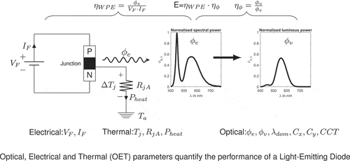
LEDs are semiconductor diodes with pn junction, as seen in , on application of forward bias voltage , forward current
flows, as a result, radiative electron-hole recombination occurs at the junction resulting in the emission of electromagnetic radiation in the form of radiant flux
from the junction. Not all the electrical power
is converted into electromagnetic radiation, a major portion of electron-hole recombination is non-radiative and needs to be dissipated away from the junction in the form of heat, represented as
and depends on the LED material efficiency in converting applied electrical power into light
or optical power
. Wall-plug efficiency or radiant efficiency is the energy conversion metric with which the LEDs or LED products convert electrical power into radiant flux. It is defined as the ratio of the radiant flux to the input electrical power and represented by
.
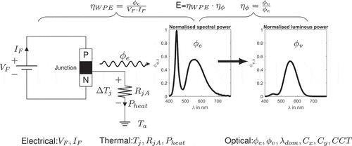
Figure 1. Optical, Electrical and Thermal (OET) parameters are used to quantify the performance of a LED
Efficient dissipation of waste heat from the junction is limited by
, thermal resistance along the heat conduction path from the junction-to-ambient. Improper dissipation of waste heat results in increase of junction temperature
, junction temperature build-up beyond the safety limits specified by the manufacturer will limit the useful life of the LED (Tsai et al., Citation2007). White LEDs used for general illumination applications, emit electromagnetic radiation along a wide spectral band, known as spectral power distribution (SPD), it is a representation of the radiant power
as a function of wavelength. Luminous flux
is a measure of the perceived power of radiant flux
.
Luminous efficacy of radiation is a measure of how well an LED produces perceivable light. It is the ratio of luminous flux
to radiant power
, measured in terms of lumen per watt. The spectral power distribution
is weighted with photopic sensitivity curve V(
) of the human eye to obtain luminous flux as seen in . The most widely used approach to create white LEDs used for general illumination applications is to use a blue LED chip combined with the phosphor. The phosphor layer converts a portion of the blue light and emits light at longer wavelengths. The amount of phosphor concentration defines how much of the blue light is converted (LED basics, Citation2010).
The most important set of performance parameters to be reported by luminaire manufacturers to accurately reflect performance of their LED products are luminaire efficacy (
), luminous flux
, input power
, power factor and correlated color temperature CCT. Some subset of these key parameters, in a simplified form, may also be suitable for the retail market like dominant wavelength
and chromaticity coordinates
,
both derived from spectral power distribution.
In addition to these basic OET parameters, rated lumen maintenance life of the luminaire, which is the elapsed operating time over which the luminaire will maintain the certain percentage of its initial lumen output is used to rate the performance of the luminaire. As typical lifetime of a LED luminaire is long, it is time-consuming to measure lumen depreciation over lifetime, and also it is impossible to validate lumen maintenance claims, hence it is recommended to measure instantaneous luminous flux and compare it with initial value; magnitude of deviation of this value from a predefined threshold at any given time interval can be used to rate the performance of luminaire.
A simple exponential relationship for lumen maintenance is expressed in Equationequation (1)(1)
(1) ,
where is the luminous flux at any time “t”,
is the initial luminous flux,
is the degradation constant.
For a given rated lumen maintenance lifetime L70, is estimated by substituting L70 for “t” in Equationequation (2)
(2)
(2) . Using the value of
, the corresponding luminous flux during any time interval is estimated and compared with the measured luminous flux in that instance. If the measured luminous flux is more than estimated one than the luminaire is operating as per its rated lumen maintenance life otherwise it can be inferred that the luminaire is under performing. Lumen maintenance is one of the performance criteria for LED products.
1.2. Thermal management key for solid-state lighting performance
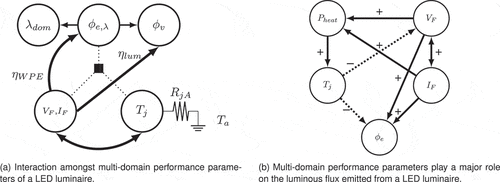
The optical, electrical and thermal characteristics of an LED luminaire exhibit a strong interdependency among each other as seen in . Only a part of electrical energy consumed by an LED is converted to light , while the rest is emitted as heat
. Inadequate dissipation of this waste heat will overheat the LED junction resulting in either catastrophic failure or lumen depreciation. Elevated junction temperature is responsible for change in color characteristics by affecting the dominant wavelength (
) and chromaticity coordinates (
,
) and also significantly affects its useful life (Elger et al., Citation2016; Jayawardena, Citation2013; D. Liu et al., Citation2014; Pecht et al., Citation2014; Zhou et al., Citation2016). Good thermal management is an important aspect of LED luminaire design as seen in . Electrical parameters forward voltage
and forward current
are dependent on junction temperature, thereby junction temperature affects LED efficiency in converting electrical power into visible light, as well as affecting light and color characteristics which are dependent on the LED material and its structure.
Figure 2. Mutual dependency of optical, electrical and thermal parameters of a LED luminaire represented in the form of cause and effect representation
The temperature differential between the junction and the ambient is a product of waste heat and thermal resistance along the heat conduction path from the junction-to-ambient. By reducing either
or
junction temperature can be controlled or lowered.
An LED luminaire designer or user wants to check if junction temperature or any reference temperature like one at the heat-sink stays within prescribed limits, or, alternatively, needs a temperature value for lifetime prediction. The most widely accepted and used expression is given in Equationequation (3)
(3)
(3) . Most of the cases
is provided by the manufacturer,
is supplied by the LED luminaire designers and
is a reference temperature that depends on the definition: either it some specified ambient temperature
, or a point on the package or board in question. The reference temperature can also be specified with respect to heat-sink as shown in Equationequation (4)
(4)
(4) , where the thermal resistance
is from the junction to heat-sink. After
is calculated using Equationequation (3)
(3)
(3) or (4), it is compared with a maximum temperature limit specified by the manufacturer, if
exceeds the limits specified by the manufacturer, luminaire will be likely redesigned with all consequences of time-to-market. There should be certainty about the accuracy of the calculated
before jumping to these kinds of decisions.
Junction temperature and junction-to-reference thermal resistance serve different purposes for both luminaire designers and device manufacturers. The goal of luminaire designers is to achieve better thermal performance of the luminaire and to establish figure-of-merit values for comparison with competitor products. Typically values are used for such purposes, these values help luminaire designers to study what-if scenarios and accurately predict
using which other important properties of LED luminaires can also be predicted. Since an LED luminaire is complex in its operation as seen in , standardized multi-domain models would be needed to comprehend operation of any LED luminaire, outlines of one such model are discussed in this work.
2. Need for standardized compact multi-domain models of light-emitting diodes
There is a need for industry accepted tools and standards to enable the design and production of cost effective, reliable and market-leading SSL products. Current, LED data-sheets report a single figure of merit: the thermal resistance , from junction to a reference point along the heat conduction path. This figure of merit is usually stated for one vague operating condition and does not sufficiently address the mutually dependent relations among optical, electrical, and thermal performance requirements (Martin et al., Citation2016). Effective SSL product design requires more detailing than is currently available in existing LED data-sheets. A complete mathematical model of LEDs that includes optical, electrical and thermal performance characteristics is required to understand the operation of each LED used at luminaire levels. This will allow LED luminaire designers to account for the effects of other LEDs and electronic components used in the design.
The adoption of SSL technology has transformed the lighting market, the illumination industry is becoming more competitive and attracting global players from industries other than LEDs, such as sensors, controls and integrated circuits. With LEDs there is no need for frequent replacements of luminaires, as a result, replacement market is seeing a natural decline and is projected to cause the total light source market to stabilize after couple of years (Lighting the way: Perspectives on the global lighting market, Citation2012). Decline in replacement market will accelerate the focus from light sources towards luminaires which includes drivers and controls. With the integrated penetration of LEDs and lighting controls, distribution channel structure of the market environment will be impacted. It is therefore important to respond to this market transformation by combining lighting knowledge base with new paradigms and corresponding solutions to the product design and development process. One of the important objectives is to streamline the early SSL product development phase by standardizing Compact LED models for design and performance assessment.
There exists need for standardized compact multi-domain models of LEDs, which need to be implemented by integrating models of other electronic and mechanical components to establish a more unified software-based design for complete LED luminaires as well as their performance analysis. The method suggested by Delphi4LED is to model the multi-domain characteristics of the LEDs such that it can be used at module and system levels (Bornoff et al., Citation2016; Janicki et al., Citation2019; Poppe et al., Citation2019). When an accurate thermal model of an LED is used conforming to the actual application environment, performance can be accurately analyzed. At most LED lighting companies, optical, electrical and thermal measurements are typically treated in an isolated manner because different testing teams and labs have not been adjusted to the changing landscape of the SSL industry. Though an integrated thermal and radiometric/photometric testing approach does exist for LEDs, it is still primarily used only in the traditional manner by LED thermal testing teams.
Standardized multi-domain testing protocols create a communication bridge between the LED and the luminaire manufacturers to improve the quality of lighting design implementation. The main aim in this respect is to establish a standardized method to create multi-domain LED compact models from test data and address the following key objectives (Martin et al., Citation2016):
• Define a set of LED model equations that can be implemented into a software, for the purpose of self-consistent multi-domain analysis of an LED’s OET characteristics.
• Integrate measurement data and modeling tools to demonstrate the benefits of compact models in performance assessment and in reducing development time and cost.
3. Electro-thermal characteristics of light-emitting diodes
LEDs are modeled using Shockley diode equation or the diode law, as shown in (5), it relates the forward current, forward voltage and junction temperature (Bogart et al., Citation2009; Boylestad & Nashelsky, Citation2012; Halkias et al., Citation2012; Hurtig et al., Citation1957):
where is the diode forward current,
is the diode saturation current, q is the electronic charge,
is the Boltzmann’s constant, and
is junction temperature in
. Under forward bias condition most LED junctions follow Equationequation (5)
(5)
(5) over a wide range of currents. In this discussion we shall limit our consideration of temperature dependence to the range in which Equationequation (5)
(5)
(5) is valid.
Under forward bias conditions at room temperature (25C) exponential term in Equationequation (5)
(5)
(5) , will be
, hence Equationequation (5)
(5)
(5) is rewritten as Equationequation (6)
(6)
(6) ,
Further diode saturation current has temperature dependence given by Equationequation (7)
(7)
(7) (Xi et al., Citation2005; Yao et al., Citation2016; York, Citation2010),
where is bandgap energy.
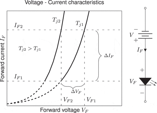
The electro-thermal characteristics of a typical illumination-grade LED are expressed in Equationequations (5)(5)
(5) and (Equation6
(6)
(6) ) and shown in . As seen in this figure, a slight change in forward voltage
results in a very large change in forward current
, under isothermal conditions. Also seen from , with the increase in junction temperature V–I characteristics shifts as a result of reduced forward voltage and also for the same forward voltage, forward current increases with increase in junction temperature. The solid lines in , represent normal operating parameters; the dotted lines are extrapolated ones. Further luminous flux
of an LED is proportional to its forward current, hence increased current levels will create unacceptable changes in photometric characteristics (Dulout et al., Citation2016; Gao et al., Citation2015; Grodzki, Citation2013; Keppens et al., Citation2009; Li et al., Citation2015; Moolman et al., Citation2009; Yuzhen et al., Citation2016). If the resulting forward current exceeds safe operating limits recommended by the manufacturer, the life and long-term performance of the LED will be affected.
Figure 3. Exponential nature of -
characteristics, a small change in forward voltage
creates a large change in forward current
3.0.1. Constant-current biasing
Under constant-current biasing, the forward voltage has a linear relationship with junction temperature, this can expressed by rearranging Equationequation (6)(6)
(6) as Equationequation (8)
(8)
(8) ,
Differentiating Equationequation (8)(8)
(8) , we get Equationequation (9)
(9)
(9) , which gives the temperature coefficient of forward voltage
.
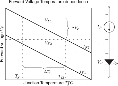
Temperature coefficient of forward voltage relates the rate of change forward voltage
to the corresponding change in junction temperature
at a given forward current
. In , corresponding to a constant current of
, the change in forward voltage
corresponds to junction temperature change of
.
3.0.2. Constant-voltage biasing
Temperature coefficient of forward current depends exponentially on forward voltage and also has a strong nonlinear dependence on junction temperature. As seen in , corresponding to constant forward voltage there is exponential rise in forward current with the increase in junction temperature. The temperature coefficient of forward current
is obtained by differentiating Equationequation (6)
(6)
(6) , and is expressed as in Equationequation (10)
(10)
(10) .
4. Thermal runaway problem
Electrical power applied to an LED is the product of forward current and voltage and is given by Equationequation (11)(11)
(11) ,
LEDs have a positive temperature coefficient (PTC) with respect to current as seen in Equationequation (10)(10)
(10) . As an LED is powered, power dissipated
at the junction increases its temperature, as a result LED forward voltage
decreases, causing the LED to draw more current as junction temperature increases. This situation is illustrated in , if the current is not limited, junction temperature increases drawing more current, which heats it up more, causing increased current, potentially leading to a situation known as Thermal runaway, a condition leading to the destruction of the LED (Arnold, Citation2004; Fan et al., Citation2011; Liu & Fang, Citation2012; Lu et al., Citation2009; Meneghesso et al., Citation2002; Pecht & Chang, Citation2013).
Figure 5. Mutual dependency of electrical and thermal characteristics of a LED. Constant forward current operation prevents thermal run-away.
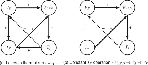
Thermal runaway can be prevented by controlling current over variations in supply voltage, temperature, and over LED-to-LED variations caused by manufacturing errors. When LEDs are driven under constant current, forward voltage decreases with the increase in junction temperature, as junction temperature stabilizes under thermal equilibrium, forward voltage also reaches its steady state value without resulting in “Thermal runaway”, as illustrated in .
Thermal management system plays a major role in making sure that junction reaches steady state at earliest and thereby improving LED performance and reliability. The rated maximum forward current of a LEDs is generally de-rated as ambient temperature increases and also for ensuring lifetime and reliability, it is important not to violate the LEDs absolute maximum current rating, hence constant current operation is the preferred method to drive LEDs (Mu et al., Citation2011).
4.1. Driving LEDs with constant current
An LED’s luminance is determined by forward current and it is more significant in terms of LED operation than forward voltage. This behavior of an LED requires LEDs to be better driven with a fixed current rather than constant voltage applied across them (Chen, Li et al., Citation2016; Hegedüs et al., Citation2017; Semiconductors, Citation2017a). So precise adjustments of brightness can only be achieved using current control. Proper driving of LEDs is critical to address some of the basic differences that all LEDs may have due to manufacturing errors (Koshel, Citation2008; Semiconductors, Citation2011a). LEDs emit light under forward bias conditions when the voltage across the junction is above a minimum threshold value suitable for the onset of current flow across the junction. Upon reaching the threshold voltage, the current and light output increases exponentially with the forward voltage existing across the junction as seen in Equationequation (6)(6)
(6) . This behavior of an LED requires LEDs to be better driven with a fixed current rather than constant voltage applied across them (Chen, Xiao et al., Citation2016; X. Liu et al., Citation2016).
Constant current operation avoids violating rated maximum current to obtain desired light distribution and color characteristics (Maxim, Citation2004). Further, non-linear electrical characteristics of LEDs and linear relationship between forward voltage and junction temperature as seen in Equationequations (6)(6)
(6) and (Equation9
(9)
(9) ) requires constant current control to avoid thermal run-away as discussed in , as junction temperature increases during LED operation if current is kept constant, forward voltage drops and avoids any harm to the LEDs (Wang et al., Citation2017).
No doubt, LEDs are current-driven devices, but there are several options on the market to choose from a range of constant current or constant voltage solutions for LED drivers. Constant voltage solution is best suited for several parallel strings of LEDs, where current in all the strings needs to be identical. In this scheme in addition to constant voltage source across the parallel LED strings, current limiters in series with the power supply are needed to match and regulate the current flow in all the parallel strings. This will be an inefficient solution owing to losses in the current limiter, but will ensure identical current flow in all the parallel LED strings. However, for series connected LEDs strings, the most efficient way to drive them is using a constant current source (Chen, Li et al., Citation2016; Hegedüs et al., Citation2017).
LED drive circuitry is critical in ensuring long life and reliability of LEDs contained in a luminaire. Driving LEDs correctly avoids situations like thermal run-away. Driving with constant voltage source without current limitation will result in thermal run-away. Hence LEDs powered by constant voltage drivers are provided with in-built current control (Vossloh-Schwabe Lighting, Citation2014; Wang et al., Citation2017).
A comparison of LED-driving circuits based on electrical characteristics is presented in (Nogawa, Citation2014; Rust et al., Citation2013). When a constant voltage is applied across a bare LED as shown in , the LED conducts with enough forward voltage across it and emits light. As seen in Equationequation (6)
(6)
(6) , is not an appropriate way of driving an LED because for a small change in forward voltage
there is a large change in forward current
, hence for every change in supply voltage, brightness of LED keeps on changing and it acts like a flash bulb.
Circuit representation for LEDs driven using an external series resistance to limit forward current and protect them as shown in . Given a constant supply voltage
and series resistance
, operating forward current is given by Equationequation (12)
(12)
(12) ,
From , the operating current is determined by the point of intersection of the load-line () with the LED’s characteristic curve, so any variation in LED’s characteristic curve and series resistance due to manufacturing errors can affect the forward current, in simple terms
. This method is appropriate for noncritical LED applications. This is the simplest way to drive LEDs, but also inefficient way to power LEDs. As seen in Equationequation (12)
(12)
(12) , depending on supply voltage, the power consumed by the series resistance can be significant. Further, at constant voltage drives tolerances on the voltage source will affect LED current, thereby affecting light output, color characteristics and efficacy of the luminaire. Further forward voltage and junction temperature mismatch cannot be addressed with this method.
As already discussed that LED light output is dependent on forward current, hence for critical illumination applications current control is more appropriate. Increase in applied voltage drop across the LED doesn’t increase significantly due to its non-linear characteristics, but on the other hand forward current increases as seen from Equationequation (12)(12)
(12) , to limit this current appropriate sized series resistance
can be used. Constant current drive is the best to maximize light output and keep forward current within safe limits.
There is variation in terms of light output and color characteristics from one LED to another LED due to manufacturing errors. The only way to achieve desired characteristics from an LED is to drive it at current stated in the data-sheet as specified by the manufacturer. Dimming and brightness control of LEDs is only possible with current regulation as specified in the data-sheets. Operating LEDs outside its specifications will lead to unacceptable changes in light output and color characteristics. This is further aggravated due to variation in terms of light output and color characteristics from one LED to another LED due to manufacturing errors (Semiconductors, Citation2011a). Constant current control shown in eliminates the use of current limiting resistors and regulates current at desired levels irrespective of variation in forward voltage due to change in junction temperature or manufacturing errors.
5. Piecewise-linear model of LED from electrical characteristics
The electrical characteristics of LED can be represented in the form of an equivalent circuit made of linear components carefully chosen to best represent the actual terminal characteristics of the LED in a particular operating region. This equivalent circuit can now be analyzed using traditional circuit analysis methods and techniques. Piecewise-linear (PWL) method approximates the characteristic curve of the LED to straight-line segments for obtaining an equivalent circuit, as illustrated in . Using PWL models the characteristics curve is translated to linear arithmetic (Leenaerts & Bokhoven, Citation1998; Rewienski & White, Citation2003; Zhang et al., Citation2012). It must be understood that the PWL model does not represent an exact replication of the true LED electrical characteristics, however, the resulting straight-line segments are reasonably close to the true characteristics and will help to establish an equivalent circuit that will represent an excellent first-level approximation of the actual LED behavior (Boylestad & Nashelsky, Citation2012). In , electrical characteristics of DURIS P8 GW PUSRA1.PM manufactured by OSRAM (Semiconductors, Citation2017b) represented using piecewise-linear model.
Figure 7. Electrical characteristics of DURIS P8 GW PUSRA1.PM manufactured by OSRAM represented using piecewise-linear model. the model parameters are extracted from the electrical characteristics and represented in a equivalent circuit
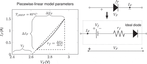
Minimum forward voltage required for an LED to be conducted in the forward bias condition is known as the “Knee voltage” or the “Threshold voltage”, represented as
in . Diode acts as a switch in forward bias condition, with theoretically zero resistance to the flow of forward current from anode to cathode. As seen in , on attaining
, diode starts to conduct with current increasing exponentially for small changes in
as seen in Equationequation (6)
(6)
(6) . In reality some finite resistance is offered by the LED junction for the flow of forward current under forward bias, this is the natural resistance of the LED junction and depends on the material and structure of the junction. The change
, beyond
is caused by forward current
flowing through the resistance of the junction, hence the characteristics beyond
have a slope where voltage varies with current. This resistance is known as “average ac resistance” or “bulk resistance”.
In the PWL model represents the voltage required to overcome the barrier potential of LED, hence it is shown opposing the direction of conduction and signifies that voltage across the LED must be greater than
, so that the conduction in the direction dictated by ideal diode can be established. The ideal diode in the PWL model represents a one-way conduction through the LED. The resistance
, represents the forward bias resistance of the LED. So, the forward voltage can be represented as the sum of knee voltage and drop across the bulk resistance as shown in (13),
Bulk resistance is estimated by calculating the slope of electrical characteristics for maximum and minimum values of input voltages as shown in . For the LED considered in , the bulk resistance
is calculated as shown in (14),
5.1. Temperature-dependent PWL model of a light-emitting-diode
Temperature-dependent PWL model of the LED is obtained by establishing temperature dependence of knee voltage and series resistance
as shown in . The PWL characteristics of the LED can be expressed in the form of slope and intercept of
characteristics as in (15), where
is the intercept and
is the slope (Poppe, Citation2015).
Figure 8. Deriving temperature-dependent PWL model of LED from temperature dependence of electrical characteristics
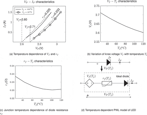
The values of and
are obtained for different junction temperatures
as illustrated in for DURIS P8 GW PUSRA1.PM white LED manufactured by OSRAM (Semiconductors, Citation2017b). Temperature dependence of
and
is plotted in respectively. As seen from the temperature-dependent characteristics, higher forward voltage is required at lower junction temperature to conduct the diode in forward bias condition, also the bulk resistance
reduces marginally with increase in junction temperature.
With this a generalized temperature dependent PWL model of an LED can be realized, where knee voltage can be represented as junction temperature-dependent voltage source and bulk resistance as a thermistor represented in . The approximate electrical circuit of an LED under forward bias condition driven by a current source is shown in , most of the models discussed in literature (Almeida et al., Citation2015; Bender et al., Citation2012, Citation2013; University of Colorado Boulder, Citation2017) have represented power supply in the diode model as a constant current source representing the forward current .
Figure 9. LED equivalent circuit driven by current source, derived from PWL model of electrical characteristics. Approximate electrical equivalent circuit of an LED under forward biased condition ()
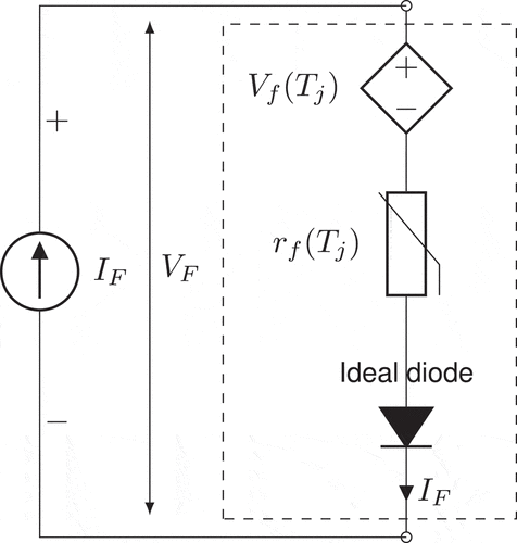
Equivalent circuit of LED derived by fitting PWL to its electrical characteristics is shown in . LED presents a very low resistance under forward bias, as seen from Equationequation (14)(14)
(14) and , the variation of
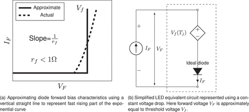
is negligible with junction temperature and is less than 1 ohms. For a fully conducting illumination grade high-power LED the voltage drop lies in a narrow range: approximately 0.2–0.3 V (Semiconductors, Citation2017b). An even simplified model of the LED forward characteristics is obtained if the effect of resistance
is neglected and a vertical straight line is used to approximate the fast rising part of the exponential curve as shown in . The resulting model represents that a forward conducting diode exhibits a constant voltage drop
as seen in . The simplified constant-voltage-drop model of the LED forward characteristics and its equivalent-circuit representation is shown in . The constant-voltage-drop model shown in is the one most often used in the initial phases of design and analysis. This is especially true if at initial design stages detailed information about the LED characteristics is not known, which is most often the case.
6. Heat generation and dissipation from light-emitting diodes
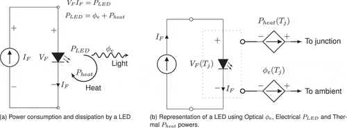
A portion of electrical energy () supplied to an LED is converted into optical power or radiant flux
and rest is dissipated as
in the form of heat as shown in and represented as per Equationequation (16)
(16)
(16) . The amount of waste heat generation is dependent on the optical efficiency of the LED
, it relates the radiant power
produced for given power input
as shown in Equationequation (17)
(17)
(17) . The dissipated power
must be conducted away from the LED junction, failing to do so will result in a situation like thermal run-away. Hence it is critical to limit the junction temperature
to a value that is within safe limits to ensure desired LED lifetime (Tsai et al., Citation2007), exceeding the absolute maximum ratings as specified by the manufacturer, may cause irreversible damage to the LED and cause permanent shifts in performance over the lifetime. Hence it is critical to dissipate the heat generated away from the LED and into the ambient, however the effectiveness with which heat is dissipated away from the LED is dependent on the thermal resistance along the heat dissipation path from the LED to the ambient.
Figure 11. A fraction of electrical power applied to a LED is converted into visible light
and rest needs to be dissipated as waste heat
6.1. Thermal path from the light-emitting diode to the ambient
LEDs are enclosed in a transparent resin which has poor thermal conduction properties, hence nearly all heat to be dissipated needs to be conducted through the rear side of the LED device. Heat generated at the LED junction must be conducted to the ambient via all the thermal interface materials (TIMs). Heat needs to be conducted away from the LED junction to the solder point, then to heat sink via the board and finally to the ambient.
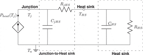
Dynamic thermal model of an LED mounted on a heat sink is shown in . In the dynamic thermal model shown in , the power to be dissipated is represented as temperature-dependent thermal current source, node voltages represent temperature and resistance-capacitance (RC) network represents thermal resistance and capacitance. The thermal RC network from junction-to-ambient represents thermal properties of the thermal-interface-materials from junction-to-ambient (Lai et al., Citation2015; Natarajan et al., Citation2013).
Figure 12. Dynamic thermal model and compact thermal model of an LED mounted on a heat sink. one dimensional heat conduction path from junction-to-ambient in a LED

LED package thermal RC network from junction-to-heat sink is represented as lumped resistance and capacitance
in the compact thermal model shown in , a lumped thermal RC model reduces the complexity of computation and representation posed by distributed RC models. The lumped model also simplifies the modeling approach, however, there are concerns on using lumped RC models and their accuracy compared distributed RC models as seen in , however lumped RC models have been successfully used in studying microelectronics circuitry and other applications (Bahman et al., Citation2016; Hui, Citation2017; Lasance & Poppe, Citation2014; Panão et al., Citation2016) where time constants involved are much smaller compared to heat sink time constants, for empirical studies in depth detailing of thermal RC interconnect network from junction to heat sink is not needed. An equivalent dynamic compact thermal model of an LED mounted on a heat sink is presented in , where two nodes are considered for representing junction temperature
and heat sink temperature
, thermal RC parameters of heat sink are represented as
and
.
6.2. Thermal metric for light-emitting diodes
There exists a spatial temperature difference between the heated junction of an LED and a well-defined reference point or the ambient under thermal equilibrium. Temperature of the heated junction is mathematically expressed using Equationequation (18)
(18)
(18) , where
is the thermal resistance provided by the manufacturer from the junction to the reference point,
is the heating power to be dissipated, and
, is a reference temperature, it can be either temperature of the ambient or of a point on the package or board.
Thermal resistance, is a very good thermal metric for assessing the thermal design of an LED device or product. Accurately estimating
is critical in providing figure-of-merit for thermal design and also valuable for projecting long-term performance and lifetime (Lasance, Citation2008; Poppe & Lasance, Citation2009, Citation2008) of LED products. Knowing
is key to keep the operating junction temperature under safe limits as specified by the manufacturer, exceeding which will compromise device lifetime. Thermal resistance,
is calculated using Equationequation (19)
(19)
(19) by rearranging Equationequation (18)
(18)
(18) ,
Junction temperature and junction-to-reference point thermal resistance serve to achieve better thermal performance of LED device and to establish figure-of-merit reference values to compare similar products. Usually junction-to-reference point thermal resistance values are preferred for such purposes. Luminaire designers require thermal resistance values for studying different scenarios and come up with accurate junction temperature predictions, using which other key properties of LEDs can also be predicted. Mutual dependency of optical, electrical and thermal characteristics makes LED operation complex, standardized multi-domain models representing actual operation of LEDs in actual application environments will assist in analyzing their multi-domain performance.
For un-heated device, in its initial thermal equilibrium, initial junction temperature is the same as the reference point temperature
or ambient temperature
depending on the reference point definition. Junction temperature changes with dissipated power, if the junction temperature
at the beginning corresponds to a dissipated power of
, and the final junction temperature
corresponds to a dissipated power of
, for both cases we can express junction temperature as per Equationequation (20)
(20)
(20) ,
Junction to reference point thermal resistance is also expressed as (21) by measuring the change in junction temperature from
to
and rearranging the terms,
With the exception of junction temperature , temperature of any reference point which is easily accessible can be measured directly. For example, the most commonly used reference point for any LED product is the heat-sink, its temperature
shown in can be easily measured directly. Knowing the temperature of the heat sink
and the power to be dissipated
, thermal resistance
of the heat sink is calculated according to Equationequation (22)
(22)
(22) , where
represents ambient temperature.
Hence under thermal equilibrium, knowledge of ,
and junction-to-heatsink thermal resistance
is key in estimating junction temperature as per Equationequation (23)
(23)
(23) ,
According to application notes of reputed LED manufacturers, as a rule of thumb only 25% of the applied electrical power to LED is converted into visible light (Bridgelux, Citation2011; Cree, Citation2016; Lumileds, Citation2015). In the absence of accurate data regarding power to be dissipated, can be assumed from conservative estimate to be 75% of applied electrical input, there are examples where data sheets recommend using the applied electric power
to estimate electrical thermal resistances (Semiconductors, Citation2011b, Citation2011c).
Some manufacturers prefer to express thermal resistance in terms of applied electrical power instead of heating power
. Definition of thermal resistance changes from how denominator in (19) is defined for calculating thermal resistance (Lumileds, Citation2015; Semiconductors, Citation2011b). According to the electrical thermal resistance definition denominator in (19) as applied electrical power (
) in contrast real thermal resistance defines denominator as the difference between applied electrical power
and emitted radiant power or optical power
. In the absence of approximate data for dissipated power
, as per rule of thumb light output or luminous flux can be converted into its electrical equivalent (Semiconductors, Citation2011b), for white LEDs as a conservative estimate, luminous flux of 100 lumen is approximately equivalent to 320 mW of electrical power.
The electrical thermal resistance as discussed earlier is shown in (24) and (25) for heat sink and junction-to-ambient respectively,
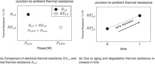
The comparison between electrical and real thermal resistance is shown in , the value of electrical thermal resistance RE compared to real thermal resistance is less because the dissipated power is less than the power input
as
. Due to aging and degradation of thermal interface materials thermal resistance increases with time, this can be seen in . Hence thermal resistance is an important parameter to assess aging and performance degradation levels.
7. Multi-domain compact models of light-emitting diodes
There are several studies on developing multi-domain LED model discussed in literature (Farkas et al., Citation2016; Poppe, Citation2012; Poppe, Farkas, Szekely et al., Citation2006; Poppe & Szalai, Citation2014; Poppe & Temesvölgyi, Citation2013). These studies have highlighted that a typical multi-domain model of an LED should include optical, electrical and thermal parameters and their interrelationships. The model should represent physics of LED operation without going in to details like structure or material of LED device (Poppe, Citation2015). It is important to represent the models as subsystems independent of each other so that these models at subsystem level provide sufficient input information for other models.
7.1. End-users of multi-domain compact model and their requirements
Delphi4LED, a group working on developing a standard procedure to create multi-domain LED-based design for the SSL industry has identified following end-user groups (Alexeev et al., Citation2017) of who require MCM of LEDs. They can be from different organizations and industries ranging from small enterprises to large manufacturers of SSL products, they are,
• LED experts and product system architects
• Thermal management designers
• Electronics engineers
• Lighting engineers
• Optics designers
The LED experts are responsible for selecting the best LED with accurate and reliable specifications for a given project. MCM for such users will help to accurately predict best operating points in different system architectures, and carry out benchmarking of products. Thermal requirements for an LED product are defined based on long-term performance, useful life, thermal metric, power dissipation, package geometry and maximum operating temperature.
Thermal requirements for an LED product are defined based on long-term performance, useful life, thermal metric, power dissipation, package geometry and maximum operating temperature. Thermal engineers perform simulations on LED thermal models in their operating environment to predict operating temperature to determine whether the design is fulfilling the thermal requirements. Using MCM of LEDs electronics engineers perform electrical simulations to design drivers, and identify any other electrical requirements for LED luminaires. Optical designers are more focused on photometry, they will use the MCM for predicting efficacy, total luminous flux and color properties in actual application environment.
End-users face many problems depending on the purpose of the SSL products. LED data-sheets are not standardized among the manufacturers. Incomplete information limits the potential benefits and innovation related with the application of new LED products. Most of the time datasheets do not report appropriate thermal resistance values. Dynamic thermal characteristics are never listed in data-sheets, only static values are reported. Shifting of performance parameters over time is not reported in LED data-sheets. It is crucial to create the MCM models from OET characteristics where test data are reported in standardized e-data-sheet formats and are accessible worldwide. Only through analysis of the LED performance metrics based on the actual application and intended environment can an appropriate selection decision be made this can be realized only by having standardized MCM models of LEDs.
7.2. Parameters and recommendations for light-emitting diode MCM Development
Some of the key OET parameters which need to be included in the MCMs are listed in . Whether a parameter is an input or output depends on the context of measurement or analysis. For example, junction temperature and forward current would determine the forward voltage in electrical model of an LED. Luminous flux is the basic photometric parameter for any light source that measures the amount of emitted radiation perceived by the human eye, hence it needs to be addressed accurately in a multi-domain model of an LED.
Table 1. Parameters for multi-domain compact model development for LEDs
Junction temperature affects multi-domain LED performance parameters, as well as electrical power consumed. It is one of the most crucial output parameters of a compact model. For a proper thermal analysis of an LED, several temperatures need to be considered on an individual basis. These are junction, heat-sink and ambient temperatures. There is no direct way to measure junction temperature due to miniature size of the pn-junction and inability to access it in a non-destructive way. Heat-sink temperature is one of the most important boundary conditions for modeling, because major portion of the heat generated in LED is conducted towards the ambient via the heat-sink. Junction temperature is directly dependent on heat-sink and ambient temperature. Therefore, often it has to be implicitly estimated. Ambient temperature surrounding an LED and its system influence the thermal aspects of the LED. The two-diode Spice-like electro-thermal-optical model of LEDs with a serial resistor representing the light emission is proposed by Delphi4LED project (Hantos et al., Citation2017), instead of using two parallel diodes a single diode and an efficiency model can be derived. Further, for accurately measuring junction temperature, it is important to control driving current and forward voltage, significant inaccuracies in current and voltage measurements might result in as high variations in actual values of the LED junction temperatures (Onushkin et al., Citation2017).
7.3. Multi-domain compact model of a light-emitting diode mounted on a heat-sink
Prominent work in the field of multi-domain modeling of LEDs and LED luminaires containing array of LEDs (Hui et al., Citation2012; Hui & Qin, Citation2009; Negrea et al., Citation2012; Poppe et al., Citation2016; Poppe & Temesvölgyi, Citation2013; Tao & Hui, Citation2012; Weilguni et al., Citation2010), have considered junction temperature as voltage between the junction node of the model and thermal reference point equivalent to ambient temperature
as seen in . In literature, heating power
is represented as a constant thermal current source factored by a constant dependent on junction temperature; this heating power needs to be dissipated into the ambient through the thermal path from the junction-to-ambient. The radiant flux or optical power
escapes into the ambient through the optics of the LED. It is common practice to represent temperatures as node voltages and heating powers as thermal currents, drawing an analogy with electrical circuits consisting of node voltages and current sources.
Figure 15. Optical, Electrical and Thermal model of an LED mounted on a heat-sink. this model is represented using single diode rather two parallel diodes as discussed in existing literature
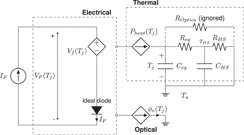
The optical and heating powers explicitly or implicitly depend on all branch voltages of the electro-thermal model. Multi-domain models of LEDs discussed in literature contain two parallel diode representation to show forward current as a combination of currents responsible for radiative and non-radiative processes(Baureis, Citation2005). However, in this work the LED characteristics are modeled using single ideal diode in series with a junction temperature-dependent voltage source, as seen in . The existing LED models discussed in literature require complex measurements to represent the mutual dependency of thermal and electrical systems in the form of electro-thermal and thermo electrical trans-conductances (Poppe, Citation2012).
In this work detailing of optical power and heating power is represented as dependent current sources as seen in , further the model is simplified to represent electro-thermal representation by omitting optical power from the model. Heating power is represented as controlled or dependent sources (Górecki, Citation2012), where the controlling voltage source is the junction temperature
, hence heating power
is represented as a function of
. Opto-Electro-Thermal model of LED is presented in , by decoupling the three domains. From the model it can be seen that by knowing heating power
and heat-sink temperature
junction temperature
can be estimated by applying Kirchhoff's voltage and current laws to the thermal circuit as it is analogous to an equivalent electrical circuit.
Thermal transient measurement helps to model LED packages for which no reliable manufacturer data sheet is available. There are industrial laboratory testing standards published by JEDEC supporting thermal transient testing. Standards are defined for measuring junction-to-case thermal resistance (JEDEC, Citation2010) and measuring real thermal resistance considering optical power emitted by the device. By means of transient thermal measurements complaint with JEDEC (Joint Electron Device Engineering Council) standard (JEDEC, Citation2010, Citation2012a, Citation2012b, Citation2012c) it is possible to obtain compact thermal model of LEDs (Poppe, Farkas, Szekely et al., Citation2006; Poppe, Farkas, Horvath et al., Citation2006). Measured thermal transient is converted into a generic Cauer-type RC ladder model which best describes at the LED level a single junction-to-ambient heat-flow path as seen in , this followed by structure function analysis (Székely & Bien, Citation1988) is a perfect means to measure and monitor thermal resistances for reliability testing, and thermal modeling for designing system-level thermal management solutions. The measurements required to build a compact multi-domain model of an LED are thermal and radiometric so that actual heating power can be measured. With the same experimental set-up (Paisnik et al., Citation2012), (Poppe et al., Citation2010) it is possible to measure electrical parameters as a function of junction temperature.
In a comprehensive LED compact multi-domain model, LED thermal model is driven by junction node: the power to be dissipated is fed into the LED thermal model as in . A simple approach is considered in this work to model multi-domain characteristics of an LED; the model is built around an operating point considering constant current operation as discussed earlier. One of the objectives was to provide comprehensive LED model parameters which can be identified from combined optical, electrical and thermal characteristics. In literature on multi-domain LED models (Alexeev et al., Citation2017; Bornoff et al., Citation2016; Poppe, Citation2017; Poppe et al., Citation2016; Poppe & Szalai, Citation2014), LED is considered as a set of two parallel diodes connected across the same forward voltage, where one diode emits only heat and other emits only light, this model also includes compact thermal model of the LED package and its thermal environment. The optical model is treated as black box model without dealing with physical details of the energy conversion process and losses associated with it.
The multi-domain compact model shown in is modular where thermal part is decoupled from electrical and optical model, the interface point for all three models is the junction node similar to an electrical circuit with junction temperature as node voltage and power to be dissipated represented as node current. This model can be created from thermal transient measurements compliant with JEDEC standards. Knowing the optical efficiency of the LED allows inclusion of optical properties into the model. Temperature dependence of all model parameters is measured with respect to single reference temperature , in this work ambient temperature
is the reference temperature. This temperature represents the ambient conditions in which LED operates so that the model represents actual working characteristics with highest possible accuracy in the considered temperature range.
8. Conclusion
Light-emitting diodes operate in multiple domains simultaneously, this nature of theirs makes it challenging to characterize their operating parameters. One of the key challenges in designing LED lighting products is to manage the mutual dependency between thermal, electrical, and optical performances. A major challenge for designing LED-based lighting products is the temperature and driving current dependence of their performance. In order to achieve a high-performance design of LED products, a modular, multi-domain-based modeling approach is required, thereby allowing the freedom for LED luminaire designers to use such models in any kind of lighting fixture design. In order to overcome challenges in LED luminaire design, seamless integration of the LED in the luminaire development process is essential. For that a bridge, in the form of standardization, has to be established between the LED industry and the luminaire manufacturers. This is possible if the tools like Standard multi-domain model of LED packages, Compact thermal models of LED packages and Luminaire modeling interfaces are provided. From the theory proposed in this work, methodology to create multi‐domain LED compact models from testing data is comprehended. Future work in this includes performance assessment of high-power LEDs using multi-domain models generated using data-sheet information.
Additional information
Funding
Notes on contributors

Shailesh K R
Shailesh K R received B.E. degree in Electrical and Electronics engineering from Mangalore University, India, in 1997 and M.Tech. degree in illumination technology from Mangalore University, India, in 1999. He received a Ph.D. degree for the thesis titled “Assessment of light-emitting diode luminaire performance using virtual test bench” from Manipal Academy of Higher Education, India in 2019. He is the author of more than 40 technical papers published in reputed international journals and international conference proceedings. His notable contributions include a new method of gonio-photometry known as “Light Sieve Photometry” and a non-invasive method to measure the junction temperature of LEDs in an LED luminaire. His research interests are in the area virtual instrumentation for light and light-based technologies. The work discussed in this work brings together the knowledge provided by LED manufacturers, academicians and software developers in creating compact multi-domain models of light-emitting diodes.
References
- Alexeev, A., Bornoff, R., Lungten, S., Martin, G., Onushkin, G., Poppe, A., Rencz, M., & Yu, J., “Requirements specification for multi-domain led compact model development in delphi4led,” in 2017 18th International Conference on Thermal, Mechanical and Multi-Physics Simulation and Experiments in Microelectronics and Microsystems (EuroSimE), (Dresden, Germany), pp. 1–25, 3–5 April 2017.
- Alexeev, A., Onushkin, G., Linnartz, J.-P., & Martin, G. (2019). Multiple heat source thermal modeling and transient analysis of LEDs. Energies, 12(no. 10), 1860. https://doi.org/10.3390/en12101860
- Almeida, P. S., Bender, V. C., Braga, H. A. C., Costa, M. A. D., Marchesan, T. B., & Alonso, J. M. (2015, July). Static and dynamic photoelectrothermal modeling of led lamps including low-frequency current ripple effects. IEEE Transactions on Power Electronics, 30(7), 3841–3851. https://doi.org/10.1109/TPEL.2014.2340352
- Arnold, J. (2004). When the lights go out: LED failure modes and mechanisms. In Prepared for DfR Solutions.
- Bahman, A. S., Ma, K., Ghimire, P., Iannuzzo, F., & Blaabjerg, F. (2016, September). A 3-D-Lumped thermal network model for long-term load profiles analysis in high-power igbt modules. IEEE Journal of Emerging and Selected Topics in Power Electronics, 4(3), 1050–1063. https://doi.org/10.1109/JESTPE.2016.2531631
- Baran, K., Różowicz, A., Wachta, H., & Różowicz, S. (2020). Modeling of selected lighting parameters of led panel. Energies, 13(no. 14), 3583. https://doi.org/10.3390/en13143583
- Baureis, P., “Compact modeling of electrical, thermal and optical led behavior,” in Proceedings of 35th European Solid-State Device Research Conference, 2005. ESSDERC 2005., (Grenoble, France), pp. 145–148, Sept 2005. 16.
- Bender, V. C., Iaronka, O., Costa, M. A. D., do Prado, R. N., & Marchesan, T. B. An optimized methodology for LED lighting systems designers. 2012 IEEE Industry Applications Society Annual Meeting. 1–8. 7–11 Oct 2012
- Bender, V. C., Iaronka, O., Vizzotto, W. D., Costa, M. A. D., do Prado, R. N., & Marchesan, T. B. (2013, November). Design methodology for light-emitting diode systems by considering an electrothermal model. IEEE Transactions on Electron Devices, 60(11), 3799–3806. https://doi.org/10.1109/TED.2013.2282901
- Bogart, T. F., Beasley, J. S., & Rico, G. (2009). Electronic Devices and Circuits (6 ed.). Pearson Education India.
- Bornoff, R., Hildenbrand, V., Lugten, S., Martin, G., Marty, C., Poppe, A., Rencz, M., Schilders, W. H. A., & Yu, J. 2016. Delphi4led - from measurements to standardized multi-domain compact models of led: A new european r d project for predictive and efficient multi-domain modeling and simulation of leds at all integration levels along the ssl supply chain. 22nd International Workshop on Thermal Investigations of ICs and Systems (THERMINIC). 174–180. 21–23 Sept. 2016
- Boylestad, R. L., & Nashelsky, L. (2012). Electronic Devices and Circuit Theory (11 ed.).
- Bridgelux, “Effective thermal management of bridgelux LED arrays.” Application Note AN10, 2011.
- Chen, K., Li, M., Xiao, P., & Johnsen, A. (2016). Design of LED constant current controller using multi-channel current-sharing topology. Microelectronics Journal, 57(no. Suppl. C), 52–59. https://doi.org/10.1016/j.mejo.2016.09.004
- Chen, K., Xiao, P., Johnsen, A., & Saenz, R. E. (2016, July). Turn-on optimization for class d series parallel lcc-type constant current high-power led driver design based on traditional fluorescent control ic. IEEE Transactions on Power Electronics, 31, 4732–4741.
- Cree, “Thermal management of cree XLamp LEDs.” Application Note, 2016.
- Dulout, J., Barroso, A., Séguier, L., Jammes, B., Dupuis, P., Zissis, G., & Alonso, C. Multi-objective methodology to find the optimal forward current to supply light emitting diode (LED) lightings. 2016 IEEE industry applications society annual meeting. 1–7. 2–6 October 2016
- Elger, G., Müller, D., Hanß, A., Schmid, M., Liu, E., Karbowski, U., & Derix, R. (2016). Transient thermal analysis for accelerated reliability testing of LEDs. Microelectronics Reliability, 64, 605–609. https://doi.org/10.1016/j.microrel.2016.07.094
- Fan, J., Yung, K. C., & Pecht, M. 2011. Failure modes, mechanisms, and effects analysis for LED backlight systems used in LCD tvs. Prognostics and System Health Management Conference. 1–5. 24–25 May 2011
- Farkas, G., Bein, M. C., & Gaál, L. 2016. Multi domain modelling of power LEDs based on measured isothermal and transient I-V-L characteristics. 22nd International Workshop on Thermal Investigations of ICs and Systems (THERMINIC). 181–186. 21–23 Sept. 2016
- Gao, Y., Zhang, H., Guo, X., Cao, F., Yu, J., Chen, A., & Zou, N. (2015, December). Method to design alternating current light-emitting diodes luminous flux. Optical and Quantum Electronics, 47(12), 3715–3727. https://doi.org/10.1007/s11082-015-0241-z
- Górecki, K. (2012). Electrothermal model of a power led for spice. International Journal of Numerical Modelling: Electronic Networks, Devices and Fields, 25(no. 1), 39–45. https://doi.org/10.1002/jnm.811
- Górecki, K., & Ptak, P. (2020). Thermal, photometric and radiometric properties of multi-color LEDs situated on the common pcb. Electronics, 9(no. 10), 1672. https://doi.org/10.3390/electronics9101672
- Górecki, K., & Ptak, P. (2021). Compact modelling of electrical, optical and thermal properties of multi-colour power LEDs operating on a common pcb. Energies, 14(no. 5), 1286. https://doi.org/10.3390/en14051286
- Grodzki, L. (2013). The comparison of the pulse and constant-current LED driving. Przeglad Elektrotechniczny, (no. 11), 298–300.
- Halkias, C. C., Millman, J., & Jit, S. (2012). Electronic Devices and Circuits (3 ed.). Pearson Education India.
- Hantos, G., Hegedüs, J., Bein, M. C., Gaál, L., Farkas, G., Sarkany, Z., Ress, S., Poppe, A., & Rencz, M., “Measurement issues in led characterization for delphi4led style combined electrical-optical-thermal led modeling,” in 2017 IEEE 19th Electronics Packaging Technology Conference (EPTC), (Singapore), pp. 1–7, 6–9 December. 2017.
- Hegedüs, J., Hantos, G., & Poppe, A. (2017). Light output stabilisation of LED based streetlighting luminaires by adaptive current control. Microelectronics Reliability, 79(no. Suppl. C), 448–456. https://doi.org/10.1016/j.microrel.2017.06.060
- Hui, R. (2017). Photo-Electro-Thermal Theory for LED Systems: Basic Theory and Applications. Cambridge University Press.
- Hui, S. Y., & Qin, Y. X. (2009, August). A general photo-electro-thermal theory for light emitting diode (LED) systems. IEEE Transactions on Power Electronics, 24(8), 1967–1976. https://doi.org/10.1109/TPEL.2009.2018100
- Hui, S. Y. R., Chen, H., & Tao, X. (2012, November). An extended photoelectrothermal theory for led systems: A tutorial from device characteristic to system design for general lighting. IEEE Transactions on Power Electronics, 27(11), 4571–4583. https://doi.org/10.1109/TPEL.2012.2188648
- Hurtig, C., Jackson, W., & Martindale, R., “Transistor and diode studies,” tech. rep., Research Laboratory of Electronics (RLE) at the Massachusetts Institute of Technology (MIT), 1957.
- Janicki, M., Ptak, P., Torzewicz, T., & Górecki, K. (2020). Compact thermal modeling of modules containing multiple power LEDs. Energies, 13(no. 12), 3130. https://doi.org/10.3390/en13123130
- Janicki, M., Torzewicz, T., Ptak, P., Raszkowski, T., Samson, A., & Górecki, K. (2019). Parametric compact thermal models of power LEDs. Energies, 12(no. 9), 1724. https://doi.org/10.3390/en12091724
- Jayawardena, A. Y. wei Liu, and N. Narendran, (2013). “Analysis of three different junction temperature estimation methods for ac LEDs.” Solid-State Electronics, 86, 11–16. https://doi.org/10.1016/j.sse.2013.04.001
- JEDEC, “Transient dual interface test method for the measurement of the thermal resistance junction-to-case of semiconductor devices with heat flow through a single path,” standard, JEDEC, Arlington, VA, November 2010.
- JEDEC, “Overview of methodologies for the thermal measurement of single- and multi-chip, single and multi-pn junction light-emitting diodes (LEDs),” standard, JEDEC, Arlington, VA, April 2012a.
- JEDEC, “Implementation of the electrical test method for the measurement of the real thermal resistance and impedance of light-emitting diodes with exposed cooling surface,” standard, JEDEC, Arlington, VA, April 2012b.
- JEDEC, “Guidelines for combining CIE 127–2007 total flux measurements with thermal measurements of LEDs with exposed cooling surface,” standard, JEDEC, Arlington, VA, April 2012c.
- Keppens, A., Ryckaert, W., Deconinck, G., & Hanselaer, P., “Evaluation of current and temperature effects on high power light-emitting diode efficiencies,” in CIE Conference Budapest June 2009, (Budapest), CIE, 1–3 June 2009.
- Koshel, R. J., “SSL design with LED binning tolerances,” in Proc.SPIE, vol. 7103, (Glasgow, Scotland, United Kingdom), pp. 7103 – 7103 – 1224 September 2008.
- Lai, W., Liu, X., Chen, W., Lei, X., & Cao, X. Dynamic compact thermal model of high power light emitting diode. (2015). Microelectronics Reliability, 55(no. 12), 2663–2670. Part B. https://doi.org/10.1016/j.microrel.2015.10.001
- Lasance, C. J., & Poppe, A. (2014). Thermal Management for LED Applications. Springer-Verlag New York.
- Lasance, C. J. M. 2008. On the standardisation of thermal characterisation of leds part i: Comparison with ic packages and proposal for action. 14th International Workshop on Thermal Investigation of ICs and Systems. 208–212. 24–26 Sept 2008
- LED basics.” Application note, September 2010.
- Leenaerts, D. M. W., & Bokhoven, W. M. V. (1998). Piecewise Linear Modeling and Analysis. Kluwer Academic Publishers.
- Li, M., Chen, K., Rupp, A., Chu, D., & Vangari, D. (2015). Luminous flux and current uniformity analysis in linear LED modules. LEUKOS, 11(no. 1), 19–29. https://doi.org/10.1080/15502724.2014.979996
- Lighting the way: Perspectives on the global lighting market.” McKinsey & Company, August 2012. 2e.
- Liu, D., Yang, H., & Yang, P. (2014). Experimental and numerical approach on junction temperature of high-power LED. Microelectronics Reliability, 54(no. 5), 926–931. https://doi.org/10.1016/j.microrel.2014.01.016
- Liu, X., & Fang, W., “Analysis on the failure modes and mechanisms of LED packaging,” in 2012 13th International Conference on Electronic Packaging Technology High Density Packaging, (Guilin, China), pp. 1500–1502, 13–16 August 2012.
- Liu, X., Xu, J., Yang, Q., & Xu, D. (2016, April). High-efficiency multi-string led driver based on constant current bus with time-multiplexing control. Electronics Letters, 52(9), 746–748. https://doi.org/10.1049/el.2016.0236
- Lu, G., Yang, S., & Huang, Y., “Analysis on failure modes and mechanisms of LED,” in 2009 8th International Conference on Reliability, Maintainability and Safety, (Chengdu, China), pp. 1237–1241, 20–24 July 2009.
- Lumileds, “Thermal management considerations for superFlux LEDs Application.” Application Note AB 20–4, 2015.
- Martin, G., Poppe, A., Lungten, S., Heikkinen, V., Yu, J., Rencz, M., & Bornoff, R. (2016, December). Delphi4LED - from measurements to standardized multi-domain compact models of light emitting diodes (LED). Electronics Cooling.
- Maxim, “Why drive white LEDs with constant current?” Application Note 3256, 2004.
- Meneghesso, G., Levada, S., Zanoni, E., Podda, S., Mura, G., Vanzi, M., Cavallini, A., Castaldini, A., Du, S., & Eliashevich, I. (2002). Failure modes and mechanisms of dc-aged gan LEDs. Physica Status Solidi (A), 194(no. 2), 389–392. https://doi.org/10.1002/1521-396X(200212)194:2<389::AID-PSSA389>3.0.CO;2-O
- Moolman, M., Koek, W., & Urbach, H. (2009, September). A method towards simulating the total luminous flux of a monochromatic high power LED operated in a pulsed manner. Opt. Express, 17(20), 17457–17470. https://doi.org/10.1364/OE.17.017457
- Mu, H., Geng, L., & Liu, J., “A high precision constant current source applied in led driver,” in 2011 Symposium on Photonics and Optoelectronics (SOPO), (Wuhan, China), pp. 1–4, 16–18 May 2011.
- Natarajan, S., Ha, M., & Graham, S. (2013, August). Measuring the thermal resistance in light emitting diodes using a transient thermal analysis technique. IEEE Transactions on Electron Devices, 60(8), 2548–2555. https://doi.org/10.1109/TED.2013.2271485
- Negrea, C., Svasta, P., & Rangu, M. 2012. Electro-thermal modeling of power LED using SPICE circuit solver. 35th International Spring Seminar on Electronics Technology. 329–334. 09–13 May 2012
- Nogawa, M., “How to design LED signage and LED matrix displays (part 1),” July 2014.
- Onushkin, G. A., Bosschaart, K. J., Yu, J., Van Aalderen, H. J., Joly, J., Martin, G., & Poppe, A. 2017. Assessment of isothermal electro-optical-thermal measurement procedures for leds. 23rd International Workshop on Thermal Investigations of ICs and Systems (THERMINIC). 1–6. 27–29 Sept. 2017
- Paisnik, K., Poppe, A., Rang, T., & Rang, G., “Physics related modeling of power LEDs,” in 2012 13th Biennial Baltic Electronics Conference, (Tallinn, Estonia), pp. 57–60, 3–5 October 2012.
- Panão, M. J. O., Santos, C. A., Mateus, N. M., & Da Graça, G. C. (2016). Validation of a lumped rc model for thermal simulation of a double skin natural and mechanical ventilated test cell. Energy and Buildings, 121, 92–103. https://doi.org/10.1016/j.enbuild.2016.03.054
- Pecht, M., Das, D., & Chang, M.-H. (2014). Introduction to led thermal management and reliability. In C. J. Lasance & A. Poppe (Eds.), Thermal Management for LED Applications (pp. 3–14). Springer New York.
- Pecht, M. G., & Chang, M.-H. (2013). Failure mechanisms and reliability issues in LEDs. In W. Van Driel & X. Fan (Eds.), Solid State Lighting Reliability: Components to Systems (pp. 43–110). Springer New York.
- Pohl, L., Hantos, G., Hegedüs, J., Németh, M., Kohári, Z., & Poppe, A. (2020). Mixed detailed and compact multi-domain modeling to describe cob LEDs. Energies, 13(no. 16), 4051. https://doi.org/10.3390/en13164051
- Poppe, A., “A step forward in multi-domain modeling of power LEDs,” in 2012 28th Annual IEEE Semiconductor Thermal Measurement and Management Symposium (SEMI-THERM), (San Jose, CA, USA), pp. 325–330, 18–22 March 2012.
- Poppe, A. Multi-domain compact modeling of LEDs: An overview of models and experimental data. (2015). Microelectronics Journal, 46(no. 12), 1138–1151. Part A. https://doi.org/10.1016/j.mejo.2015.09.013
- Poppe, A. (2017). Simulation of led based luminaires by using multi-domain compact models of LEDs and compact thermal models of their thermal environment. Microelectronics Reliability, 72(Suppl. C), 65–74. https://doi.org/10.1016/j.microrel.2017.03.039
- Poppe, A., Farkas, G., Gaál, L., Hantos, G., Hegedüs, J., & Rencz, M. (2019). Multi-domain modelling of LEDs for supporting virtual prototyping of luminaires. Energies, 12(no.10), 1909. https://doi.org/10.3390/en12101909
- Poppe, A., Farkas, G., & Horvath, G. 2006. Electrical, thermal and optical characterization of power LED assemblies. THERMINIC. 197–202. 27–29 September 2006
- Poppe, A., Farkas, G., Molnár, G., Katona, B., Temesvölgyi, T., & He, J.-W. (2010, August 18). Emerging standard for thermal testing of power LEDs and its possible implementation. Proc.SPIE, 7784(San Diego, California, US), 7784 – 7784 – 15.
- Poppe, A., Farkas, G., Szekely, V., Horvath, G., & Rencz, M., “Multi-domain simulation and measurement of power LED-s and power LED assemblies,” in Twenty-Second Annual IEEE Semiconductor Thermal Measurement And Management Symposium, (Dallas, TX, USA), pp. 191–198, 14–16 March 2006.
- Poppe, A., Hegedűs, J., Szalai, A., Bornoff, R., & Dyson, J., “Creating multi-port thermal network models of LED luminaires for application in system level multi-domain simulation using spice-like solvers,” in 2016 32nd Thermal Measurement, Modeling Management Symposium (SEMI-THERM), (San Jose, CA, USA), pp. 44–49, 14–17 March 2016.
- Poppe, A., & Lasance, C. J. M. On the standardisation of thermal characterisation of leds part ii: Problem definition and potential solutions. 14th International Workshop on Thermal Investigation of ICs and Systems. 213–219. 24–26 Sept. 2008
- Poppe, A., & Lasance, C. J. M., “On the standardization of thermal characterization of LEDs,” in 2009 25th Annual IEEE Semiconductor Thermal Measurement and Management Symposium, (San Jose, CA, USA), pp. 151–158, 15–19 March 2009.
- Poppe, A., & Szalai, A., “Practical aspects of implementation of a multi-domain led model,” in 2014 Semiconductor Thermal Measurement and Management Symposium (SEMI-THERM), (San Jose, CA, USA), pp. 153–158, 9–13 March 2014.
- Poppe, A., & Temesvölgyi, T., “A general multi-domain LED model and its validation by means of AC thermal impedance,” in 29th IEEE Semiconductor Thermal Measurement and Management Symposium, (San Jose,CA,USA), pp. 137–142, 17–21 March 2013.
- Reporting LED luminaire product performance.” Next generation lighting industry alliance with the U. S. department of energy, December 2008.
- Rewienski, M., & White, J. (2003, February). A trajectory piecewise-linear approach to model order reduction and fast simulation of nonlinear circuits and micromachined devices. IEEE Transactions on Computer-Aided Design of Integrated Circuits and Systems, 22(2), 155–170. https://doi.org/10.1109/TCAD.2002.806601
- Rust, P., Schögler, W., Pauritsch, M., & Truppe, H., “New LED driving techniques reduce power in LCD TVs,” January 2013.
- Semiconductors, O. O., “LED fundamentals - driving LEDs - resistors and linear drivers.” Application Note, 2011a.
- Semiconductors, O. O., “LED fundamentals - internal thermal resistance of LEDs.” Application Note, 2011b.
- Semiconductors, O. O., “LED fundamentals - basics of heat transfer.” Application Note, 2011c.
- Semiconductors, O. O., “Electrical characteristics of LEDs.” Application Note, 2017a.
- Semiconductors, O. O., “DURIS P8.” Data sheet V1.3, 2017b.
- Székely, V., & Bien, T. V. (1988). Fine structure of heat flow path in semiconductor devices: A measurement and identification method. Solid-State Electronics, 31(no. 9), 1363–1368. https://doi.org/10.1016/0038-1101(88)90099-8
- Tao, X., & Hui, S. Y. R. (2012, April). Dynamic photoelectrothermal theory for light-emitting diode systems. IEEE Transactions on Industrial Electronics, 59(4), 1751–1759. https://doi.org/10.1109/TIE.2011.2109341
- Tsai, P. C., Chuang, R. W., & Su, Y. K. (2007, February). Lifetime tests and junction-temperature measurement of ingan light-emitting diodes using patterned sapphire substrates. Journal of Lightwave Technology, 25(2), 591–596. https://doi.org/10.1109/JLT.2006.888234
- University of Colorado Boulder, “Light-emitting diode (LED) characteristics and luminous efficacy.” ECEN2060 Renewable sources and efficient electrical energy systems, 2017.
- Vossloh-Schwabe Lighting, “Understanding LED Driver Technology.” LED Driver Guideline EN 2/2014, 2014.
- Wang, Y., Alonso, J. M., & Ruan, X. (2017, July). A review of LED drivers and related technologies. IEEE Transactions on Industrial Electronics, 64(7), 5754–5765. https://doi.org/10.1109/TIE.2017.2677335
- Weilguni, M., Nicolics, J., Medek, R., Franz, M., Langer, G., & Lutschounig, F. 2010. Characterization of the thermal impedance of high-power led assembly based on innovative printed circuit board technology. 33rd International Spring Seminar on Electronics Technology, ISSE. 238–244. 12–16 May 2010
- Xi, Y., Gessmann, T., Xi, J., Kim, J. K., Shah, J. M., Schubert, E. F., Fischer, A. J., Crawford, M. H., Bogart, K. H. A., & Allerman, A. A. (2005). Junction temperature in ultraviolet light-emitting diodes. Japanese Journal of Applied Physics, 44(no. 10R), 7260. https://doi.org/10.1143/JJAP.44.7260
- Yao, R., Zhang, D., Zou, B., & Xu, J. (2016, December). Junction temperature measurement of alternating current light-emitting-diode by threshold voltage method. Frontiers of Optoelectronics, 9(4), 555–559. https://doi.org/10.1007/s12200-015-0533-8
- York, R. (2010). Diode temp. dependence. In Supplementary Material.
- Yuzhen, X., Sheng, X., Xiangyu, H., & Weiming, L. 2016. Study on the LED control strategy of constant luminous flux based on photoelectric model. 13th China International Forum on Solid State Lighting (SSLChina). 94–96. 15–17 Nov. 2016
- Zhang, Y., Sankaranarayanan, S., & Somenzi, F. Piecewise linear modeling of nonlinear devices for formal verification of analog circuits. Formal Methods in Computer-Aided Design (FMCAD), 2012. IEEE. 196–203 . 22–25 October 2012
- Zhou, J., Huang, J., Wang, Y., & Zhou, Z. (2016). Thermal distribution of multiple LED module. Applied Thermal Engineering, 93, 122–130. https://doi.org/10.1016/j.applthermaleng.2015.09.022

