
 ?Mathematical formulae have been encoded as MathML and are displayed in this HTML version using MathJax in order to improve their display. Uncheck the box to turn MathJax off. This feature requires Javascript. Click on a formula to zoom.
Abstract
This paper reviews the work done on science and technology of aircraft seat ejection with history, present, and futuristic interest. It is topic of interest that is receiving significant attention in the recent years due to importance of the pilot life saving during war, mishaps, and emergencies. In the early days, the ejection seats used the concept of compressed air and simple mechanical springs. The escape of the aircrew from high-speed aircraft is a serious drawback during World War (WW) II. The jumping out of aeronauts from high-speed aircraft is extremely difficult because of high blast wind pressure, turbulence around the exposed cockpit, and accelerations during the aircraft maneuvers. All these systems are dangerous and damage to the vertebra column of an aviator. As the speed of the aircraft is low, the pilot has to jump out with his parachute. However, as the speed of the aircraft increases, jumping out from the disabled aircraft with the parachute is merely a matter of luck and does not guarantee the aeronaut’s survival. Therefore, it is highly essential to use an ejection seat when damage is caused due to either the fighter or trainer plane. The ejection of the pilot is of utmost importance to the services. Hence, the lives of the pilots are crucial than saving military planes. Safeguarding the pilots from disabled aircraft plays a significant role in services such as Indian Air Force and Indian Navy since their introduction. Different policies and regulations are enforced to ensure the survival and safety of pilots. These are considered an essential area in the safety programs. Security and safety are always threat to the pilots. The novelty of this research paper is to bring about the historical developmental concepts to advanced concepts through science and technologyelated aircraft seat ejection. This paper is based on oration presented by the author on the occasion of National Science Day in Feb 2021. Therefore, an attempt is also made to highlight the important contributions made by various scientists, researchers in the frontier areas related to science and technology of ejection seat for military fighter aircraft.
PUBLIC INTEREST STATEMENT
In this research paper, an author explained about science and technology of aircraft seat evolved over a period of time. Saving pilots life in a critical situation from disabled aircraft is very significant. As pilot leaves the aircraft, there is a risk of collision with the tail fin or any other part of the aircraft structure. Therefore in several cases, fatal injury to the pilot during the ejection occurs. All these are proved hazardous, which primarily resulted in the compression structure of the vertebra. Therefore, only explosive assisted of ejection of aircraft seat is the latest and most effective. In all modern fighter aircraft, the whole ejection sequence is fully automatic once the pilot pulls the manually operated lever till he lands safely on the ground. An attempt has been made in this paper to present the historical development, including advanced concepts of sophisticated seat ejection technology during the emergency escape of pilot from disabled aircraft in adverse conditions throughout its flight envelope.
1. Introduction
An ejection seat is an explosive powered life-saving device to provide the safe and reliable means for the pilot to abandon the aircraft in the shortest possible time to save himself when the aircraft is in danger (B. Zygmunt et al., Citation2008). The ejection seat comprises a telescopic gun, harness system, parachute deployment system, rocket pack, survival pack, etc. The energy required to work against the gravity in the upward direction is provided by the propellant content in them. This energy is supplied to the entire system in installment. The ejection seat is mounted on a rail track fitted to the aircraft structure. It is one of the means of escape throughout the flight envelope while flying. For most of the fighter aircraft including trainer aircraft, it is challenging to imagine an aircraft without ejection seats. Therefore, it is essential to provide an ejection seat inside cockpit of aircraft in the adverse condition during either combat or testing so as to eject the pilot (Sławomir STępień, et.al Citation2017). Ejection seats are composed of many intricate systems and subsystems mounted on the ejection rail. Engineers, scientists, and researchers have made tremendous contributions in science and technology pertaining to seat ejection technology. Significant contributions and research have been made in these critical areas. The system has been designed that it never fails to work. Acceleration, rate of rise of acceleration, and forces experienced by the pilots are well within acceptable physiological limits as laid down by Institute of Aerospace Medicine (IAM), Bengaluru (Parate et al., Citation2001). Using an anthropomorphic dummy, this has been demonstrated by carrying out the number of tests. The advanced concept of seat ejection considered various factors such as aerodynamic forces, wind blast, neck forces, and stability of seat and occupant. The recent trend of seat ejection seat has undergone revolution significantly after its introduction in fighter aircraft after World War (WW) II due to tremendous progress in science and technology.
Considering today’s need, a highly automated system is absolutely necessary for all modern aircraft that require occupants only to initiate the firing mechanism till the pilot lands safely on the ground.
2. History of seat ejection
A need was realized to develop the aircraft ejection seat to bale out the pilot in the shortest possible time from disabled aircraft. The seat ejection development program was started in early 1934 in Germany and Sweden. Using the propellant force element, the first escape of the pilot from aircraft takes place during WW-II. Germany has made excellent contributions to bale out the pilot from the cockpit during WW-II. In 1910, J S Zebra in Los Angeles, California, designed and tested the aircraft seat. Bungee cords were used to propel the dummy seat. It was the year wherein a first parachutist bale out from the aircraft successfully (https://en.wikipedia.org/wiki/Ejection_seat and https://fas.org/man/dod-101/sys/ac/equip/eject.htm).
In 1938, Germany tested the ejection seat that uses the compressed air. However, this method was not considered due to bulkiness, maintenance and problems having a low performance. They thought of the use of a propellant-driven ejection seat. An occupant has made the first live ejection using a propellant-powered seat. These seats became operational in fighter aircraft in 1944 by Germany. In 1942, Sweden has conducted initial experiments using the propellant in the ejection seat. The first successful dummy was demonstrated in Jan 1942. The successful live ejection was carried out in 1946. In 1940, US Army Air Corps began experiments with a high-performance pusher prop aircraft to investigate the safe escape from military aircraft. The aircraft had a pusher propeller behind the cockpit. This aircraft demonstrated a positive ejection device. For propulsive mechanism, a spring was used.
Martin Baker, in England, has started assessing a means of safe escape personnel that was retrofitted to the existing aircraft. The first live testing was carried out in 1945 by Martin-Baker on a 16-feet vertical seat ejection tower using a propellant-powered seat (Martin Baker site).
All these early ejection seats consist of a seat component, a parachute that is firmly attached, and a propulsive element, which forcibly separates the seat and pilot. This concept of a propulsive structure is called a catapult or gun. A catapult comprises two or three tubes with a telescoping arrangement that comprises a propellant so as to enable forcibly to extend the tubes. This provides the required velocity for the separation of manseat combination.
3. Seat designs: generations
3.1. First generation (1940–1965)
These seats provide a force to extract the seat-man combination is based on ballistic operation using compressed air. It provides a force to remove the man-seat combination from the disabled aircraft. The pilot has to deploy the parachute manually. First Generation seat examples are MB1, MB2, MB3, etc. (Eric Grundhauser).
3.2. Second generation (1965–1975)
A rocket sustainer was incorporated to perform at zero-zero and at high speed. The catapult operates at 0.15–0.25 s, keeping the initial acceleration below 10 g. The rocket motor is used for an additional 0.20–0.40 s. The examples of this generation are Martin Baker Mk 7 and Douglas Escape Seats (History and Developments of Martin-Baker Escape Systems and Christopher, T.).
3.3. Third generation (1975–1990)
Automatic seats with additional features such as drogue chutes, automatic deployment of parachute based on altitude (Parate, Citation2020), and harness system are being developed. However, the advancement in electronics permits a computer to be used in the seat. Gyroscopic stabilizers, pilot weight indicators, and pitot-static systems are additional features provided in the seat. This improves the pilot survivability. Examples of the third generation are the Stencil S4S, Martin-Baker Mk 14, Douglas ACES (Advanced concept ejection seat,Brochure, M. Douglas Aerospace, Missouri) II and Mc Donnell (aviationweek.com.)
3.4. Fourth generation (present)
Fourth generation aircraft seats are equipped with wind blast protection, arms restraint system, leg lifters, automatic waist restraint system, trajectory divergence motors, in-flight fore-aft backrest adjustment, effective rigid seat stabilization system, pilot weight selection features, etc. The former Soviet Union, Boeing (McDonnell Douglas), and Martin Baker Aircraft continues research on the ejection seats that feature a controlled thrust using rocket motors (KM-1 M Ejection Seat).
3.5. Fifth generation (future)
The seat used on Su-57 (PAK FA) aircraft is an example of fifth generation seat. The detail information pertaining to ejection seat is not readily available in open access.
4. Principle working of ejection seat
4.1. Physics of ejection
The pilot’s ejection from the fighter airplane consisting of sequential events that the pilot experiences. The main forces experienced by the pilot during seat ejection are acceleration and force of the occupant. To estimate the force experienced by the pilot, apply Newton’s second law of motion. The total weight comprises of weight of the pilot and seat together.
Force = Mass × Acceleration
i.e.
For a pilot ejecting from an aircraft, m is the mass of pilot and seat. Acceleration, a is equal to the acceleration experienced by an occupant and the seat. The acceleration experienced by the pilot lies in the range of 5–20 g that depends upon seat type. It is interesting to calculate the mass of equipment and the seat attached to aircraft structure. The mass of the pilot is the variable.
The force that is required to lift the seat-man combination can also be expressed as Pressure (P) acting is inversely proportionally on area (A) and expressed as
Substituting Equationequation (1)(1)
(1) in Equationequation (2)
(2)
(2)
From the above equation, the pressure produced inside the gun is directly proportional to acceleration.
4.2. Speed of aircraft
To determine the aircraft speed, initial velocity present (if any) and time of force to be applied are known then by using the fundamental equation of motion.
Where u is the initial speed, and t is the time taken during seat ejection. The velocity of the seat is optimum for avoiding the collision of the pilot and aircraft’s tail fin during the ejection. The mass of ejected seat with the pilot, and his survival kit is approx 95 kg, having an ejection velocity of 21 m/s. From the equation of kinetic energy, the propellant mass can be assessed with known values of m and v.
The distance traveled by the seat in the aircraft is limited by the dimensions of the aircraft. This E is very high and has to be utilized in a short time. This equation is used to determine the stroke length of the telescope tube of the aircraft seat.
From this, the stroke length required for a telescopic gun can be found out. Therefore, explosives are considered to be an answer as a source of energy. A further selection of explosives is based on the burn rate, its shape and size, and the rate at which it releases the energy.
5. ACES II description
An ejection seat is generally mounted on rails for initial guidance and propelled along the rails of the cockpit by impulse force provided by a single or set of main ejection cartridges. The ejection seat is a very complicated system equipped with many subsystems. The seat comprises a telescopic gun, a harness system, rocket motor system, and headrest. Rocket motor provides an additional thrust so as to clear the aircraft’s tail fin (Bogdan ZYGMUNT Citation2009). Generally, an emergency escape is initiated by pulling a manually operated rod (MoR) that is situated between the two thighs of the pilot. ACES II version is presently being used in F-15, F-117, A-10, F-16, B-2, and B-1B aircraft, which includes many of the superior characteristics (Christopher T.). Goodrich Corporation has produced ACES II ejection seat (St Louis, Citation1993). A typical ACES II is shown in . At a standstill, it has the zero-zero capability, which deploys a parachute on the ground with ejection. At low ejection speed, a gyro-control stabilizes the seat. An additional stabilization was provided by the drogue parachute at highspeed. A recovery parachute is deployed at low ejections. The drogue parachute is deployed immediately at high speeds. The multimode recovery modes allow the functioning of the aircraft seat throughout the escape envelope. Drogue parachute and recovery parachute subsystems are totally independent. Mode 1 deployment shows the parachute recovery of occupant and seat from the cockpit. This onwards time helps to inflate the parachute that is minimized at given critical low altitude and speed. In Mode-2 condition, the drogue parachute helps to sluggish man-seat before stabilization and retard the forward throw. In Mode 3, for high altitude ejection seat, it allows to descent the seat. Recovery sequencers along with the environmental sensors are used to select the different modes that calculate the airspeed and altitude. The advanced ejection seat and its various modes of ejection sequence are shown in .
Figure 1. ACES.
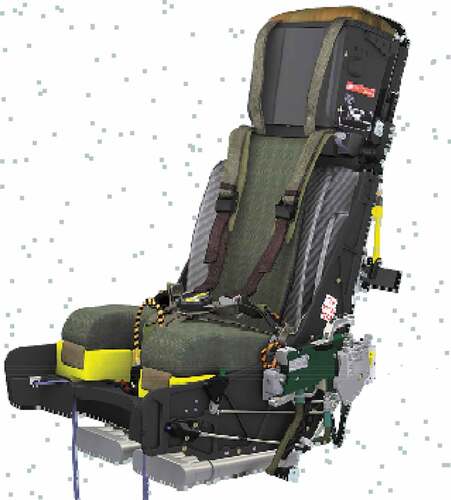
Figure 2. Various modes during seat ejection.
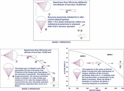
•Mode 1: Low altitude, low speed
The ejection of the pilot takes at speeds less than 250 knots and altitude of less than 15,000 feet. Drogue parachute does not deploy in Mode-I.
•Mode 2: Low altitude, high speed
The ejection of the pilot takes place at a speed of more than 250 knots and altitude less than 15,000 feet.
•Mode 3: High altitude, any speed
It is elected for any ejection at an altitude greater than 15,000 feet.
The sequence of various modes of seat-man combination during ejection is shown in
According to the IAM, Bengaluru, the maximum acceleration and rate of rise of “g” should not be greater than 25 “g” and 300 g/s (Patkar, Citation1974). Acceleration vs. time for physically permitted and design curve is shown in . The physically permitted curve is indicated in red colour, while the acceptable design curve is indicated with a green colour. If these limits are more than physiological limits, it will contribute to injury of the spinal cord of the pilot. From this figure, it is observed that the total time taken is divided into two phases. In phase I, acceleration increase steadily and reaches to the maximum value in time t1. In phaseII, acceleration is kept constant up to a stroke time ts.
Figure 3. Acceleration vs. time for physically permitted and the design curve.
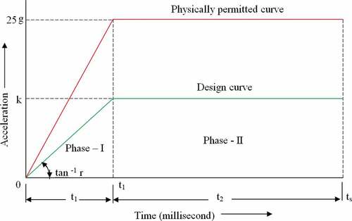
Phase-I is governed by the pressure generated by the primary cartridge, and phase-II is the sustenance of pressure by secondary cartridges after a certain time gap. An area under the acceleration–time profile indicates the velocity. The ejection velocity V is expressed as (Parate et al., Citation2021)
ts is the total time of operation
The acceleration a(t) gained during ejection is given by
k and r are constants, representing sustenance and the rate of rise of acceleration.
Integrating Equationequation (6)(6)
(6) using relation (7), it gives
Where t2 = ts - t1
Here, it is assumed that an ejection gun with a piston arrangement provides the required velocity to the seat-man combination.
Consider L1 and L2 are the stroke lengths (the distance covered by the piston in the gun tube) during the first and second time phases, respectively, it is given by
Therefore, the total stroke length of the piston is given by
Substituting for t1 and t2 from EquationEquation (9)(9)
(9) and (Equation10
(10)
(10) ) in EquationEquation (8)
(8)
(8) , the ejection velocity V, in terms of total stroke length, acceleration, and the rate of rise of acceleration, is given by
From the above equation, it is clear that, with the permissible values of k and r, higher velocity can obtained only by increasing the stroke length Ls.
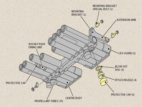
The modern fighter seat ejection is installed with explosive cartridges. They are installed on the main gun in the aircraft cockpit. The main gun is propelled by energy derived after propellant burning inside it. During an emergency, these cartridges are used to operate the main ejection system when the pilot pulls the firing handle situated between his thighs. The whole system is fully automatic once initiated by the pilot. As the sear is withdrawn from the firing mechanism, the pin strikes the cap. This generates the flash and ignites the primary cartridge. The resultant flash passes through the flash holes and ignites a booster composition. This subsequently ignites the propellant. The pressure developed inside the primary cartridge break the copper foil and releases the gas pressure. The telescopic tube gets expanded. The ports of the intermediate tube are uncovered due to the expansion of the telescopic tube. This is the only means to rescue the pilot in the emergency from the disabled aircraft within the shortest possible time. The principle of the telescopic gun is used for the ejection of the pilot. The system comprises the innermost tube, an intermediate tube and an external tube. This concept helps to avoid the requirement of a single tube considering the space constraint in the cockpit. The outermost tube is fitted to the aircraft structure. The various stages of the expansion of the telescopic tube with the total mass (pilot and seat) till the expansion of the full system are illustrated in . The actual position of the telescopic tube in the steady-state in the aircraft system is depicted at stage 1. The primary cartridge with a firing mechanism is fitted inside the innermost tube. The first primary cartridge is fired by the percussion firing mechanism. The expansion of an intermediate tube takes place due to a high temperature and pressure generated by the propellant burning inside the primary cartridge, as indicated at stage 2. The mass is lifted upward and secondary cartridges are fired as these cartridges are exposed to high pressure and temperature because of the port opening. This is shown at stage 3. At the end of the stroke, the pilot with an innermost tube is ejected out. This is shown at stage 4. During the seat ejection, the pilot will experience the force. Those forces are well within the permissible physiological limits. The idea behind the limitations is that the human body comprises a heterogeneous man with solid, liquid, and visco-elastic components. Each system has a different response to accelerative force and different systems will fail under the different loading conditions. The ejection velocity achieved using a telescopic tube is not sufficient to clear the aircraft’s tail fin. Therefore, rocket motor with multiple rocket units having a nozzle arrangement situated below the seat pan gives additional thrust for the safe escape of personnel from the disabled fighter aircraft in the shortest possible time. The rocket motor is illustrated in . The speed for the aircraft is 1,300 km/h, and the force experienced by the pilot is well within permissible physiological limits (acceleration 12–14 g).
Figure 4. Telescopic tube.
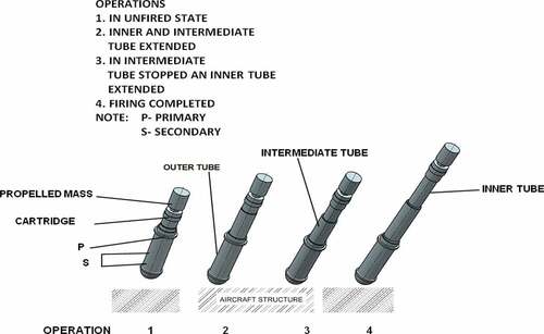
Figure 5. Rocket motor.
The latest research survey indicates the specification of a parameter known as dynamic response index (DRI) in place of the earlier specified limitations for the rate of change of acceleration, and maximum acceleration is used to determine the physiological limitations for crewman escape system. The average value of DRI is 18. It is a measure of human spine compression and pertinent to the pilot’s probability of injury and stress experienced during ejection. The DRI is expressed as (AMCP 706, Citation1975).
where and
are natural frequency of spinal column rad/s and maximum spinal compression.
6. Requirements of modern ejection seat
Considering today’s world scenario where the fighter aircraft are flying with supersonic speed of the order of Mach number either greater than two or three. To rescue the pilot from disabled aircraft with minimum possible time is essential to save his life. All aircraft shall incorporate with modern ejection seat and have the following requirements:
All the seats have a fully automatic escape system with high reliability and with minimum maintenance.
Stabilization gyros comprise a newly developed seat ejection to revoke asymmetric forces causing rotation and tumbling (David Reichena, Citation1972).
Drastic weight reduction in ejection seat with advanced use of materials. The materials having low density and durability are selected for weight reduction. These material technologies are used in light combat aircraft. Earlier conventional aircraft ejection seat had more weight (200 lb) than advanced aircraft seats (150 lb). With the advanced aircraft seat, its performance has improved through its entire flight envelope and reduction in drag. With this, the pilot experiences a maximum rate of rise of acceleration of 13.5 g−1 and maximum pressure of 30 MPa.
High structural strength to withstand crash loads and wind blast.
Modern seat should have maximum possible velocity over a given time frame.
Forces experienced by the pilot should be within physiological limits to avoid spinal cord injury.
Ejection seat must have the capability of wide range of altitude and speed during ground emergencies such as zero altitude and zero speed (Specker & Plaga, Citation1996). This technology uses the concept of a small rocket that ejects seat-man combination for sufficient height to deploy the parachute quickly. This is independent of altitude and airspeed. The pilots experience less force and hence minimize the chances of spinal injury.
Duplication of the system for high reliability.
Protection is given to the pilot against wind blast and other odd forces.
Survival pack and breathing oxygen systems are incorporated to the ejection seat.
ACES concept uses canopy breaking/shattering followed by the seat ejection. This is achieved by flexible linear shape charge (FLSC)/miniature detonating cord (MDC) embedded with stretched acrylic sheet.
Through canopy is achieved using spike breaker on the top seat ejection seat.
High technology helmet with night vision capability.
Drogue gun and drogue parachute deployment with seat adjustment unit.
Advanced ejection seat to provide occupant protection features and directional stability that extensively minimizes the risk of injury during ejection at high altitude.
Seat stabilization units are introduced to balance asymmetric forces generated due to tumbling and rotation.
Interconnected hand grips on either side of the ejection seat.
During an emergency, aeronaut has to abandon the military aircraft with the increase in the speed. Therefore, the FLSC technique having the capability to create the shock wave is used for this purpose. This phenomenon is generated in a millisecond. The loading density of FLSC varies from 0.8 to 100 g/m that depending upon the thickness of the sheet to be cut (Bement).
Modern ejection seat is equipped with recovery sequencer and environmental sensor behind the ejection seat using an onboard computer. The environmental sensor senses the airspeed and altitude of the seat. This data will be sent to the recovery sequencer. The pilot can select altitude and velocity. This gives him the best chance for survival in emergencies. The ejection sequence begins, the seat moves up the guide rails and exposes the pitot tube. It is designed to determine air pressure differences and air velocity. Information pertaining to the air velocity is sent to the sequencer that selected from three modes of ejections as explained in paragraph 5.
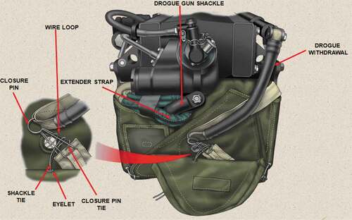
show the survival pack and the parachute pack. These are the essential components of modern seat ejection technology. Such types of advanced features are incorporated in ACES 5 that are being developed by Collins Aerospace.
Figure 6. Survival Pack.
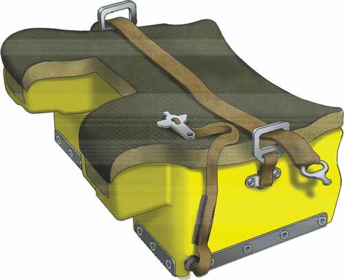
Figure 7. Parachute Pack.
7. Scope for future study
Taking into accounts, the field of aerodynamics and ballistics the ejection seats are designed and tested. show a telescopic and the rocket motor. Some aspects of further studies are listed below:
All modern fighter aircraft are equipped with digital technology, onboard computer, the rocket-assisted ejection guns made up of a telescopic guns replaced by conventional guns.
The increase in the cost of brass material is causing concern. The use of cheaper material, if found suitable, will reduce the cost. Possibilities of new material for cartridge cases are to be explored.
The physiological parameters, like acceleration, rate of rise of acceleration and velocity if exceeds may lead to fatal injury to the pilot. Hence, the measurement technique must be accurate, reproducible and accurate.
Use of advanced and controlled propulsion system so as to increase the impulse provided by propellant, thereby increasing the service life of propellant and ballistic properties.
The flow visualization and formation of wake around the seat when the pilot is ejected by using computational fluid dynamics and positive separation of occupant along with seat so as to avoid entanglement of any part of aircraft shall be studied by using high-speed photography.
8. Conclusions
Aerodynamic and dynamic aspects of the ejection system to bale out the pilot are explained along with all technical challenges. Wind tunnel testing is extremely useful for the analysis of the seat ejection mechanisms. This study helps to reduce the stabilization problems and correct the wind blast pressure on the pilot related high-speed ejection. Such type of analysis helps to reduce the cost, time, and conduct of experiments. There are some subjects on which little information is readily available. Despite of important advances in CFD analysis, the persistent efforts are needed to bring encouraging procedures and methods to full the growth and failure design applications. The current research is focused on high airspeed and high altitude to enhance the performance capability of future ejection seats.
With the expertise and technology available in the world, new technology of smart ejection development of ejection seats of advanced version in future that will meet the requirements of all services for fighter aircraft. The science and technology related to seat ejection in this manuscript are highlighted its significance in fulfilling the state-of-art techniques for the development of the smart seat. Author strongly feels that the efforts taken by scientists, engineers, researchers and technologists in this smart development of ejection seat are highlighted. Requirements of modern ejection seat are explained in paragraph 6. Author also covered some of the interesting and recently published frontline research papers.
Acknowledgements
The author would like to extend his gratitude for the kind permission granted by Dr. Venkateswara V Rao, Outstanding Scientist & Director ARDE, Pune to present this article. The author is grateful to the referee for their enlightening comments. The author also thank to officers/staff for their constant help extended directly or indirectly during finalization of this research work.
Disclosure statement
The author wish to confirm that there is no known conflict of interest regarding the publication of this paper. There has been no significant financial support for this work that could have influenced its outcome..
Additional information
Funding
Notes on contributors
B A Parate
Dr. B A Parate, is working at ARDE, Pune, and published several research articles in National and International Journals of repute. He obtained Ph.D. in Mechanical Engg from DIAT, Pune, in 2020. His doctoral research is based on ”Experimental and Analytical Analysis of Water-Jet Disruptor”. He is a member of various societies such as Aeronautical Society of India (AeSI) Pune, High Energy Material Society of India (HEMSI) Pune and Society of Aerospace Quality & Reliability (SAQR) Hyderabad.
He worked as a reviewer in various international peer-reviewed journals such as Defence Science Journal, Defence Technology, International Ballistic Symposium, and Journal of Modern Mechanical Engineering and Technology, etc. He is the recipient of ”Armament award” and ”Pinaka award”. He received a certificate and gold medal on the National Science day oration in 2021.
He has more than 23 years of experience in the armament field. His research interest includes the design, development and of various power cartridges for fighter aircraft.
References
- https://en.wikipedia.org/wiki/Ejection_seat
- https://aviationweek.com/defense-space
- Ejection seat KM-1M series 2 - Maintenance manual
- Ejection-history.org.uk. Archived from the original on 2010-11-22. Retrieved 2012-October-30.
- Eric Grundhauser: The story of ejection seat
- The history and developments of Martin-Baker escape systems
- KM-1M ejection seat - Technical description and operating instruction
- AMCP 706. (1975). Propellant Actuated Devices. Alexandria, Virginia
- Bement, L. J. Explosive fracturing of an f-16 canopy for through-canopy crew egress. NASA Langley Research Center, Presented at 38 th Annual SAFE Symposium, Reno, Nevada Oct 2000 9 20000109968
- Bogdan, & (2009). The research of ballistic properties of ejection seats rocket motors. Military University of Technology, Mechatronics Faculty, 2 Kaliski Str., 00-908 Warsaw, Poland, . 1–13.
- Brochure, M. Douglas Aerospace, Missouri, wikipedia https://en.wikipedia.org/wiki/Douglas_Aircraft_Company.
- Christopher, T. Carey a brief history of the development of western aircraft ejection seat systems https://www.academia.edu/11961151/A_BRIEF_HISTORY_OF_THE_DEVELOPMENT_OF_WESTERN_AIRCRAFT_EJECTION_SEAT_SYSTEMS
- Martin Baker site: https://fas.org/man/dod-101/sys/ac/equip/eject.htm dt. 28 Dec 2020.
- Parate, B. A. (2020). Propellant actuated device for parachute deployment during seat ejection for an aircraft application. High Tech and Innovation Journal, 1(3), 112–120. http://dx.doi.org/10.28991/HIJ-2020-01-03-03
- Parate, B. A., Deodhar, K. D., Dixit, V. K., & Rao, V. (2021). Ballistics of main seat ejection cartridges for aircraft application. International Conference on Ballistics, 17-18 May 2021 publications.waset.org/10012135/pdf Vol:15, No:7, 2021 (World Academy of Science, Engineering and Technology) Sydney Australia, Pt VI, 305–312 publications.waset.org/10012135/pdf
- Parate, B. A., Nair, P. K. S., & Namboodiri, A. V. (2001). Design of main ejection seat cartridges. Proceedings of National Workshop on Power Cartridges 05 Dec 2000 Maharashtra, Pune, 97–102
- Patkar, M. R. (1974). Ballistic of ejection seats. Proceeding of seminar on Nonlinear Ballistics Insitute of Adanced Technology (IAT), Khadakwasala, Pune (Pune, India), 241–260
- Reichena, D. E. A. (1972). Aerodynamic characteristics of an ejection seat escape system with a stabilization parachute at mach numbers from 0.3 through 1.2 Defence Technical Information Center
- Sławomir , STępień, & Stanisław , SzAjnA, Michał , jASzTAl (2017). problems of military aircraft crew’s safety in condition of enemy counteraction. eksploatacja i nieza- wodnosc, Science and Technology Maintenance and reliability 19 3 441–446 doi:http://dx.doi.org/10.17531/ein.2017.3.15.
- Specker, L. J., & Plaga, J. A. (1996 AL/CF-TR-1996-0099 (National Springfield, Virginia 22161: Technical Information Services)The K-36D Ejection Seat Foreign Comparative Testing (FCT.https://ia800105.us.archive.org).
- St Louis. (1993). ACES II Advanced Concept Ejection Seat, McDonnell Douglas Information
- Zygmunt, B., Motyl, K., & Surma, Z. (2008). Ballistic properties of propelling charges for ejection seats of modern aircrafts (in Polish), Biul. WAT, 57, 3, 97-110; VII, International Armament Conference, Pultusk 8-10.10.2008, 221–232.