
 ?Mathematical formulae have been encoded as MathML and are displayed in this HTML version using MathJax in order to improve their display. Uncheck the box to turn MathJax off. This feature requires Javascript. Click on a formula to zoom.
Abstract
Free space optics (FSO) systems use the atmosphere as a propagation medium. However, a common problem is atmospheric turbulence, including fog, rain, and haze that emerges between the transmitter and the receiver from time to time. These adverse weather conditions impose power loss on the optical signal, producing distortion and degrading bit error rate (BER) and throughput. To reduce the effect of atmospheric turbulence, this paper proposes a decision feedback equalizer (DFE) with minimum mean square error (MMSE) in mode division multiplexing (MDM) for the FSO system. The DFE with varying tap counts is investigated. The MMSE algorithm is utilized to optimize both the feedforward and feedback filter coefficients of the DFE. The proposed system consists of four parallel 2.5 Gbps channels that use Hermite-Gaussian (HG) modes. The results show that the DFE equalization scheme successfully transmits 10 Gbps over 40 m, 800 m, 1400 m, and 2 km in medium fog, medium rain, medium haze, and clear weather. Performance is analyzed in terms of BER and eye diagrams and compared with the traditional model. Based on BER and eye diagram results, DFE improves the outdoor FSO system immunity to distortion in medium fog, medium haze, medium rain, and clear weather while maintaining high throughput and desired low BER.
PUBLIC INTEREST STATEMENT
Free-Space Optical (FSO) Communication has fundamentally altered the way people communicate. It allows for efficient voice, video, and data transmission over a medium such as air as an alternative to wire communication systems. The primary benefits of FSO include high speed, cost savings, low power, energy efficiency, maximum transfer capacity, and applicability. However, atmospheric turbulence such as fog, rain, haze is one of the main problems that seriously limits the transmitted data rate in FSO systems. Atmospheric turbulence causes signal distortion during transmission that leads to data loss at the receiver side totally or partially. As a result, this study attempts to mitigate adverse effects of atmospheric turbulence, including clear weather, medium haze, medium rain, and medium fog during transmission of the data through the FSO link and increases the capacity of data transmitted and the distance under diverse atmospheric turbulence. Increasing the data rate transmitted through the FSO link enables the use of FSO in various applications essential to our daily lives.
1. Introduction
During the last ten years, the use of smartphones and apps has expanded rapidly, and the astonishing rise in the number of consumers making use of them worldwide is increasing daily. Consequently, demand for wireless network capacity has increased at an unprecedented rate (Singh, Atieh et al., Citation2021; Khalighi & Uysal, Citation2014). According to Cisco’s tenth annual report (Cisco, Citation2016), worldwide mobile data traffic was anticipated to rise eightfold between 2015 and 2020. leading to a need for greater bandwidth and high-speed transmission of data (Kaddoum, Citation2015). Because of numerous costs, security, noise, and bandwidth restrictions, the radio frequency (RF) spectrum can no longer meet the rising demand for bandwidth (Bashir et al., Citation2020; Bhatia et al., Citation2016; Nguyen et al., Citation2019; Singh, Atieh et al., Citation2021). Because it requires a license, RF is costly (Nguyen et al., Citation2019; Shah & Kothari, Citation2016). It is also insecure due to the possibility of snooping or interception (Nguyen et al., Citation2019; Shah & Kothari, Citation2016). The difficulty with interference in RF is that it generates noise in the signal (AlQuwaiee et al., Citation2016). Furthermore, the range of RF bandwidth is restricted to 10 Mbps to many hundred Mbps (Bashir et al., Citation2020; Bhatia et al., Citation2016).
Due to these RF restrictions, wireless communication industries are now shifting to an alternate approach that provides a significantly greater data rate and increased bandwidth (Bhatia et al., Citation2016; Chowdhury & Choyon, Citation2021a). The alternative option comes from FSO communication, which employs optical connections like lasers between sender and receiver to transfer data in unguided propagation through free space (Amphawan et al., Citation2017; Bhatia et al., Citation2016; Nguyen et al., Citation2019; Saraereh, Citation2021; Uysal & Uysal, Citation2014). When it comes to cost, safety, intervention, and bandwidth, FSO has numerous benefits over RF (Choyon & Chowdhury, Citation2020). It is inexpensive since it does not require a license and incurs minimal installation costs (Boobalan et al., Citation2021; Chowdhury & Choyon, Citation2021a; Choyon & Chowdhury, Citation2020; He et al., Citation2018; Nor et al., Citation2015; Shah & Kothari, Citation2016; Singh, Atieh et al., Citation2021). Given the difficulties of eavesdropping or intercepting the optical signal, FSO is more secure, making it more suitable for use in the military, financial, and banking sectors (Bhatia et al., Citation2016; Boobalan et al., Citation2021; Nor et al., Citation2015). FSO ensures little or no interference between optical frequencies (Bhatia et al., Citation2016; Saraereh, Citation2021). Furthermore, because the frequency of the optical carriers is between 1012 and 1016 Hz, FSO has a significant data bandwidth reach of up to 2000 THz and a data rate of 10 Gbps (Bhatia et al., Citation2016).
FSO also provides increased capacity through the use of mode division multiplexing (MDM) technology. MDM is a contemporary technique used to transfer optical signals or light beams in modes across transmission channels while increasing capacity (Amphawan & Chaudharya, Citation2015; Li et al., Citation2014). Various orthogonal overlapping spatial modes are used to transmit multiple data streams in MDM (Singh, Atieh et al., Citation2021). This increases data transmission capability, and overall spectrum efficiency by a factor equal to the number of spatial modes used (Singh, Atieh et al., Citation2021). This technology has been successfully deployed across fiber optics and FSO to improve data capacity. As a consequence of these characteristics, FSO is regarded as one of the critical technologies attracting the future generation of wireless networks and broadband communication (Balasaraswathi et al., Citation2020; Boobalan et al., Citation2021; Majumdar, Citation2015; Saraereh, Citation2021). However, the major issue affecting FSO systems’ performance is atmospheric turbulence, which causes signal distortion (Boobalan et al., Citation2021; Goyal et al., Citation2015; Magidi & Jabeena, Citation2021; Nguyen et al., Citation2019; Saraereh, Citation2021; Singh, Atieh et al., Citation2021; R. Wang et al., Citation2019).
Numerous equalization techniques have been suggested for free-space transmission to reduce signal distortion. Adaptive equalization based on recursive least squares (RLS) was introduced in (Y. Wang et al., Citation2015) to eliminate inter-symbol interference (ISI) and enhance the performance of a visible light communication (VLC) system using wavelength division multiplexing (WDM). Using RLS enhanced the performance of the WDM VLC system, allowing up to 4.5 Gbps to be transmitted across a 1.5 m distance to an indoor FSO with a bit error rate (BER limit) of 3.8 × 10⁻³. According to the authors of (Bekkali et al., Citation2010), the performance of maximum likelihood sequence estimation (MLSE) equalizers is frequently not met in turbulent environments due to their sensitivity to each parameter in the transversal structure. The whole equalizer deteriorates in the case of failure; any parameter holds the desired value. The suggested orthogonal frequency division modulation (OFDM) technique is used to simplify the equalization task. Experiments comparing OFDM and FSO claim that the results might help FSO design and evaluate its ability to transfer data across turbulent connections under experimental settings. In (Tapse et al., Citation20112011), an analytical model for transmitting signals depending on OFDM through FSO connections is provided, taking optical signal noise and non-linear disruption into account for the laser source. The influence of atmospheric turbulence was modelled using a gamma-gamma distribution. The findings demonstrated an essential improvement in the performance of BER using this technique, which might help design networks depending on OFDM for transmission of data and removing the ISI. As a result of the complicated calculations for the channel estimation algorithm based on MMSE and used over the OFDM-FSO system, singular value decomposition (SVD) based on MMSE was proposed in (Zhao & Li, Citation2011) to overcome complicated calculations for MMSE over OFDM-FSO. The SVD-MMSE decreased the complicated these calculations and ensure reliability. In (S. Malik & Sahu, Citation2020), RF/FSO system was proposed for terrestrial application. The simulation results showed that high path loss under various weather circumstances, most notably clouds, fog, and rain, affects the data rate and received signal strength in vertical and horizontal RF/FSO connections. In (Balasaraswathi et al., Citation2020), the radio over FSO (RoFSO) link with WDM/MDM was proposed and tested in heavy fog. The results indicated an increase in link range and transmission capacity. However, the focus was only on heavy fog. In (Chowdhury & Choyon, Citation2021a), an FSO communication system hybridizing circular polarization division multiplexing (CPDM) with coherent optical OFDM was proposed and investigated under diverse turbulent weather conditions (rain and fog). The outcomes showed good performance by maximizing the FSO system’s link capacity and enhancing the system’s spectral efficiency. In (Chowdhury & Choyon, Citation2021b), an alternate mark inversion (AMI)-encoded FSO system was proposed, hybridizing polarization division multiplexing (PDM) with WDM, and its performance was investigated under diverse weather conditions (clear, haze, and rain). The results indicated that the PDM-WDM technique maximizes the link capacity of the FSO system and enhances the system’s spectral efficiency. In (Choyon & Chowdhury, Citation2021), a 16 × 40 Gbps hybrid PDM-WDM FSO system was designed, and its performance was investigated under various turbulent weather conditions (rain and fog). The outcome demonstrated that the PDM-WDM technique maximizes the link capacity of the FSO system and enhances the system’s spectral efficiency.
That is, various equalization techniques based on different algorithms such as RLS, MMSE, and SVD-MMSE, have been used to reduce the effects of atmospheric turbulence on a signal transmitted over FSO. The equalization algorithms have been applied in various configurations of FSO, most significantly based on OFDM and WDM. The application of equalization to these multi-channel systems in FSO has been shown to improve BER.
While MDM has been used to increase capacity and distance over FSO, equalization has not been used to optimize MDM performance in FSO (Goyal et al., Citation2015). In (Milione et al., Citation2015), MDM over FSO achieved an 80 Gbps transmission rate over a 1 m distance. Using space-division multiplexing (SDM), 280 Gbps was transmitted across a distance of 5 m in (Avery et al., Citation2016). In (Amphawan & Chaudharya, Citation2015), (Amphawan, Chaudhary, Neo et al., Citation2015), and (Amphawan, Chaudhary, Din et al., Citation2015), MDM for FSO was achieved by transferring 5 Gbps for distances of 400 m, 500 m, and 800 m, respectively, under clear weather conditions. In (Boobalan et al., Citation2021), three × 20 Gbit/s optical OFDM using MDM of three spiral phased Hermite Gaussian (HG) modes were successfully transmitted in different rain weather conditions (light rain, moderate rain, and heavy rain). In (Singh, Pottoo, Dewra et al., Citation2021), a 2 × 10 Gb/s-10 GHz RoFSO transmission system using MDM was designed to transmit the data through varying levels of dust weather conditions. The results showed a reliable transmission of 20 Gb/s-20 GHz data through two HG channels over a link range of 2500–108 m depending on the external dust condition. In (Singh, Chebaane et al., Citation2021), an FSO link was proposed for transmission of 4 × 20 Gbps data over an OFDM-based FSO link by incorporating hybrid WDM and MDM techniques under different atmospheric conditions. In (Singh, Pottoo et al., Citation2021), a design of OFDM-MDM based radio over the RoFSO transceiver under the dust effect was proposed. Two separate 20 Gbps-40 GHz 4-QAM data-bearing optical beams were transported over two distinctive HG modes of a single-frequency laser to realize a single-channel 40 Gbps-80 GHz 5 G communication link. In (Singh, Pottoo, Aly et al., Citation2021), a hybrid WDM-MDM-based RoFSO communication system was designed with four distinct spatial laser HG modes through four independent channels (850–852.4 nm). The results demonstrated the successful transmission of a 160-Gb/s information signal in a harsh dust environment. In (Sharma et al., Citation2021), the MDM technique was proposed to provide a more cost-effective solution and immunity to various losses. Two channels, each having a unique mode, was used to carry data at 10 Gbps on an inter-satellite optical wireless communication (Is-OWC) network. Only one study (Almogahed et al., Citation2017) investigated the impact of atmospheric turbulence for MDM over FSO, where a data rate of 7.5 Gbit/s was achieved. To the best of our knowledge, there is a lack of studies investigating the effect of atmospheric turbulence on MDM over FSO.
We have therefore proposed using a decision feedback equalizer (DFE) in the MDM FSO system to reduce atmospheric turbulence. The remainder of the paper is organized in the following manner. Section 2 explains the proposed system. The results are discussed in Section 3. Performance improvement from the proposed system is described in Section 4. The conclusion and future work are presented in Section 5.
2. System design
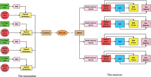
depicts the block diagram of the proposed DFE in the MDM-FSO model utilizing OptSim 5.2 software. At the transmitter side, the proposed design is composed of four separate non-return-to-zero (NRZ) encoded channels, each transmitting a 2.5 Gbps data stream via an 850 nm optical spatial carrier. Four Hermite Gaussian (HG) laser modes are utilized for data transmission. Channel 1 has HG 0,0, Channel 2 HG 0,1, Channel 3 HG 0,2, and Channel 4 HG 1,0. Under medium fog, medium rain, medium haze, and clear weather circumstances, the output of the four channels is combined and broadcast over distances of 40 m, 800 m, 1400 m, and 2 km of free space. The HG modes can be mathematically described using ; Amphawan & Chaudharya, Citation2015; Boobalan et al., Citation2021; Singh, Chebaane et al., Citation2021):
Where r is the dependency of mode profile on the X-axis, s is the dependency of mode profile on the Y-axis, the beam’s radius is denoted by R, ω0 denotes the size of the optical beam at the waist, and Hm and Hn denote Hermite polynomials. Different HG modes are excited using a spatial laser. The output of the four channels is combined, amplified and transmitted through free space at distances ranging from 40 m to 2000 m.
The free space optics connection equation is represented in ; Refai et al., Citation2005):
The output mode is sent to a spatial photodetector to reduce atmospheric turbulence, which DFE subsequently follows. dR denotes the receiver aperture diameter; the transmitter aperture diameter is denoted by dT, the beam divergence by θ, the range by R, and the atmospheric attenuation by α. An optical splitter extracts the transferred mode at the receiver. To assess the performance of the MDM FSO system prior to and following the DFE scheme, a BER tester and an eye-diagram analyzer are utilized.
Figure 1. DFE block diagram of MDM for FSO.
lists the simulation parameters.
Table 1. DFE simulation parameters in MDM for the FSO system (Almogahed et al., Citation2017; Amphawan et al., Citation2015; Amphawan & Chaudharya, Citation2015)
Attenuation is regarded as one of the primary parameters reducing FSO systems’ performance. Attenuation decreases the power of the signal at the receiver. Typically, attenuation levels fluctuate in response to changes in atmospheric conditions. depicts the attenuation values for various weather conditions (A. Malik & Singh, Citation2015).
Table 2. Attenuation values for different weather conditions (Almogahed et al., Citation2017; A. Malik & Singh, Citation2015)
2.1. Optimizing the DFE Taps Using the MMSE Algorithm
To reduce the mean square error (MSE), both the feedforward filter (FFF) and the feedback filter (FBF) taps of DFE are optimized using the MMSE algorithm (Sur et al., Citation2015). The simplest technique for determining the optimal taps is to tackle a problem with the sole objective of obtaining the best signal (Stephens, Citation2005). This will be accomplished by selecting taps with the lowest difference between equalized and transmitted (or ideal) signals (Almogahed et al., Citation2017; Stephens, Citation2005). depicts the MMSE-DFE structure.
Figure 2. MMSE-DFE block diagram.
From (Al-Dhahir & Cioffi, Citation1995) and (Voois et al., Citation1996), the overall input/output relationship of the channel is as shown in ; Al-Dhahir & Cioffi, Citation1995; Voois et al., Citation1996):
Where yk represents the channel’s output, hi the channel’s pulse response, xi the channel’s input, nk the noise sequence, k the estimated time, and v the channel’s memory. DFE filters are vectorial and have finite lengths. The FFF is made up of an Nf taps vector represented by w, where (Voois et al., Citation1996):
Moreover, FBF is made up of an Nb taps vector represented by b, where (Voois et al., Citation1996):
Our objective is to select w and b to optimize the performance of the MMSE-DFE based on a performance criterion. MSE is used as our performance metric. From , the error sequence, ek, is given by (Al-Dhahir & Cioffi, Citation1995):
Where Zk denotes the decision latency and is the output of FFF; as a result, MSE is provided by (Al-Dhahir & Cioffi, Citation1995):
We define Rxx and Rnn as the autocorrelation matrices of the channel input and noise sequences, respectively, and H as the Toeplitz channel coefficients matrix (Al-Dhahir & Cioffi, Citation1995).
Then Equationequation (5)(5)
(5) becomes (Al-Dhahir & Cioffi, Citation1995):
In order to reduce the MSE, we utilize (Al-Dhahir & Cioffi, Citation1995):
Moreover, combining Equationequations (9)(9)
(9) and (Equation10
(10)
(10) ), we get (Al-Dhahir & Cioffi, Citation1995):
Where (Al-Dhahir & Cioffi, Citation1995):
The matrix inversion lemma’ is followed by the last line (assuming that Rxx and Rnn are invertible). By specifying (Al-Dhahir & Cioffi, Citation1995):
EquationEquation (11)(11)
(11) becomes (Al-Dhahir & Cioffi, Citation1995):
This is a non-linear pattern that has been reduced using the FBF settings listed below (Al-Dhahir & Cioffi, Citation1995):
As a result, the MMSE is (Al-Dhahir & Cioffi, Citation1995):
The optimal FFF w*opt was computed as follows using Voois et al., Citation1996):
Obtaining the best DFE performance depends on how many FFF and FBF taps were used to reclaim the source signal. The possible number of FFF taps in OptSim 5.2 is between 1 and 100, while the number of FBF taps that can be used is between 0 and 100. Choosing the appropriate number of FFF and FBF taps to get the best performance in our experiments relies on the trial-and-error method. Trial and error are defined as a series of repeated, varied attempts that are carried out until success is achieved.
2.2. Feedforward Equalizer (FFE) versus Decision Feedback Equalizer (DFE)
The feedforward equalizer (FFE) is a linear equalizer that uses previously received bits (Almogahed et al., Citation2017). It forwards data from previous bits to the following bits. For various reasons, the FFE is unable to eliminate all ISI. The FFF is discrete, with one tap used per bit, whereas the ISI is continuous. Because the FFF is limited, it cannot completely correct the impulse response. Furthermore, it only uses data from the current and previous bits, resulting in noise gain (Almogahed et al., Citation2017).
The DFE is a non-linear equalizer that compensates for the shortcomings of the FFE (Almogahed et al., Citation2017). A delay is introduced in DFE so that both pre-and post-cursors can be used in the additional correction, which uses the logical decision of the last bits as feedback to improve the equalization process (Al-Dhahir & Cioffi, Citation1995; Voois et al., Citation1996). DFE adds FBF taps to the decoded digital signal and typically includes a delay between the FFE and the feedback loop (Al-Dhahir & Cioffi, Citation1995; Voois et al., Citation1996). The idea is that the FFE can only correct the ISI that spreads across its cursors; the logic-based feedback loop can correct the remaining ISI (Al-Dhahir & Cioffi, Citation1995; Almogahed et al., Citation2017; Voois et al., Citation1996).
3. Results and discussion
The effectiveness of DFE in MDM over the FSO will be assessed using BER and an eye diagram for a distance under four different weather conditions. In sub-sections 3.1, 3.2, 3.3, and 3.4, results from the simulations are presented and discussed.
3.1. Clear weather condition
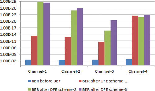
Under clear weather circumstances, the FSO connection can successfully transmit 10 Gbps of data over a distance of 2 km. In clear weather, the attenuation value is 0.155 dB/km. FFF and FBF taps for DFE were modified three times to explore and achieve optimum performance. The BER for each channel is shown in before and after the various DFE schemes.
Table 3. BER in clear weather prior to and following the various DFE schemes
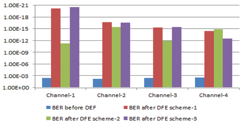
depicts a comparison of the BER of each channel prior to and following DFE using various DFE schemes.
Figure 3. BER comparison for every channel prior to the DFE and after various DFE schemes in clear weather.
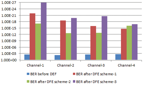
It is observed that, as illustrated in and , increasing the number of DFE taps reduces the BER. DEFs with four FFF and one FBF taps performed better than others. illustrates the values of taps and delay for each DFE from MMSE optimization, in the case where several FFF taps is four, and the number of FBF taps is one.
Table 4. DFEs taps coefficients from MMSE optimization in the case of four FFF taps and one FBF tap
The received bits enter the four FFF taps. Each tap is applied to the voltage level to correct it, and passes information from the last bits to the following bits. The equalized signal is generated by multiplying the ideal coefficient value from MMSE for each tap, as indicated in , by the voltage level of the received bit. However, because each FFF tap corrects one bit, the four FFF taps cannot correct all distortion. As a result, the outcome of four FFF taps is added to the feedback loop and logic decision to achieve an extra correction. The remaining distortion is corrected by multiplying the optimum coefficient value for this tap from MMSE, as indicated in , by the voltage level of the received bit. To create the equalized signal, the output of the one FBF tap is added to the output of the four FFF taps. Using this procedure for the three distinct DFE schemes makes it clear that increasing the number of taps allows the system to eliminate more distortion.
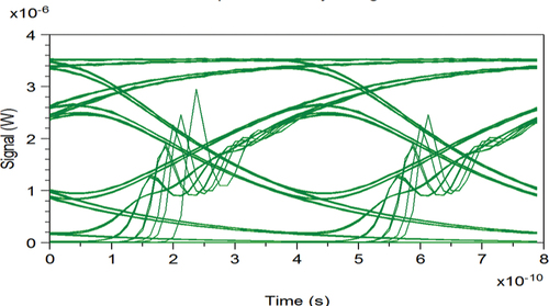
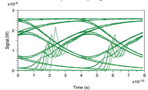
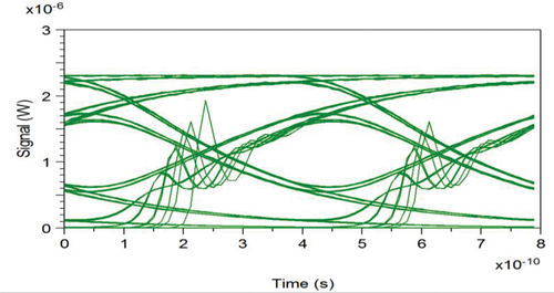
depicts the eye diagram at the transmitter after the FSO channel reflects that the signal has much distortion.
Figure 4. Eye diagram at transmitter in the case of clear weather.
depicts the receiver’s eye diagram for every channel prior to and following DFE, assuming four FFF taps and one FBF tap. After DFE, clear and broad eye diagrams indicate that 10 Gbps data was successfully transmitted over a distance of 2 km with an appropriate signal to noise ratio (SNR).
Table 5. Eye diagram for every channel prior to and following DFE in the case of four FFF taps and one FBF tap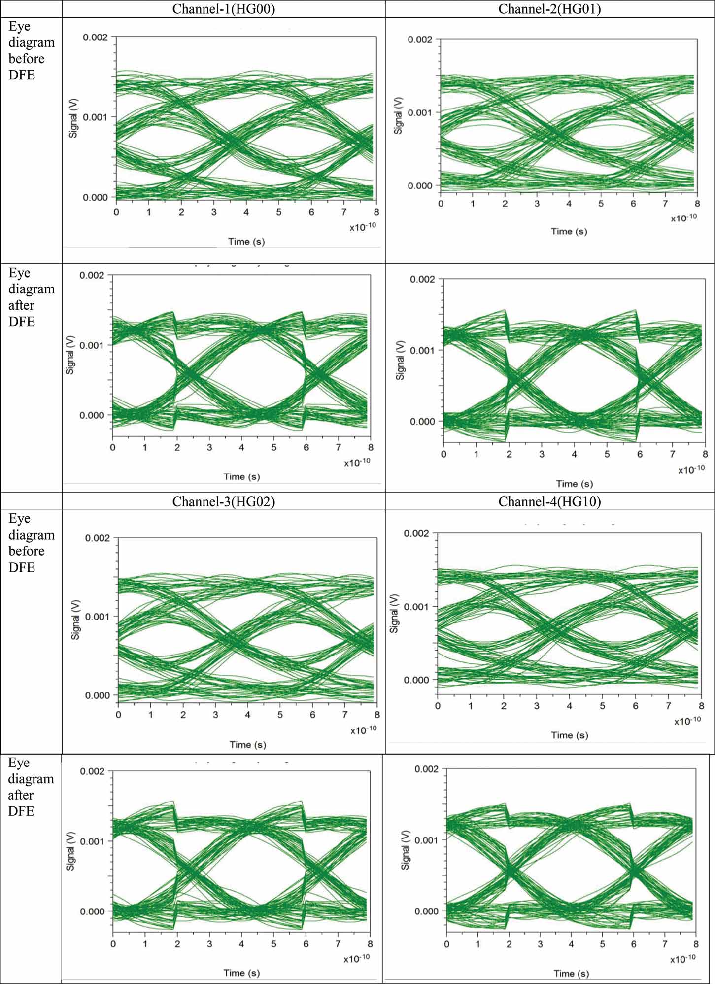
3.2. Medium Haze Weather Condition
The attenuation value in the medium haze is 4.285 dB/km. Through the FSO link, 10 Gbps of data transmission can indeed be accomplished over a distance of 1400 m in medium haze. Several FFF and FBF taps for DFE have been altered three times to examine and achieve the best performance. The BER for every channel is shown in prior to and following various DFE schemes.;
Table 6. BER prior to and following the various DFE schemes in medium haze
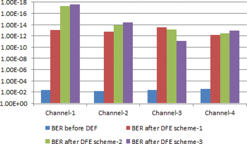
The comparison of the BER for every channel prior to and following various DFE schemes is shown in .
Figure 5. BER comparison for every channel prior to the DFE and after various DFE schemes in medium haze.
It is observed that, as illustrated in and , increasing the number of DFE taps reduces the BER. DEFs with three FFF and six FBF taps outperformed the others. illustrates the values of taps and delay for each DFE from MMSE optimization in the case where several FFF taps is three and the number of FBF taps is six.
Table 7. DFEs taps coefficients from MMSE optimization in the case of 11 FFF taps and three FBF taps
The received bits enter the three FFF taps. Each tap is applied to the voltage level to correct it and passes information from the last bits to the following bits. The equalized signal is generated by multiplying the optimum coefficient value from MMSE for each tap, as indicated in , by the voltage level of the received bit. However, because each FFF tap corrects one bit, the three FFF taps cannot correct all distortion. As a result, to achieve an additional correction, the outcome of three FFF taps adds to a logic decision and feedback loop. The remaining distortion is corrected by multiplying the optimum coefficient value for each tap from MMSE, as indicated in , by the voltage level of the received bit. To create the equalized signal, the output of the six FBF taps is added to the output of the three FFF taps. By utilizing this procedure on three different DFE schemes, it is clear that increasing the number of taps allows the system to remove more distortion.
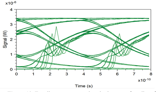
The eye diagram at the transmitter is shown in after the FSO channel reflects the signal’s high distortion.
Figure 6. Eye diagram at transmitter in the case of medium haze.
illustrates the receiver’s eye diagram for every channel prior to and following DFE, assuming three FFF taps and six FBF taps. Following DFE, clear and wide eye diagrams show effective transmission of 10 Gbps data with appropriate SNR across a distance of 1400 m in medium haze.
Table 8. Eye diagram for every channel prior to and following DFE in the case of three FFF taps and six FBF taps
3.3. Medium Rain Weather Condition
The FSO link can successfully transmit data at 10 Gbps over a distance of 800 m in medium rain. Medium rain has an attenuation value of 9.64 dB/km. Several FFF and FBF taps for DFE were altered three times to examine and optimize performance. The BER for every channel is shown in prior to and following various DFE schemes.
Table 9. BER prior to and following the various dfe schemes in medium rain
depicts a comparison of BER for every channel prior to DFE and after various DFE schemes.
Figure 7. BER comparison for every channel prior to the DFE and after various DFE schemes in medium rain.
As illustrated in and , increasing the number of DFE taps reduces the BER. DEFs with seven FFF and four FBF taps outperformed others. illustrates the values of the taps and delay for each DFE from MMSE optimization in the case where several FFF taps is seven, and the number of FBF taps is four.
Table 10. DFEs taps coefficients from MMSE optimization in the case of seven FFF taps and four FBF taps
The received bits enter the seven FFF taps. Each tap is applied to a bit’s voltage level to correct it and passes information from the last bits to the next bits. The equalized signal is generated by multiplying the optimal coefficient value for each tap from MMSE, as shown in , by the received bit’s voltage level. However, because each FFF tap can only correct one bit, the seven FFF taps cannot correct all distortion. As a result, the yield of seven FFF taps has been added to a logic decision and feedback loop. The remaining distortion is corrected by multiplying the optimal coefficient value for each tap from MMSE, as illustrated in , by the voltage level of the received bit. To produce the equalized signal, the output of the four FBF taps is added to the output of the seven FFF taps. Applying this procedure to the three DFE schemes demonstrates that increasing the number of taps enables the system to cancel out more distortion.
The eye diagram at the transmitter is shown in after the FSO channel reflects the signal’s high distortion.
Figure 8. Eye diagram at transmitter in the case of medium rain.
depicts the receiver’s eye diagram for every channel before and after the DFE when seven FFF taps and four FBF taps are supposed. After DFE, clear and wide eye diagrams show successful transmission of 10 Gbps data with appropriate SNR over a distance of 800 m in medium rain.
Table 11. Eye diagram for every channel prior to and following DFE in the case of seven FFF taps and four FBF taps
3.4. Medium Fog Weather Condition
Medium fog has an attenuation value of 33.961 dB/km. Compared to other weather conditions, the medium fog state has the highest attenuation factor for laser beams in the atmosphere. In general, it reduces visibility and has an impact on FSO performance. In medium fog, the FSO link can successfully transmit 10 Gbps of data across a distance of 40 m. Several FFF and FBF taps for DFE have been altered three times to explore and achieve the optimum performance. shows the BER for every channel prior to and following various DFE schemes.
Table 12. BER prior to and following the various DFE schemes in medium fog
The comparison of the BER for every channel prior to and following various DFE schemes is shown in .
Figure 9. BER comparison for every channel prior to and following various DFE schemes in medium fog.
As indicated in and , raising the number of DFE taps reduces the BER. DEFs with five FFF and five FBF taps performed better than others. shows the tap and delay values from MMSE optimization for each DFE in the case of many FFF taps, and where the number of FBF taps is five.
Table 13. DFEs taps coefficients from MMSE optimization in the case of five FFF taps and five FBF taps
The received bits enter the five FFF taps. Each tap is applied to a bit’s voltage level to fix it and passes information from the last bits to the following bits. The equalized signal is generated by multiplying the optimum coefficient value for each tap from MMSE by the voltage level of the received bit, as shown in . However, because each FFF tap corrects one bit, the five FFF taps cannot correct all distortion. As a result, five FFF taps have been added to the logic decision and feedback loop to achieve an extra correction. The remaining distortion is corrected by multiplying the optimum coefficient value for each tap from MMSE, as indicated in , by the voltage level of the received bit. To create the equalized signal, the output of the five FBF taps is added to the output of the five FFF taps. Using this procedure on the three distinct DFE schemes makes it clear that increasing the number of taps allows the system to eliminate more distortion.
The eye diagram at the transmitter is shown in after the FSO channel has reflected the signal’s significant distortion.
Figure 10. Eye diagram at transmitter in the case of medium fog.
depicts the eye diagram at the receiver prior to and following DFE if there are five FFF taps and five FBF taps. Following DFE, clear and wide eye diagrams effectively transmit 10 Gbps data with appropriate SNR across 40 m in medium fog.
Table 14. The eye diagram for every channel prior to and following DFE in the case of five FFF taps and five FBF taps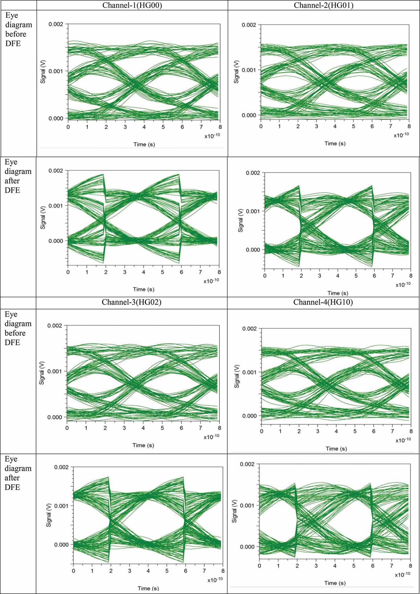
4. Comparison of the DFE Scheme in MDM for FSO System with Previous MDM-FSO Systems
To evaluate the performance of the DFE equalization scheme, it is necessary to compare the DFE equalization in MDM for FSO with previous systems; the MDM FSO system in (Amphawan, Chaudhary, Neo et al., Citation2015) has been used in clear weather conditions. shows the comparison between the proposed and previous systems. The goal of the comparison is to show that the DFE equalization scheme can improve the performance of the MDM FSO system.
Table 15. Comparison performance of the DFE scheme in MDM for FSO system with previous MDM-FSO system
Previous MDM-FSO has confirmed successful data transmission of 2.5Gbps over an FSO link of 600 meters for Channel 1, and 2.5Gbps for 400 meters for Channel 2, under clear weather conditions. In the DFE scheme in MDM-FSO, each channel confirms successful data transmission of 2.5Gbps over an FSO link of 2 km under clear weather conditions. The results of this comparison confirm that the successful DFE scheme improves MDM-FSO by increasing the data rate and distance.
5. Conclusions and future work
In this paper, simulation modelling of a DFE in MDM for the FSO system has been investigated, utilizing OptSim 5.2 software. Atmospheric turbulence has shown that the FSO performance was influenced very much by the medium fog, medium rain, and haze conditions, where BER values range between 2.1656 × 10⁻³ and 5.3868 × 10⁻³. We have demonstrated that introducing a DFE can effectively mitigate the effect of atmospheric turbulence, thereby improving BER performance, where BER values range between 2.0276 × 10⁻¹¹ and 4.3233 × 10⁻²⁹. In this work, we have found that communication links of 40 m, 800 m, 1400 m, and 2 km with 10 Gbps data transmission are successfully transmitted through the MDM-FSO system under medium fog, medium rain, medium haze, and clear weather conditions respectively. Further research can be conducted to increase the rate of data transferred long-distance through an MDM-FSO link under diverse atmosphere turbulence by incorporating other equalization schemes such as a dynamic evolving neural fuzzy inference system and electrical feedback equalizers. The proposed link can be realized in practice by further experiments.
Disclosure statement
No potential conflict of interest was reported by the author(s).
Additional information
Funding
Notes on contributors
Abdullah Almogahed
Abdullah Almogahed holds a bachelor’s degree in Engineering and Information Technology, with a major in software engineering, from Taiz University, Yemen, in 2009. He received his Master of Science in Information Technology from Universiti Utara Malaysia, Malaysia, in 2017. He pursued his PhD in Computer Science from Universiti Utara Malaysia in 2021. Since 2010, he has been a lecturer at the Faculty of Engineering and Information Technology, Taiz University, Yemen. He has published several publications in Scopus, indexed journals, and conference proceedings. His current research interests are wireless optical communications, free-space optical communication systems, equalization techniques, software refactoring, and software quality.
References
- Al-Dhahir, N., & Cioffi, J. M. (1995). MMSE decision-feedback equalizers: Finite-length results. IEEE Transactions on Information Theory, 41(4), 961–25. https://doi.org/10.1109/18.391242
- Almogahed, A., Amphawan, A., & Fazea, Y. (2017). Mitigation of atmospheric turbulences using mode division multiplexing based on decision feedback equalizer for free space optics. Journal of Optical Communications, 41(2), 185–193. https://doi.org/10.1515/joc-2017-0169
- AlQuwaiee, H., Ansari, I., & Alouini, M.-S. (2016). On the Maximum and Minimum of Double Generalized Gamma Variates with Applications to the Performance of Free-space Optical Communication Systems. IEEE Transactions on Vehicular Technology, 651, 1. http://doi.org/10.1109/TVT.2016.2515662
- Amphawan, A., Chaudhary, S., Din, R., & Omar, M. N., (2015). 5Gbps HG 0, 1 and HG 0,3 Optical Mode Division Multiplexing for RoFSO,” in IEEE International Colloquium on Signal Processing and its Applications (CSPA), Kuala Lumpur, Malaysia, Kuala Lumpur: IEEE.
- Amphawan, A., Chaudhary, S., & Neo, T. (2015). Hermite-Gaussian Mode Division Multiplexing for Free-Space Optical Interconnects. Advanced Science Letters, 21(10), 3050–3053. https://doi.org/10.1166/asl.2015.6532
- Amphawan, A., & Chaudharya, S., (2015). Free-space optical mode division multiplexing for switching between millimeter-wave picocells. Presented at the International Conference on Optical and Photonic Engineering. Singapore: SPIE.
- Amphawan, A., Ghazi, A., & Al-dawoodi, A. (2017). Free-space optics mode-wavelength division multiplexing system using LG modes based on decision feedback equalization. In EPJ Web of Conferences, Avillion Port Dickson, Malaysia (Vol. 162, p. 01009). EDP Sciences.
- Avery, M. A. P. J. L., Uang, H. A. O. H., En, Y. O. R., Ie, G. U. X., & Willner, A. E. (2016). Demonstration of a 280 Gbit/s free-space space-division-multiplexing communications link utilizing plane-wave spatial multiplexing. Optics Letters, 41(5), 851–854. https://doi.org/10.1364/OL.41.000851
- Balasaraswathi, M., Singh, M., Malhotra, J., & Dhasarathan, V. (2020). A high-speed radio-over-free-space optics link using wavelength division multiplexing-mode division multiplexing-multibeam technique. Computers & Electrical Engineering, 87(Octobar), 106779. https://doi.org/10.1016/j.compeleceng.2020.106779
- Bashir, S., Alsharif, M. H., Khan, I., Albreem, M. A., Sali, A., Ali, B. M., & Noh, W. (2020). MIMO-Terahertz in 6G Nano-Communications: Channel Modeling and Analysis. CMC-Computers Materials & Continua, 66(1), 263–274. https://doi.org/10.32604/cmc.2020.012404
- Bekkali, A., Ben Naila, C., Kazaura, K., Wakamori, K., & Matsumoto, M. (2010). Transmission Analysis of OFDM-Based Wireless Services Over Turbulent Radio-on-FSO Links Modeled by Gamma-Gamma Distribution. IEEE Photonics Journal, 2(3), 510–520. https://doi.org/10.1109/JPHOT.2010.2050306
- Bhatia, S., Singh, M., & Kaushal, H., (2016). Performance Analysis in Free Space Optical Communication System Using Aperture Averaging. Proceedings of the Second International Conference on Computer and Communication Technologies, New Delhi, Sproinger, pp. 319–327.
- Boobalan, S., Prakash, S. A., Angurala, M., Malhotra, J., & Singh, M. (2021). Performance Enhancement of 3× 20 Gbit/s MDM-Based OFDM-FSO System. Wireless Personal Communications, 122 February 2022, 1–29. https://doi.org/10.1007/s11277-021-09044-4
- Chowdhury, R., & Choyon, A. S. J. (2021a). Design and performance analysis of spectral-efficient hybrid CPDM-CO-OFDM FSO communication system under diverse weather conditions. Journal of Optical Communications. https://doi.org/10.1515/joc-2021-0113
- Chowdhury, R., & Choyon, A. S. J. (2021b). Design of 320 Gbps hybrid AMI-PDM-WDM FSO link and its performance comparison with traditional models under diverse weather conditions. Journal of Optical Communications. https://doi.org/10.1515/joc-2020-0135
- Choyon, A. S. J., & Chowdhury, R. (2020). Performance comparison of free-space optical (FSO) communication link under OOK, BPSK, DPSK, QPSK and 8-PSK modulation formats in the presence of strong atmospheric turbulence. Journal of Optical Communications. https://doi.org/10.1515/joc-2019-0250
- Choyon, A. S. J., & Chowdhury, R. (2021). Design of 16× 40 Gbps hybrid PDM-WDM FSO communication system and its performance comparison with the traditional model under diverse weather conditions of Bangladesh. Journal of Optical Communications. https://doi.org/10.1515/joc-2020-0247
- Cisco. (February 3, 2016). 10th Annual Cisco Visual Networking Index (VNI) Mobile Forecast Projects 70 Percent of Global Population Will Be Mobile Users. https://newsroom.cisco.com/press-release-content?articleId=1741352
- Goyal, P., Kumar, A., & Nath, V., (2015). Mitigation of Atmospheric Turbulence in Free Space Optics: A Review. Presented at the 2015 Fifth International Conference on Advanced Computing & Communication Technologies, Haryana, India, IEEE.
- He, X., Zhao, X., Cui, S., & Gu, H. (2018). A rapid hybrid wave front correction algorithm for sensor-less adaptive optics in free space optical communication. Optics Communications, 429(December), 127–137. https://doi.org/10.1016/j.optcom.2018.08.008
- Kaddoum, H. K. A. G. (2015). Free Space Optical Communication: Challenges and Mitigation Techniques. arXiv preprint arXiv, 1506(Jun), 1–28. https://arxiv.org/pdf/1506.04836.pdf
- Li, G., Bai, N., Zhao, N., & Xia, C. (2014). Space-division multiplexing: The next frontier in optical communication. Advances in Optics and Photonics, 6(4), 413. https://doi.org/10.1364/AOP.6.000413
- Magidi, S., & Jabeena, A. (2021). Analysis of multi-pulse position modulation free space optical communication system employing wavelength and time diversity over Malaga turbulence channel. Scientific African, 12(July), e00777. https://doi.org/10.1016/j.sciaf.2021.e00777
- Majumdar, A. K. (2015). Advanced Free Space Optics (FSO) A Systems Approach. 186. Springer.
- Malik, S., & Sahu, P. K. (2020). Free space optics/millimeter-wave based vertical and horizontal terrestrial backhaul network for 5G. Optics Communications, 459(March), 125010. https://doi.org/10.1016/j.optcom.2019.125010
- Malik, A., & Singh, P. (2015). Free Space Optics: Current Applications and Future Challenges. International Journal of Optics, 2015, 1–7. https://doi.org/10.1155/2015/945483
- Milione, G., Lavery, M. P., Huang, H., Ren, Y., Xie, G., Nguyen, T. A., Karimi, E., Marrucci, L., Nolan, D. A., Alfano, R. R., & Willner, A. E. (2015, May). 4 x 20 Gbit/s mode division multiplexing over free space using vector modes and a q-plate mode (de)multiplexer. Optics Letters, 40(9), 1980–1983. https://doi.org/10.1364/OL.40.001980
- Nguyen, D. N., Zvanovec, S., & Ghassemlooy, Z. (2019). Mitigation of dispersion and turbulence in a hybrid optical fibre and free-space optics link using electronic equalization. Optik, 196 November 2019 , 163154. https://doi.org/10.1016/j.ijleo.2019.163154
- Nor, J. B. N. A. M., Ghassemlooy, Z., Zvanovec, S., Pesek, P., Komanec, M., & Khalighi, M. (2015). 10 Gbps All-Optical Relay-Assisted FSO System Over a Turbulence Channel. In Optical Wireless Communications (IWOW), 2015 4th International Workshop on (pp. 69–72). Istanbul, Turkey: IEEE.
- Refai, H. H., SlussJr, J. J., & Refai, H. H. (2005). The transmission of multiple RF signals in free-space optics using wavelength division multiplexing. Proc. SPIE Atmospheric Propagation II, May 25;-28. Orlando, Florida, USA. 2005
- Saraereh, O. A. (2021). A Novel Broadband Antenna Design for 5G Applications. CMC-Computers Materials & Continua, 67(1), 1121–1136. https://doi.org/10.32604/cmc.2021.015066
- Shah, D., & Kothari, D., (2016).Mitigation of Fog and Rain Effects in Free-Space Optical Transmission Using Combined Diversity. Presented at the Second International Conference on Computer and Communication Technologies, Advanced in Intelligent System and Computing. New Delhi, India: Springer.
- Sharma, A., Malhotra, J., Chaudhary, S., & Thappa, V. (2021). Analysis of 2× 10 Gbps MDM enabled inter satellite optical wireless communication under the impact of pointing errors. Optik, 227 February 2021 , 165250. https://doi.org/10.1016/j.ijleo.2020.165250
- Singh, M., Atieh, A., Grover, A., & Barukab, O. (2021). Performance analysis of 40 Gb/s free space optics transmission based on orbital angular momentum multiplexed beams. Alexandria Engineering Journal, 61(7).
- Singh, M., Chebaane, S., Ben Khalifa, S., Grover, A., Dewra, S., & Angurala, M. (2021). Performance Evaluation of a 4× 20-Gbps OFDM-Based FSO Link Incorporating Hybrid W-MDM Techniques. Frontiers in Physics, 9(460), 1–10. https://doi.org/10.3389/fphy.2021.746779
- Singh, M., Pottoo, S. N., Aly, M. H., Aly, M. H., Aly, M. H., & Aly, M. H. (2021). A high-speed radio over free space optics transmission link under dust environment conditions employing hybrid wavelength-and mode-division multiplexing. Wireless Networks, 27(7), 4875–4888. https://doi.org/10.1007/s11276-021-02774-0
- Singh, M., Pottoo, S. N., Dewra, S., Grover, A., Manikandan, A., & Sheetal, A. (2021). Performance Investigation of a High Data Rate Mode Division Multiplexed-Free Space Optics Link Under Harsh Weather Conditions. Frontiers in Physics, 9(August), 451. https://doi.org/10.3389/fphy.2021.743545
- Singh, M., Pottoo, S. N., Malhotra, J., Grover, A., & Aly, M. H. (2021). Millimeter-wave hybrid OFDM-MDM radio over free space optical transceiver for 5G services in desert environment. Alexandria Engineering Journal, 60(5), 4275–4285. https://doi.org/10.1016/j.aej.2021.03.029
- Stephens, R. (2005). Equalization: The Correction and Analysis of Degraded Signals. Agilent Technologies White Paper, 10(August), 1–12. https://www.testworld.com/wp-content/uploads/5989-3777EN.pdf
- Sur, S. N., Bera, R., & Maji, B. (2015). Decision Feedback Equalization for MIMO Systems. Intelligent Computing and Applications, Springer India, 343 24 February 2015, 205–212. https://doi.org/10.1007/978-81-322-2268-2_22
- Tapse, H., Borah D. K., and Perez-Ramirez J. (2011). Hybrid Optical/RF Channel Performance Analysis for Turbo Codes. IEEE Transactions on Communications, 59(5), 1389–1399, May 2011. https://doi.org/10.1109/TCOMM.2011.022811.100124
- Uysal, M. A. K. A. M., & Uysal, M. (2014). Survey on Free Space Optical Communication: A Communication Theory Perspective. IEEE Communications Surveys & Tutorials, 16(4), 2231–2258. https://doi.org/10.1109/COMST.2014.2329501
- Voois, P. A., Lee, I., & Cioffi, J. M. (1996). The effect of decision delay in finite-length decision feedback equalization. IEEE Transactions on Information Theory, 42(2), 618–621. https://doi.org/10.1109/18.485729
- Wang, Y., Huang, X., Tao, L., Shi, J., & Chi, N. (2015, May). 4.5-Gb/s RGB-LED based WDM visible light communication system employing CAP modulation and RLS based adaptive equalization. Optics Express, 23(10), 13626–13633. https://doi.org/10.1364/OE.23.013626
- Wang, R., Wang, Y., Jin, C., Yin, X., Wang, S., Yang, C., Xuan, L., Mu, Q., Gao, S., & Xuan, L. (2019). Demonstration of horizontal free-space laser communication with the effect of the bandwidth of adaptive optics system. Optics Communications, 431(Januray), 167–173. https://doi.org/10.1016/j.optcom.2018.09.038
- Zhao, L., & Li, H. J. (2011). SVD-MMSE Channel Estimation Algorithm for FSO-OFDM System. Journal of Xi’an Technological University, 5, 015. http://en.cnki.com.cn/Article_en/CJFDTotal-XAGY201105015.htm