
 ?Mathematical formulae have been encoded as MathML and are displayed in this HTML version using MathJax in order to improve their display. Uncheck the box to turn MathJax off. This feature requires Javascript. Click on a formula to zoom.
Abstract
The Li-ion batteries used in electric vehicles widely employ cooling plates with mini channels for thermal management purpose. Researches on battery thermal management systems of electric vehicles are largely focused on improving the cooling efficiency hence obtaining temperature uniformity across the cells. In the present work, a streamline configuration has been incorporated in cooling plate design to enhance the performance of mini-channel cooling plate. These kinds of configurations are usually found in submarine and aerospace applications. By adopting streamline design the flow resistance is found to reduce. Five plates with different number of channels (3, 4, 5, 6, 7) were computationally studied at a coolant (water and ethylene glycol mixture) flow rate of 0.002 kg/s. The maximum cell temperature is decreased by 7.8% for 7-channel configuration. Temperature uniformity is also found to improve using this design. The results reveal that this design is able to maintain the temperature of Li-ion battery in safe operating range. Hence this could be a better solution for thermal management of Li-ion batteries in future.
PUBLIC INTEREST STATEMENT
The global automotive industry is strongly emphasizing on sustainable environmental solutions to mitigate pollution, climate change and energy crisis. The electric vehicles have been a prominent choice with zero emission thus eliminating the major cause of environmental pollution. Lithium ion battery is the power house of electric vehicle and they perform optimally in the temperature range of 20 to 45°C. Liquid-based battery thermal management system is commonly employed in electric vehicles for maintaining the battery in optimum operating temperature range. The present work discusses the operating performance of streamline configuration cooling plates for cooling the Li-ion battery cell. By adopting the streamline configuration in cooling plate design, the flow resistance is significantly minimized and better temperature uniformity has been obtained thus implicating that this could be a better solution for battery thermal management in electric vehicles.
1. Introduction
The automobile industry sector has been continuously emphasizing on reducing environmental pollution and mitigating climate change, which has compelled them to explore new technologies such as Electric Vehicles (EVs) that could perhaps replace the current internal combustion engine driven vehicles which runs on fossil fuels (Sun et al., Citation2019). The lithium-ion batteries are identified to have the best chemical characteristics for EVs, Hybrid Electric Vehicles (HEVs), etc. (Liu et al., Citation2017; Wang et al., Citation2016). Lithium-ion batteries have various merits such as high power density, high specific energy, and low nominal voltage (Panchal et al., Citation2017). They also have low self-discharge rate which increases the cycle-life of the battery (Ritchie & Howard, Citation2006; Ye et al., Citation2015). The EVs on the other hand need large number of battery cells to get adequate mileage compared to traditional vehicles. As a result, it is critical to keep lithium-ion batteries functioning safely in EVs (Greco, Citation2015; Kim et al., Citation2011). The process of discharging generates large amount of heat which may result in high battery temperature and cause environmental contamination (Ravdel et al., Citation2003; Ye et al., Citation2012). Battery performance may decrease in the winter season if the battery temperature is not maintained with in the optimum range. Thus, a suitable thermal management system is required to keep the battery at a consistent temperature range for optimal battery performance. Many types of thermal management systems are adopted for EV batteries, which varies the performance and cost of EV (Rao et al., Citation2012; Zhang et al., Citation2017).
Different types of cooling devices/techniques like heat pipes, liquid cooling, convection air cooling, phase change materials, nanofluids(Dasaradha Ramaiah et al., Citation2020; Gangadhar, Edukondala Nayak et al., Citation2021), hybrid system, etc., are employed in EV Battery Thermal Management Systems (BTMS) and their cooling performance is investigated during the battery operation (Mahamud & Park, Citation2011; Park & Jung, Citation2013). Each of these cooling techniques has its own limitations such as air due to its low thermal conductivity leads to uneven temperature distribution in battery pack, liquid cooled system consumes more power, etc. Liquid cooling technologies are quite complex but perform better compared to convection air cooled system by incorporating cooling plates between cells or by fully immersion. Different types of fluid having high heat transfer rate is used in liquid cooled system and in many cases nanofluids are used to enhance heat transfer (K. Gangadhar et al., Citation2017; K. Gangadhar, Lakshmi, Kannan et al., Citation2021; Kotha Gangadhar, Kumari et al., Citation2021).It is important to make sure that there no internal heat generation in the nanofluid circulated through cooling plate (K. Gangadhar, Subba Rao et al., Citation2021; K. Gangadhar et al., Citation2020; Kotha et al., Citation2020; K. Gangadhar, Lakshmi et al., Citation2021). It is observed that multi mini-channel structures, such as heat sinks or cooling plates are highly efficient with compact design (Dixit & Ghosh, Citation2015; Salman et al., Citation2013). These structures have been extensively utilized in liquid cooled thermal management systems such as heat sinks or cooling plates (Jarrett & Kim, Citation2011). The cold plate’s operating parameters are generally influenced by the channel design, coolant flow path and its dimensions (Jarrett & Kim, Citation2014; Rosa et al., Citation2009).
While building a cooling plate for liquid thermal management system, it is important to consider several variables, such as space, weight, cost, leakage, efficiency, besides the thermal contact resistance between the cold plate and cell (Huang et al., Citation2019). It is essential to have a cooling plate with good performance in terms of high efficiency, better temperature uniformity, compact size, low cost, and lightweight. To achieve this (Huang et al., Citation2019) proposed a novel approach that introduced streamlines to multi mini-channel cooling plates. The results are compared with the conventional straight or rectangular channel cooling plates. The streamlined cooling plates was found to perform better compared to conventional plate cooling channels. The j/f factor which represents the comprehensive performance of heat exchanger was improved by 10.08% to 44.52% and the flow resistance was reduced which means vortex was eliminated. Yutao designed a mini-channel cold plate-based battery thermal management system (Huo et al., Citation2015). Results conclude that as the number of cooling channels is increased, the maximum temperature of the battery at the end of discharge is significantly decreased. It was also determined that increasing the inlet flow rate cools down the battery more effectively.
From the literatures it can be perceived that the cooling plates used in most cases has straight and parallel channels. It is notable that the channel structure has significant effect on heat exchange efficiency of cooling plate. The optimization of the space occupied by the plate, thickness, the inlet and the outlet passage position of the plate is restricted by the battery pack design. In the present work, the performance of streamline mini-channel cooling plate concept is computationally analysed. The effect of the number of channels on cooling performance of plate as well as on pressure drop is studied.
2. Materials and methods
In the current work, CFD analysis is carried out using Ansys™ software to determine the cooling performance of streamline shaped cooling plates for battery thermal management system of Li-ion battery. The effect of number of channels (3 through 7) on performance of cooling plate is studied. Subsequently, an optimized plate is selected based on the outcome and its performance is further analysed under different temperature and inlet mass flow rate conditions. The coolant used is water-ethylene glycol (1:1) and cooling plates are made of aluminium.
2.1. Description of the mini-channel cooling plate
To meet the power requirement under load, electric vehicles use large number of individual battery cells in their battery pack ranging from few hundreds to thousands. A battery module is formed by stacking numerous individual battery cells. In such a condition, the cooling plate plays a key role in maintaining the battery in optimum temperature range. The streamline shaped cooling plate can be beneficial as it can be easily inserted into the gaps between batteries. The temperature inside is monitored and can be adjusted by varying coolant inlet temperature and mass flow rate.
Figure 1. Dimensions of cooling plates from S3 to S7.
2.1.1. Dimensions and procedure of designing cooling plates
Different cooling plate configurations with 3, 4, 5, 6 and 7 number of plates are shown in figure . The dimension of exterior rectangle is 63 × 118 mm and thickness is 1 mm (Huang et al., Citation2019). The streamline shaped curvature radius is 15 mm with the gap of 5 mm and an external rectangle. The grooves forming the streamline curves are slotted using a slot tool. It is replicated on the other side with symmetry tool to complete the design. The inlet and outlet of the coolant flow path are positioned at the centreline. The ports are 8 mm in length and 3 mm in breadth. The room of the channels is made curved paving the design for a better flow and look.
3. Computational analysis
Computational analysis of cooling plate model is carried out using Ansys Fluent 19.0™. The mixture of water-ethylene glycol is circulated in the streamline cooling channels made up of aluminium. The analysis has been carried out at constant mass flow rate values below 0.005 kg/s. The Reynold number corresponding to this mass flow rate is well below 2300. Hence SIMPLEC laminar model is used with second and third order equation.
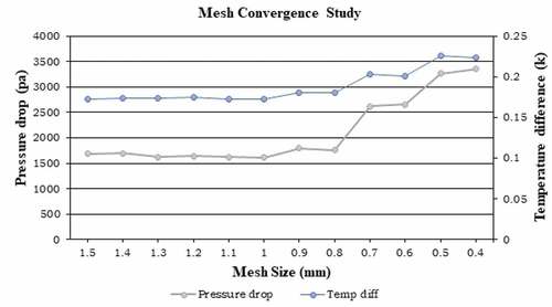
Figure 2. Plot of mesh convergence study (mesh Independence test).
3.1. Meshing
The mesh independence test with temperature and pressure as key parameter has been carried out to establish the convergence as shown in figure . The results reveal that values of both ΔP and ΔT converge respectively from mesh sizes of 0.5 mm. Therefore, a mesh element size of 0.5 mm and corresponding mesh generating rules were selected for the analysis.
3.2. Governing equations
3.2.1. Newton’s law of cooling
The primary governing equation reigning the present analysis is the Newton’s law of cooling. According to the Newton’s law of cooling, the amount of heat dissipated due to movement of fluid can be found by the equation given below:
where is the heat transferred out the body,
is the cooling plate temperature,
is the ambient temperature and
is the convective heat transfer coefficient (Huang et al., Citation2019).
4. Results
In the present study, five different plates with 3, 4, 5, 6 and 7 number of channels were numerically studied to evaluate the cooling performance under the identical boundary conditions. Cooling plates are named as S3, S4, S5, S6 and S7 indicating the respective number of channels. Analysis is carried out at a constant mass flow rate of 0.002 kg/s (Huo et al., Citation2015). Eventually cooling plate with least pressure drop (and hence least flow resistance) of the coolant is selected which is ideal for any heat exchanger (Gusew & Stuke, Citation2019). It is further analysed under different temperature conditions ranging from 300 K to 328 K to evaluate its cooling performance.
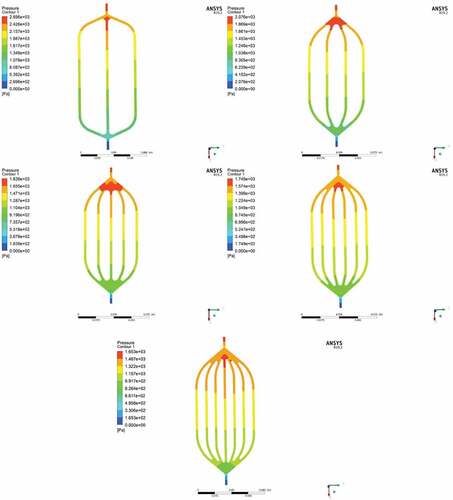
Figure 3. Pressure contours of cooling plates from S3 to S7.
4.1. Pressure analysis for different designs of cooling plate
figure shows the pressure contours of different streamline cooling plates-S3 to S7. The high-pressure zone is located at the inlet tunnel. It is evident from the figure that the pressure at the inlet tunnel decreases with increasing number of plates which implicates reduction in flow resistance. Implementation of streamline in cooling plate design also resulted in fairly uniform pressure distribution among each plate. The maximum pressure recorded is as follows: 2695.81 Pa, 2076.23 Pa, 1839.27 Pa, 1748.9 Pa and 1652.75 Pa for S3, S4, S5, S6 and S7 respectively.
4.2. Thermal analysis for different designs of cooling plate
figure represents the temperature contours of cooling plates (S3 to S7). It can be noted that for all models, the temperature is less near inlet and gradually increases along the flow length. It also shows the absorption of heat by coolant where maximum temperature is 298.304 K,298.327 K,298.135 K,298.24 K and 298.244 K for S3, S4, S5, S6 and S7 respectively.
Figure 4. Temperature contours of cooling plates from (S3 to S7).
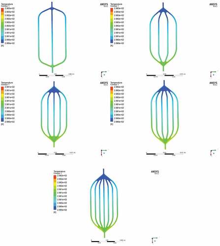
Figure 5. Velocity contour of cooling plates from (S3 to S7).
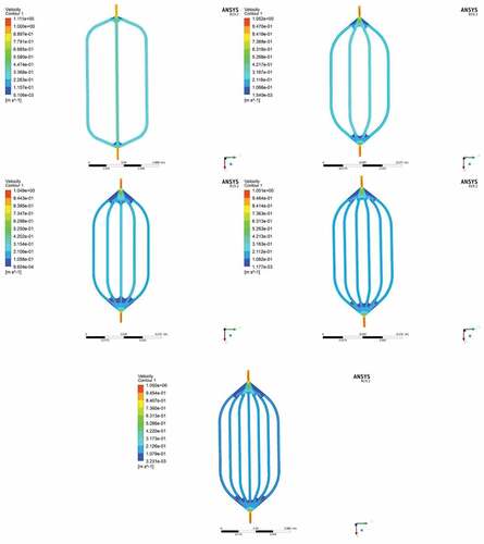
4.3. Velocity analysis for different designs of cooling plate
figure represents the velocity contour of different cooling plates S3 to S7 which are consistent with the literature implicating that streamline cooling plates provide less flow resistance, by eliminating any means of the vortex and turbulence flow (Huang et al., Citation2019). The maximum velocity observed for all the plates is about 1.1 m/s2. The overall results of computational analysis are provided in Table .
Table 1. Results of numerically analysed cooling plates from S3 to S7
From the results provided in Table , it can be concluded that the plate configuration-S7 provides best thermo-hydraulic performance in terms of least pressure drop, low pressure at inlet region and maximum cooling effect compared to other plates. Henceforth, it is selected as optimal configuration and is its performance is further analysed by varying the temperature from 300 K to 328 K (Aldosry et al., Citation2021).
Figure 6. Temperature contours of Solid plate (S7) at 328 K.
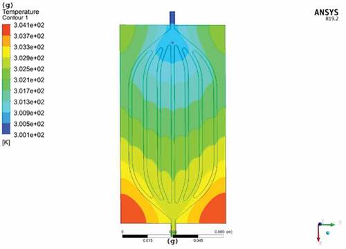
4.4. Thermal analysis of S7 cooling plate configuration
The thermal analysis of S7 configuration is performed with temperature ranging from 300 K to 328 K with similar boundary conditions (Aldosry et al., Citation2021). figure shows the temperature distribution along the plate at 328 K and the outcome of the analysis for S7 configuration at different temperatures is listed in Table .
Table 2. Results of Solid plate (S7) at different temperature conditions
Heat transfer rate depends upon the temperature difference (Leary, Citation2020). From figure , it can be seen that the region in vicinity of inlet is cooler compared to the region near the outlet. It can also be observed that the outer edges near inlet are at lower temperature compared to outer edges near outlet. This is because in beginning the temperature difference between the coolant and the plate is more in the inlet region, hence the coolant will absorb the heat from plate and maintains it at a lower temperature. But later on, the temperature difference between coolant and plate starts to reduce owing to the rise in coolant temperature due to increased heat absorption from the plate. Consequently, there is a gradual increase in plate temperature of plate along the flow path towards the outlet. The heat transfer rate reduces as the fluid is progresses through the channel, hence, the outer edges of plate at outlet is at higher temperature than outer edges at inlet. From Table , it is evident that S7 performs well at all different temperatures and exclusively at 328 K the maximum temperature is just about 304 K.
5. Discussion
Five plates of different configurations S3, S4, S5, S6 and S7 with 3, 4, 5, 6 and 7 number of channels respectively are numerically analysed with coolant mass flow rate of 0.002 kg/s. To validate the developed model in the present work, results are compared with (Huang et al., Citation2019) under identical boundary conditions and is found to be in well agreement with the same. It is clear from the figure that there is no layered velocity presence or any kind of local high velocity points in the horizontal channel to the inlet of two central channels which is normally present in straight channel plates (Huang et al., Citation2019). Since the flow velocity is considerably low in the aforementioned regions, there exists no vortex or flow obstructions. Similarly, the maximum velocity and maximum temperature values of the present work and the literature are around 1.1 m/s2 and 300 K respectively with mass flow rate of 0.002 kg/s. By comparing different values of simulation results, S7 is selected for further analysis. Thermal investigation shows that at temperatures ranging from 300 K to 328 K, the plate performs satisfactorily. From it can be seen that cooling performance is optimum for this configuration at 328 K while reaching a maximum temperature of 304.123 K. The maximum temperature is reduced by 7.8% for S7 configuration. The temperature values in the present work lies within 15°C to 35°C which is typically the optimal operating temperature range for lithium-ion battery.
5.1. Limitations of the current work
In the present work the optimal plate configuration-S7 is numerically analysed for temperature values upto 328 K. Henceforth, further analysis with temperature values above 328 K and different coolant mass flow rates are essential to ascertain that S7 configuration can be used in place of conventional cooling plates. The experimental analysis and validation of the simulation results are also essential to understand the applicability and practical hurdles with the use of cooling channel configurations adopted in present work.
6. Conclusion
In order to reduce the maximum temperature and local temperature difference of Li-ion battery used in EVs, streamline shaped cooling plates (liquid cooled) have been implemented in the present work. The performance of cooling plates of different configuration S3, S4, S5, S6 and S7 with 3, 4, 5, 6 and 7 number of plates respectively are computationally analysed. The analysis is intended to determine the optimal cooling plate configuration. Further, the performance of optimal plate configuration is evaluated at different temperatures ranging from 300 to 328 K. The results show that streamline cooling plates perform satisfactorily well at different temperature with S7 configuration performing the best at 328 K. The maximum temperature of solid plate is 302.677 K at a mass flow rate of 0.005 kg/s which is well within the optimal operating temperature range of Li-ion battery. Further experiments can be performed with various materials and different temperatures to study the effect of different parameters on the cells.
Acknowledgements
The authors thank the Department of Aeronautical and Automobile Engineering, Manipal Institute of Technology, Manipal Academy, Manipal for providing the computational facility to carry out this research.
Disclosure statement
No potential conflict of interest was reported by the author(s).
Additional information
Funding
Notes on contributors

Divya D Shetty
Divya Shetty working as Assistant Professor in the Department of Aeronautical and Automobile Engineering, Manipal Institute of Technology, Manipal Academy of Higher Education, Manipal, Karnataka, INDIA. She holds B.E. (Automobile Engineering), M.Tech (Thermal Engineering) and pursuing her Doctoral studies in (Battery Thermal management systems). She has a more than seven years of teaching and research experience. Her area of interest includes Internal Combustion Engines, Automotive Technology, and Battery Thermal management systems.
References
- Aldosry, A. M., Zulkifli, R., & Ghopa, W. A. W. (2021). Heat transfer enhancement of liquid cooled copper plate with oblique fins for electric vehicles battery thermal management. World Electric Vehicle Journal, 12(2), 55. https://doi.org/10.3390/wevj12020055
- Dasaradha Ramaiah, K., Surekha, P., Kotha, G., & Thangavelu, K. (2020). Mhd rotating flow of a Maxwell fluid with Arrhenius activation energy and non-Fourier heat flux model. Heat Transfer, 49(4), 2209–12. https://doi.org/10.1002/htj.21717
- Dixit, T., & Ghosh, I. (2015). . Renewable and Sustainable Energy Reviews, 41(C) (Elsevier), 1298–1311. https://doi.org/10.1016/j.rser.2014.09.024
- Gangadhar, K., Bhanu Lakshmi, K., Kannan, T., & Chamkha, A. J. (2020). Entropy generation in magnetized bioconvective nanofluid flow along a vertical cylinder with gyrotactic microorganisms. Journal of Nanofluids, 9(4), 302–312. https://doi.org/10.1166/jon.2020.1758
- Gangadhar, K., Edukondala Nayak, R., Venkata Subba Rao, M., & Kannan, T. (2021). Nodal/Saddle stagnation point slip flow of an aqueous convectional magnesium oxide–gold hybrid nanofluid with viscous dissipation. Arabian Journal for Science and Engineering, 46(3), 2701–2710. https://doi.org/10.1007/s13369-020-05195-x
- Gangadhar, K., Kannan, T., & Jayalakshmi, P. (2017). Magnetohydrodynamic micropolar nanofluid past a permeable stretching/shrinking sheet with Newtonian heating. Journal of the Brazilian Society of Mechanical Sciences and Engineering, 39(11), 4379–4391. https://doi.org/10.1007/s40430-017-0765-1
- Gangadhar, K., Kumari, M. A., & Chamkha, A. J. (2021). EMHD flow of radiative second-grade nanofluid over a Riga Plate due to convective heating: Revised Buongiorno’s nanofluid model. Arabian Journal for Science and Engineering, 0123456789. https://doi.org/10.1007/s13369-021-06092-7
- Gangadhar, K., Lakshmi, K. B., & Kannan, T. (2021). Thermal transport of magnetized Cu - Fe 3O 4 /water hybrid nanofluid over a curved surface. International Journal of Applied and Computational Mathematics, 7(5), 1–21. https://doi.org/10.1007/s40819-021-01125-z
- Gangadhar, K., Lakshmi, K. B., Kannan, T., & Chamkha, A. J. (2021). Stefan blowing on chemically reactive nano-fluid flow containing gyrotactic microorganisms with leading edge accretion (or) ablation and thermal radiation. Indian Journal of Physics. https://doi.org/10.1007/s12648-021-02179-x
- Gangadhar, K., Subba Rao, M. V., Ramana, K. V., Kumar, C. S., & Chamkha, A. J. (2021). Thermal slip flow of a three-dimensional Casson fluid embedded in a porous medium with internal heat generation. Journal of Nanofluids, 10(1), 58–66. https://doi.org/10.1166/JON.2021.1770
- Greco, A. (2015, November). Numerical and analytical modelling of battery thermal management using passive cooling systems (Lancaster University).
- Gusew, S., & Stuke, R. (2019). Pressure drop in plate heat exchangers for single-phase convection in turbulent flow regime: Experiment and theory. International Journal of Chemical Engineering, 2019(i), 1–11. https://doi.org/10.1155/2019/3693657
- Huang, Y., Mei, P., Lu, Y., Huang, R., Yu, X., Chen, Z., & Roskilly, A. P. (2019). A novel approach for Lithium-ion battery thermal management with streamline shape mini channel cooling plates. Applied Thermal Engineering, 157(November 2018), 113623. https://doi.org/10.1016/j.applthermaleng.2019.04.033
- Huo, Y., Rao, Z., Liu, X., & Zhao, J. (2015). Investigation of power battery thermal management by using mini-channel cold plate. Energy Conversion and Management, 89, 387–395. https://doi.org/10.1016/j.enconman.2014.10.015
- Jarrett, A., & Kim, I. Y. (2011). Design optimization of electric vehicle battery cooling plates for thermal performance. Journal of Power Sources, 196(23), 10359–10368. https://doi.org/10.1016/j.jpowsour.2011.06.090
- Jarrett, A., & Kim, I. Y. (2014). Influence of operating conditions on the optimum design of electric vehicle battery cooling plates. Journal of Power Sources, 245, 644–655. https://doi.org/10.1016/j.jpowsour.2013.06.114
- Kim, U. S., Yi, J., Shin, C. B., Han, T., & Park, S. (2011). Modelling the thermal behaviour of a lithium-ion battery during charge. Journal of Power Sources, 196(11), 5115–5121. https://doi.org/10.1016/j.jpowsour.2011.01.103
- Kotha, G., Munagala, V. S. R., Damerla, V. K., & Gorla, R. S. R. (2020). Newtonian heating effect on laminar flow of Casson fluids: Thermal analysis. Heat Transfer, 49(4), 2390–2405. https://doi.org/10.1002/htj.21727
- Leary, M. (2020). Detail DFAM. In Design for additive manufacturing. https://doi.org/10.1016/b978-0-12-816721-2.00004-x
- Liu, H., Wei, Z., He, W., & Zhao, J. (2017, August). Thermal issues about Li-ion batteries and recent progress in battery thermal management systems: A review. Energy Conversion and Management, 150, 304–330. https://doi.org/10.1016/j.enconman.2017.08.016
- Mahamud, R., & Park, C. (2011). Reciprocating air flow for Li-ion battery thermal management to improve temperature uniformity. Journal of Power Sources, 196(13), 5685–5696. https://doi.org/10.1016/j.jpowsour.2011.02.076
- Panchal, S., Khasow, R., Dincer, I., Agelin-Chaab, M., Fraser, R., & Fowler, M. (2017). Thermal design and simulation of mini-channel cold plate for water cooled large sized prismatic lithium-ion battery. Applied Thermal Engineering, 122, 80–90. https://doi.org/10.1016/j.applthermaleng.2017.05.010
- Park, S., & Jung, D. (2013). Battery cell arrangement and heat transfer fluid effects on the parasitic power consumption and the cell temperature distribution in a hybrid electric vehicle. Journal of Power Sources, 227, 191–198. https://doi.org/10.1016/j.jpowsour.2012.11.039
- Rao, Z. H., Wang, S. F., & Zhang, Y. L. (2012). Simulation of heat dissipation with phase change material for cylindrical power battery. Journal of the Energy Institute, 85(1), 38–43. https://doi.org/10.1179/1743967111Z.0000000008
- Ravdel, B., Abraham, K. M., Gitzendanner, R., DiCarlo, J., Lucht, B., & Campion, C. (2003). Thermal stability of lithium-ion battery electrolytes. Journal of Power Sources, 119–121, 805–810. https://doi.org/10.1016/S0378-7753(03)00257-X
- Ritchie, A., & Howard, W. (2006). Recent developments and likely advances in lithium-ion batteries. Journal of Power Sources, 162(2), 809–812. https://doi.org/10.1016/j.jpowsour.2005.07.014
- Rosa, P., Karayiannis, T. G., & Collins, M. W. (2009). Single-phase heat transfer in microchannels: The importance of scaling effects. Applied Thermal Engineering, 29(17–18), 3447–3468. https://doi.org/10.1016/j.applthermaleng.2009.05.015
- Salman, B. H., Mohammed, H. A., Munisamy, K. M., & Kherbeet, A. S. (2013). Characteristics of heat transfer and fluid flow in microtube and microchannel using conventional fluids and nanofluids: A review. Renewable and Sustainable Energy Reviews, 28, 848–880. https://doi.org/10.1016/j.rser.2013.08.012
- Sun, X., Li, Z., Wang, X., & Li, C. (2019). Technology development of electric vehicles: A review. Energies, 13(1), 90. https://doi.org/10.3390/en13010090
- Wang, Q., Jiang, B., Li, B., & Yan, Y. (2016). A critical review of thermal management models and solutions of lithium-ion batteries for the development of pure electric vehicles. Renewable and Sustainable Energy Reviews, 64, 106–128. https://doi.org/10.1016/j.rser.2016.05.033
- Ye, Y., Saw, L. H., Shi, Y., & Tay, A. A. O. (2015). Numerical analyses on optimizing a heat pipe thermal management system for lithium-ion batteries during fast charging. Applied Thermal Engineering, 86, 281–291. https://doi.org/10.1016/j.applthermaleng.2015.04.066
- Ye, Y., Shi, Y., & Tay, A. A. O. (2012). Electro-thermal cycle life model for lithium iron phosphate battery. Journal of Power Sources, 217, 509–518. https://doi.org/10.1016/j.jpowsour.2012.06.055
- Zhang, J., Li, X., He, F., He, J., Zhong, Z., & Zhang, G. (2017). Experimental investigation on thermal management of electric vehicle battery module with paraffin/expanded graphite composite phase change material. International Journal of Photoenergy, 2017, 1–8. https://doi.org/10.1155/2017/2929473