
 ?Mathematical formulae have been encoded as MathML and are displayed in this HTML version using MathJax in order to improve their display. Uncheck the box to turn MathJax off. This feature requires Javascript. Click on a formula to zoom.
Abstract
This paper puts forward a lead compensator- based PI controller for Demand Response (DR) loop which is included in the conventional Automatic Load Frequency Control (ALFC) model to improve the frequency control process of power system. Though DR is a good solution for ALFC but the vital problem in DR is the existence of communication delay between control centre and appliances. The proposed lead compensator can generate phase lead at the output of the DR loop to eliminate the adverse effects of the delay on the system performance. To verify the effectiveness of the proposed controller for ALFC problem, two different two- area transfer function models of power system are tested. At first the approach is analysed for a wind integrated two- area thermal power system, later the same is extended for a two- area hydrothermal system. The system dynamic performances in presence of proposed compensator are obtained with all the controllers tuned. The Particle Swarm Optimization (PSO) technique is used to tune all the controller parameters of the DR loop as well as the ALFC loop. The results demonstrate the usefulness of the proposed lead compensator in the event of communication delay and step load variation. Finally, the performance of lead compensator in DR exhibits robust performance even with the variation in disturbance parameters and operating conditions in the system
PUBLIC INTEREST STATEMENT
In a power system, load is always changing according consumer’s demand, and generation is to follow the load to maintain a steady system frequency and, therefore, system stability. ALFC mechanism maintains this power balance during load fluctuations. This balance can be maintained either by increasing the generation or by decreasing the load or a properly coordinated mix of the two options. DR is a method to maintain the power balance by decreasing the load by offering some incentive to the consumers, so that they will switch off some of their loads. Proper application of DR can reduce the possibility of system collapse caused by under frequency. But, DR has time lagging characteristics which affects system dynamic stability. This paper proposes a control methodology to reduce this time lag of DR so that system response can be further improved. Results show that the performance of the proposed controllers is very promising.
This paper proposes a lead compensator- based PI controller for delay compensation in DR to improve the performance and response of ALFC process. DR is a demand side energy management method and highly relevant to the modern- day power system operation and control.
1. Introduction
Automatic Load Frequency Control (ALFC) problem is one of the most vital issues of power system operation. Maintaining balance between generation and load together with system losses is essential for maintaining the frequency in a power system (Chakrabarti & Halder, Citation2010; Kundur, Citation1994). In conventional method of control, ALFC carries the sole responsibility of maintaining the balance.
Over the last few years, it is being observed that the electricity demand is changing more hastily and unpredictably, causing frequent and abrupt mismatch between supply and demand. It has posed a new challenge to the conventional ALFC.
Demand Response (DR) provides an additional opportunity for balancing the generation and demand from demand side by dropping or shifting consumers’ electricity usage. DR was first introduced by Shweppe et al. in 1980 to offer better reliability and security compare to traditional control system in terms of balancing generation and load (Schweppe et al., Citation1980). DR is the change in load/demand with respect to change in price from demand side. The collaboration of DR in ALFC increases the stability margin of the system and improves the system dynamic performance (Bhuyan et al., Citation2020, Citation2021; Pourmousavi & Nehrir, Citation2014). DR can act in conjunction with the conventional ALFC in a coordinated manner to enhance the frequency control mechanism of the system. DR participate in the frequency regulation process by sending switching signals to the controllable loads from demand side. Though DR is beneficial for frequency regulation but it cannot provide frequency control at required speed (Jay & Swarup, Citation2011; Samarakoon et al., Citation2012) because of communication delay in the DR process arising from demand side. This delay produces phase lag between input and output of the DR loop due to which switching on or off of the load cannot take place fast enough for frequency regulation. This leads to overshoot, instability and oscillation in system dynamic performances (Pourmousavi & Nehrir, Citation2014; Samarakoon et al., Citation2012). The presence of current harmonics in any induction heating system also deteriorates the system stability (Raman et al., Citation2021). Lead compensator is therefore required to be introduced in DR control loop to overcome these problems.
Renewable energy source like wind energy source is the most suitable energy generation to overcome the load fluctuation in modern power system in the next decades (Hassan, Citation2020; Hassan et al., Citation2020). Power system faces many instability issues due to uncertainties in integrated renewable energy sources. Wind integrated power system also faces some inertia issues due to introduction of power electronic devices in the grid connected wind generators (Chaine & Tripathy, Citation2019; Chaine et al., Citation2017; Mauricio et al., Citation2009). While the PI- controller of DFIG mainly provides fast recovery of the turbine speed during transient period, the PD controller is more sensitive for providing inertia support for frequency regulation (Chaine et al., Citation2015; Mauricio et al., Citation2009). Due to this PD controller of DFIG is of main interest when load frequency control is concern. Hence, compensation for the communication delay in the DR- loop and the design of PD controller of DFIG are required to be done simultaneously for regulating the frequency of the wind integrated power system.
Applications of delay compensators for different power system issues can be found in the literature. In Beiraghi & Ranjbar (Citation2016), an adaptive delay compensator (ADC) is used for robust wide area damping controller design of power system. Engagement of wide area measurement system (WAMS) is considered for mitigation of low- frequency inter- area oscillations caused by time delay (Abdulrahman et al., Citation2019). In Zhang et al. (Citation2012) and Mokhtari & Aminifar (Citation2014), conventional lead- lag compensator has been designed to compensate the phase lag produced at output of the control loop caused by remote signal delays, but none of these studies are related to DR loop in ALFC process. However, it is observed from the above works that the presence of communication delay in control loop adversely affects the system performance and even leads to the system instability.
A few works have been reported on the influence of communication delay in DR control loop for frequency regulation. These have considered a constant delay in the DR loop. In Pourmousavi & Nehrir (Citation2014), DR is introduced in LFC model for frequency regulation. In this study more emphasis has been given to the design of DR control loop in traditional LFC but no compensation for the delay in the DR loop is considered. This study is also limited to the application of DR in LFC for single area power system. In Babahajiani et al. (Citation2018) fuzzy based DR is incorporated in LFC for frequency regulation in a multiarea power system but delay issues in DR is not compensated separately by using any compensator. In Hosseini et al. (Citation2019) delay issues in DR control loop have been overcome by an ADC for a single area power system.
This paper has taken an attempt to design the DR control loop to compensate the delay issues for smooth frequency control in an inter connected power system. A new lead compensator is proposed in this work for mitigation of the delay problem in DR loop. The compensator consists of a washout filter, a lead compensator followed by a PI controller. All the parameters of the ALFC controller including the DR loop and also the PD controller of DFIG are tuned by using Particle Swarm Optimization (PSO). The PI controller parameters of DFIG are not optimized. These values have been taken from Chaine et al. (Citation2015). The performance of the proposed delay compensator in DR loop is examined by considering two different two area power system, a wind integrated two- area thermal system and a two- area hydrothermal power system. The optimal power share between DR and the supplimentary control are measured according to the PJM regional ISO/RTO real- time electricity market (Walawalkar et al., Citation2008).
The rest of the content of this paper is organized as follow: Section 2 explains the developments of the ALFC model. In Section 3, the proposed controller is analytically evaluated. Simulation results are presented in Section 4 and overall findings are discussed in Section 5. Lastly, the proposed work is concluded in Section 6.
2. Frequency response modelling
2.1. ALFC Modelling of two area power system
The concept of the study is analyzed by considering a two area first order linear transfer function model of power system. The parameters taken for the two- area system for simulation are mentioned in the Appendix. Each area of the power system is having a thermal and wind energy generation unit. A grid connected DFIG is considered for WECS. The main motto of this work is to get smooth frequency control. So, DR is familiarized in the traditional ALFC of the two- area power system. The delay in the system is considered as time varying delay whose value is taken in the range of 0–0.1 s for simulation. To compensate the communication delay present in the DR process, which jeopardize the system stability, a proposed two stage lead compensator- based PI- controller is designed in the DR control path of ALFC. The study is analyzed by simulating a two area inter connected power which shown in figure . The proposed delay compensated DR control loop is presented in figure .
Figure 1. Transfer function model of the test system with proposed DR controller.
Figure 2. Proposed controller for delay compensation in DR loop.
The DFIG based wind power sources are supplying real power to both the areas via the stator and rotor of the induction generator. Moreover, two end- to- end power electronics converters are connected with a DC link to build an interface between rotor and stator. This converter is capable to track wind energy over a wide range by using the principle of Maximum Power Point Tracking (MPPT; Chaine & Tripathy, Citation2019; Mauricio et al., Citation2009). The penetration of wind energy at the time of load perturbation makes the system lower inertia due to the existence of power electronics converter in DFIG. This power electronics converter affects the natural dynamics of frequency change with respect to real power change
in conventional generators. Ultimately, it averts from retorting change in system frequency. This inertia effect can be overcome through the grid side DFIG controller connected in wind energy conversion system (Mauricio et al., Citation2009).
In figure , capacity of each area is 2000 MW in which conventional generator is generating 80% of total and rest 20% frequency support from Wind energy conversion system. So, real power generation in each area-i (1,2) by conventional and non- conventional generator are and
respectively which are added in the system. DR- control loop provides additional adjustment of real power from demand side to each area of the system during the load perturbation. The DR power is added to both the area. The only real power is subtracted from the system is load deviation power
. As the system is interconnected power system, so tie line power deviation
is exist in the system and it will be adding to the particular area of the system if the area is being paid power from the tie line or else it will be subtracted.
When the load perturbation occurs in either area of the system the generation and demand side power changes immediately to match the new load in each area. At steady state the power balance equation for any area-i can be expressed as:
where, Hz/pu. MW,
second.
is power system gain,
is damping constant and
is power system time constant,
inertia constant of area-i and
is the nominal frequency of the system in Hz.
So, frequency aberration of area-i due to load perturbation can be derived from (1) as..
Note that in (3) all the real power deviations and frequency deviation are in s-domain and are in per unit value for the analysis.
2.2. Inertia control DFIG
This section elaborates about the inertia control method of grid connected DFIG. The DFIG based wind turbine connected in the system which is not capable to control the inertia effect automatically, as it is uncoupled from grid by the grid side converter. Therefore, additional controllers are used to make the DFIG capable to give further signal while providing the active power from the wind energy source for the frequency support. figure shows the inertia control DFIG.
Figure 3. Transfer function model of DFIG controller.
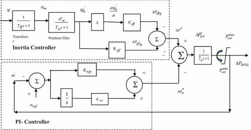
The inertia control DFIG provides an additional power signal to the nonconventional generator along with the reference power signal. This additional signal is expressed in 4; Chaine & Tripathy (Citation2019). The nonconventional DFIG based wind generator system measures the frequency deviation by the transducer and passes it through a high pass washout filter to the additionally used inertia controller.
where and
are the control parameter of the frequency deviation and the gain parameter of the derivative of frequency deviation respectively. The value of these parameters affects the inertia of the system.
The PI controller present in the DFIG system helps for fast speed recover subsequently the transient period is over. This controller is a low inertia controller whose parameters do not vary significantly for optimization (Chaine et al., Citation2015). Hence the proportional gain constraint and integral gain constraint
of PI- controller of DFIG are chosen from Chaine et al. (Citation2015). The reference power
computed by the PI controller which takes the input as the speed variation
as shown in figure is expressed in 5; Chaine et al. (Citation2017).
So, the total active power inserted to double fed induction generator can be uttered as follows Pal Verma & Kumar (Citation2012):
As the transient period ends within second, so the reference power signal from PI controller may be considered as constant and ,hence the net output power injected from DFIG to either area of the power system may be expressed as Pal Verma & Kumar (Citation2012):
To analyze the effect of inertia control on the frequency regulation, the derived power balance equitation in (3) is used for the analysis. By considering (4) and (7) in (3), we get the time domain power balance equation as below:
(Note: for area-i it is assumed that )
The s-domain representation of (9) is expressed in (10).
where,
The new inertia constant is obtained by arbitrarily varying the controller gain
. The system inertia increases with +ve value of
and this is possible within a feasible margin. Similarly, the damping constant
of the system is increased with +ve value of
. So larger value of
can provide better frequency damping.
Therefore, it proves that inertia control of DFIG is capable to increase the inertia of the system while supporting for frequency control of a wind integrated power system. So, the value of DFIG controller parameters and
are optimized in this work when DR is familiarized in conventional ALFC of the test model. The controller gains are tuned on the basis of getting smooth frequency regulation with lesser transient error and settling time with the help of PSO.
2.3. Mathematical background with DR
The introduction of DR in ALFC enhances the frequency regulation process by sharing additional load between the DR control loop and the secondary LFC loop itself. This can be mathematically expressed as follows:
where, are the power sharing from supplimentary and DR control in ith control area of the power system respectively.
The frequency deviation due to load perturbation in any area-i is analyzed through power balance equation in (10). The proposed DR control loop shares additional power which is shown in figure . The work included the modified DR control loop for smooth frequency control. The transfer function of the forward DR control path is mentioned in section 4.3.
The steady state frequency deviation for the test system has been derived in (10) to examine the role of DR in frequency control process in which load is assumed to be disturbed in either area. In figure , and
= delay time in ith control area.
Figure 4. Modified ith area wind integrated power system model with delay compensated DR model in frequency control loop.
From (10),
where,
As is step load change and it is a constant term in the system. So, the transfer function of the step load variation can be considered as:
After considering (18) in (17), the frequency deviation at steady state can be uttered based on final value theorem as below:
The tie line power is assumed to be zero at steady state.
where,
In (23) the expression is the frequency bias of the system i.e,
So, after including
in (20), the steady state frequency deviation can be expressed as:
It can be concluded from (24) that if load trouble size meets with the combined control power contributed from supplimentary control and DR- control loop, the frequency deviation can verge to zero at steady state. So only supplimentary control is not sufficient to force the system having zero frequency deviation at steady state. In addition, DR control gives more freedom to neutralize the frequency aberration at steady state as it complements the supplimentary control in LFC. So, introduction of DR in LFC could able to regulate the frequency in more reliable way. Also, it helps ISO/RTO for economic power system operation. In order to achieve good frequency regulation at steady state the control effort in LFC is splitted between the supplimentary and DR control loop.
3. The proposed approach
3.1. Stability analysis with proposed controller
The stability of the dynamic interconnected power system can be easily analyzed through small signal stability study. The present study investigated through system modelling and state- space representation. Here the two- area wind- integrated DR—LFC model is represented with its first order transfer function approach. The formulation of state- space equation for the proposed model highly depends of the general form of equation represented in 25; Kundur (Citation1994); Shankar et al. (Citation2016).
where ,K are state variable and control variable vectors respectively. The matrices A, B, C are the constant matrices and its dimension depends on the system problem. Referring to those above general form of state equation, the state variable vector for the proposed system is represented as tails:
Mainly the stability test for the present study is analyzed through the damping factor and eigen values calculation. The higher values of the damping ratio indicate more degree of stability of the system and vice versa.
Hence, proper selection of all controller gains are required for complete progress in performance of the system.
3.2. Synthesis of lead compensator
Though DR is a challenging process for frequency regulation of modern power system but, DR delay produced phase lag which causes the system unstable and oscillatory. The present issue may be solved by the use of lead compensator in the DR control path, as lead compensator is capable to decrease overshoot. Also, it speeds up the system performance. Therefore, lead compensator has been coupled with a PI based DR controller to improve the system overshoot.
The lead compensator circuit shown in figure is capable of producing phase lead output signal when phase lag input is applied to it. The transfer function of the compensator network can be expressed based on the general transfer function as..
Figure 5. Phase lead network.
Let ,
From (28),
where,
,
where () is frequency bias. To get frequency response we put,
.So, (30) is expressed in frequency domain as..
Phase response of the frequency response can be derived as below..
The basic condition for maximum compensation is
where, ,
This, is the design parameter to build a lead compensator. This can be obtained by tuning the parameter for the better performance of the system or can be obtained by analyzing the system stability in presence of lead compensator and any stability criterion like bode plot criterion, Nyquist stability may be used to get the compensator parameters. In this study
&
are chosen for better phase compensation of system and whose values are generally specified in (Abdulrahman et al., Citation2019).
3.3. The structure of two stage lead compensator plus PI-based DR delay controller
The structure of double lead plus PI based DR controller is implemented with conventional ALFC to reduce the influence of communication delay on DR loop for frequency control which is shown in figure . Though DR- controller can provide the cost- effective way of frequency control but the existence of delay in DR loop leads the system into phase lag. The controller structure consists of a participation factor, a washout filter, two- stage lead compensator and a PI controller. The participation factor provides the information to the DR about the quantity of sharing power to be adjust from demand side. The washout filter serves like a high pass filter with time constant , whose value for the study is taken as 6 seconds (Kundur, Citation1994). The lead compensator is used to reduce the overshoot created in the processing signal in DR loop due to the existence of delay in it. The output of the lead compensator block (ΔPc) passes through a PI controller block to get smooth frequency regulation for the overall system. The overall transfer function of the proposed DR controller is stated as
where, is transfer function of the projected controller model and
is DR participation factor.
is proportional gain parameter,
integral parameter of PI controller in DR loop.
3.4. Problem formulation
Frequency regulation is the vital aspect of the power system. The problem associated with the frequency control of power system are frequency deviation, occurrence of damping and delaying in settling time of the dynamic response of the system. In the present study, DR is participated in frequency control process. Though the participation of DR enhances the frequency control process but it badly effects the system damping and ultimately affect the stability because of presence of delay in DR loop. In addition to the DR controller, inertia control DFIG is used for frequency support from WECS. So that the damping effect in DR loop and inertia effect in wind energy sources are reflected in frequency deviation and overall settling time of the dynamic response. And hence, the objective of the present problem of the study to minimize either any one from frequency deviation and total settling time or minimize both. So, in this contest the generally used performance indices like Integral of Time Multiple of Absolute Error (ITAE), Integral Time Square Error (ITSE), Integral Absolute Error (IAE) and Integral Square Error (ISE) are tested for better performance of the system. Then, ITAE is considered as one of the objective functions for tuning controller gain, because it contributes more reduction in settling time and overshoot of the system. The second objective function is considered as overall settling time of the two- area power system. Hence the multi objective optimization problem is formulated as Rajasomashekar & Aravindhababu (Citation2012):
where, is total settling time which is the summation of settling time of frequency deviation in area-1, settling time of frequency deviation in area-2, and settling time of tie- line power deviation.
are obtained by optimizing
individually.
are obtained by optimizing
individually.
The optimization problem is considered as minimization problem subjected to
,
,
,
,
The PSO is used to tune the above five controller parameters to get minimum settling time and frequency deviation (ITAE). The optimization problem has been solved by PSO algorithm shown in figure . Then the stability test has been carried out by using eigen value analysis.
Figure 6. PSO flow chart to tune control parameters.
4. Simulations and results
The integration of non- conventional energy sources like Hydro, Solar, Wind etc. into the modern power system is gaining more and more reputation. Hence, Hydro and Wind are integrated into thermal system in a two- area power system in separate simulation model for the present study. Then, the proposed delay compensated DR loop in introduced in LFC of both the simulation model and frequency analysis for the two- area system is performed. The MATLAB and SIMULATION TOOLBOX is used to simulate the proposed models. At first the proposed controller is examined with a wind integrated two- area thermal power system which is shown in figure . Additionally, the same proposed controller is tested for a hydro- thermal two- area power system which is opted from Bhuyan et al. (Citation2021). The capacity of each area of both the test model are assumed as equal in capacity i.e 2000 MW. Wherever, in the first test model, the contribution of frequency support from DFIG based WECS is same in both the area i.e. 20% of total capacity of the area. The system performances are observed by considering 1% step load variation in area-1. To concise the paper, the system performances are analyzed only for 30% DR contribution in LFC. The controller gains for each test models are tuned by using PSO (Poli et al., Citation2007). All the results for each test models are narrated in the following sub- sections.
4.1. Approach for Wind integrated two area thermal power system
In this section, the system model is simulated for figure whose parameters are given in appendix. The capacity, the contribution of frequency
Support from DFIG and contribution of DR in LFC of each area of the systems are assumed identical for the study. Hence, the values of the controller parameters are optimized and supposed to be equal in both the areas.
4.1.1. Comparison of proposed delay controlled DR in ALFC with other controllers in ALFC
The proposed method has considered the limitation and technical issues in Chaine & Tripathy (Citation2019); Chaine et al. (Citation2017) and enhances the system performance by implementing the modified DR controller in LFC of the system. Then the proposed controller is tuned with PSO along with the existing controller in Chaine et al. (Citation2017), in coordinated manner considering objective function in (35). Then with the help of those tuned controller parameters, system dynamic performances are analyzed and are compared with existing controller in Chaine & Tripathy (Citation2019); Chaine et al. (Citation2017) which are shown in figure . The dynamic time domain responses of frequency deviations in two areas i.e, and tie line power deviation
are obtained for 1% step load change in area-1.
Figure 7. The tie line power deviation and area frequency deviations for 1% load change in area-1 for different schemes of controllers.
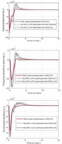
Further, with the proposed optimized controller parameters, several performance indices which has not been optimized in the objective function are also evaluated and compared the performance with other existing controller for LFC problem. Corresponding parameters are tabulated in Table . Table shows lower values of settling time, ITAE and higher value of minimum damping ratio (MDR) with proposed controller in LFC of the test system. Results confirm the better performance with proposed controller.
Table 1. Comparison of performance indices and MDR with different controllers in LFC by considering 20% frequency support from DFIG
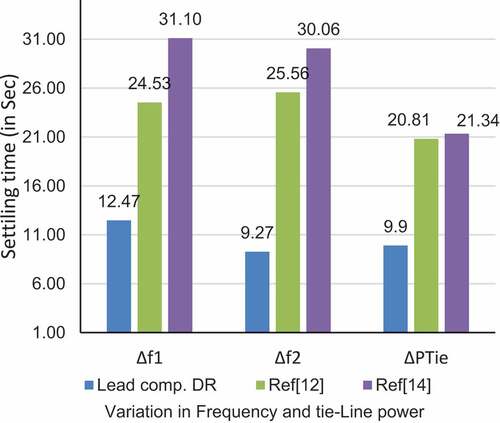
For proper visualization of enhancement in system execution in terms of speed and stability with proposed delay control DR in LFC as compare to other existing controller in LFC (Chaine & Tripathy, Citation2019; Chaine et al., Citation2017), different performance indices like MDR and settling time are compared through bar diagram representation shown in figure , figure respectively. The result shows improved performance with proposed controller as compared to the existing controller for LFC problem in literature (Chaine & Tripathy, Citation2019; Chaine et al., Citation2017).
Figure 8. Comparison of MDR with different controllers.
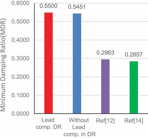
Figure 9. Verdict of settling time with different controllers.
4.1.2. Comparison between lead compensator in DR and without lead compensator in DR controller
In the proposed study, lead compensator has taken major role to mitigate time delay effect in the DR control loop. So, the DR controller parameters and the inertia control parameters of DFIG are tuned in synchronized way for different objective functions. The best compromise results are obtained when the objective function is formulated as weighted sum normalized form of multi objective optimization considering as single objective problem as mentioned in (35). Corresponding results are presented in Table . Further, the stability of the power system is verified in occurrence of the proposed controller by eigen value calculation. Table shows the comparison results of several performance indices and eigenvalues obtained with tuned controller parameters in presence of lead compensator in DR- LFC and in absence of lead compensator in DR- LFC. The result shows that lead compensator can improve the overshoot of the system and proposed controller does not affect the stability of the system, moreover it can able to improve the oscillation of the system as MDR is improving.
Table 2. Best compromised output with lead compensator DR in ALFC for 1% load variation in area-1
Table 3. Comparison of several performance indices and maximum overshoot with tuned controller gain
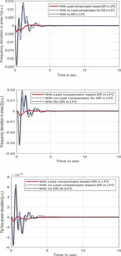
The time domain performance of tie- line power deviation and frequency deviation in both the areas i.e,
are obtained for the best compromise solution with and without lead compensation in DR loop. shows corresponding time domain responses of the test system. For proper visualization of improvement in overshoot with lead compensator has been represented by bar diagram shown in .
Figure 10. The tie line power deviation and area frequency deviations for 1% load variation in area-1with lead compensator in DR and without lead compensator in DR.
Figure 11. judgment of maximum overshoot with and without lead compensator in DR controller.
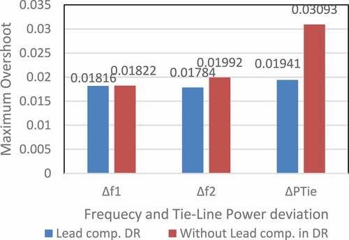
The multi objective optimization is carried out by considering the objective function in (35) with and without lead compensator in DR loop and the results are shown in Table . The result in Table shows lower values of settling time, ITAE, maximum overshoot and higher values of MDR when lead compensator introduced in DR loop. These results verify the effectiveness of lead compensator for improvement in system performance indices like maximum overshoot, settling time, ITAE and MDR.
4.2. Approach for wind integrated two area hydrothermal power system
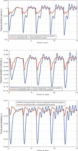
The contest with the Hydrothermal system is the difference between their governor characteristics of individual hydro and thermal unit (Nanda et al., Citation2006). Due to high water inertia in hydro system, it arrests the frequency deviation earlier than thermal system. Hence overall system performance may vary from merely thermal two area power system. In this section of approach, the hydrothermal system is tested (Bhuyan et al., Citation2021). In the model each area of the power system is having capacity of 2000 MW. The area-1 is having a thermal system of same nominal parameter as thermal system in . The area −2 is having a hydro unit whose nominal parameters are taken from Bhuyan et al. (Citation2021). The LFC integral controller parameters (Ki1 = integral gain of thermal unit, Ki2 = integral gain of thermal unit) and proposed DR controller are optimized in coordinated manner with PSO by considering the objective function in (35) to get better dynamic performances of the system. The system behavior is analyzed and controller gain are tuned by assuming 1% load variation in thermal (area-1) unit. Several performance indices of the system like ITAE, IAE.ITSE, ISE and MDR are obtained with the tuned controller which are shown in Table . To verify the effectiveness of the proposed DR controller in LFC of Hydrothermal system, the time domain performances like frequency deviation in both the area and tie line power deviation
are obtained for 1% step load change in area-1. Moreover, the same performances are compared with the performances of the hydrothermal system when DR present in the system without any delay compensation and in absence of DR in LFC which are shown in . shows better dynamic performances with lead compensator- based DR controller in LFC. Also, it can be cleared from the , the lead compensator in DR loop improves the stability and reduces the peak over shoot in system dynamic performances. The reduction in values of time errors and increase in MDR value obtained in Table indicates effective contribution of lead compensated DR controller in LFC towards more degree of stability compared to other form of LFC techniques mentioned. Additionally, elucidates, only including DR in LFC of Hydrothermal system can able to reduce the settling time error but the lead compensator- based DR controller in LFC can capable to reduce the damping and peak overshoot.
Table 4. Comparison of performance indices and MDR with and without different DR controllers in LFC of a Hydrothermal inter connected power system
Figure 12. The tie line power deviation and area frequency deviations for 1% load change in area-1 with and without different DR controller for Hydrothermal system.
4.3. Sensitivity analysis with the proposed controller
To study the robustness of the proposed controller for the approached systems, the system parameters and operating conditions are varied. At first, the system parameters like washout filter time constant in DR loop (TW), WECS time constant (TA), Equivalent WECS inertia (He) for wind integrated thermal system in the range of +50% to −50%. in step of 25%. This sensitivity test has been done with PSO tuned controller parameter for proposed DR controller in LFC of wind integrated thermal system when 1% load change in area-1. Furthermore, the system performance indices such as ITAE, MDR and settling time for ,
are obtained with corresponding system parameter variations which are shown in Table . The results in Table proves that the variation in system parameters have not degraded the system performances and are merely changed for ±50% of parameters change.
Table 5. Comparison of several performance indices and maximum overshoot with tuned controller gain
Further to compare the robustness between the Hydrothermal system and Wind integrated thermal system in presence of proposed controller, a continuous operating load change has been assumed in the range of 0% to 50% in a step of 10% in area-1 for total simulation time. The sensitivity test has been done when PSO tuned controller parameters are used in the systems. The dynamic responses like and ΔPTie are obtained for both the test systems with continuous load change which are shown in . reveals that even for continuous load change, the system is hardly degraded their performances. Additionally, result shows Hydrothermal system is more robust with proposed controller for the continuous variation of operating load as compared to the wind integrated thermal system due to its higher inertia.
Figure 13. and
for continuous load change (from 0% to 50%) in area-1 without different DR controller for Hydrothermal system.
5. Discussion
In this section, the main outcomes, comparisons with other past studies and research carried out, implications and other critical analysis of the outcomes, strengths and weaknesses of the present studies are described as follows..
The improvement of this DR control scheme for frequency regulation over other published research work is the modified delay compensator in DR loop, which comparatively enhances the performance of the power system.
The results presented in the section 4 demonstrate that the proposed delay compensated DR controller is efficient for effective frequency regulation in a delay- introduced demand side frequency regulation scheme. This proposed delay compensator is working flawlessly for both wind integrated thermal system and hydrothermal system. Especially, due to the addition of modified lead compensator- based PI controller in DR loop collaborated with AGC, the overshoot, settling time, frequency deviation and tie- line power deviation are decreasing. Also, the system oscillations die out drastically faster thereby improving the system stability.
Though DR is a good solution for frequency regulation itself, but with the addition of modified delay compensator in DR, dynamic performances further improve the double of the earlier improvement of the power system in terms of overshoot, settling time, frequency deviations and tie- line power deviation. The simulation results for the wind integrated two area thermal test system reveals that, DR reduces the settling time of 23% while lead compensator- based DR could able to reduce the settling time of 56%. Similarly, while DR reduces the ITAE of 75%, the proposed controller in DR could be able to reduce it of 81%. Simulation results for two area hydrothermal test system reveal that, while DR reduces the settling time of 12%, lead compensator- based DR could able to more reduce the settling time of 44%. Similarly, while DR reduces the ITAE of 38%, the proposed controller in DR could be able to reduce it of 83%. Furthermore, it has been observed that damping ratio increases in the dynamic performances of both the test system with proposed delay compensated DR in ALFC. The damping ratios are mentioned in Table and Table for wind integrated two area power system and two area hydrothermal system respectively. This proves that stability increases with addition of proposed delay compensator in DR. Also, the robustness of the proposed controller is scrutinized for both the test system for various parameters variation in the range of ±50% and continuous load variation in the range of 0–50% of its nominal values. The results show that system performances are changing negligibly with the above load and parameter variations. Also, it has been observed that the proposed controller shows more robustness for hydrothermal system as compared to wind integrated thermal system.
The present study is limited to the application of the proposed modified delay compensator based DR controller to the two- area hydrothermal power system and two- area wind integrated thermal system. In future, it can be examined for widely spread integrated modern power system having conventional and many non- conventional power generations along with storage devices to check the effectiveness of the proposed controller. The uncertainty of wind is not envisaged in this model, whereas only 20% frequency support is considered from wind. Hence, in future the uncertainty issue can be considered for any renewable energy integrated in the system for frequency regulation in presence of proposed delay compensated DR controller. The participation factor for DR contribution in ALFC is considered fixed in this study; it may be optimized in future.
6. Conclusion
To summarize, this extensive study analyzes the frequency regulation in ALFC of a DR collaborated power system. The significant shortcoming in DR is communication delay that appears in the system during sending commands from the control center to controllable loads for balancing the system and receiving response. Therefore, in the present study, a modified delay compensator is envisaged to enhance the effectiveness of DR for frequency regulation. The modified delay compensator is a lead compensator- based PI controller in DR loop. The performance of the proposed controller is examined by considering two different two area power system i.e, hydrothermal and wind integrated thermal system as test systems. For the wind integrated thermal system, DFIG based wind is considered for frequency support. In addition, the inertia effect on thermal system due to the integration of DFIG is taken care in the study by considering a PD- inertia controller in it. The performance analysis is done by simulating the transfer function model of the test systems in MATLAB Toolbox. The simulation results are examined with tuned values of all controller along with the modified DR controller for frequency regulation. A normalized form of weighted sum PSO multi objective optimization is used to tune the controller parameters designed in the above test systems for smooth frequency regulation. The stability and robustness of these systems with the proposed controller are analyzed through eigen value calculation. The result exhibits better efficiency with proposed controller. Furthermore, the dynamic performances of the test systems show better results than earlier works in literature. Finally, the sensitivity analysis of the proposed controller for two area wind integrated thermal system and Hydrothermal system shows negligible difference in system performances even with parameter variation in the range of ±50% and continuous load variation in the range of 0% to 50% of its nominal values. However, the study to check the performance of proposed delay compensator is limited to some selected power system. Future work will further investigate the performance of proposed controller for different power system integrated with renewable energy sources and storage devices.
Disclosure statement
No potential conflict of interest was reported by the author(s).
Additional information
Funding
Notes on contributors

Swetalina Bhuyan
Swetalina Bhuyan is an Assistant Professor in the Department of Electrical Engineering, Modern Engineering and Management study, Odisha, India. Currently she is a Ph.D. research scholar in the Department of Electrical Engineering, Jadavpur University, Kolkata, India. Her research interests include power system operation and control, distributed generation, energy management in special demand side management.
Sunita Halder Nee Dey
Sunita Halder Nee Dey and Subrata Paul are currently Professors in the Department of Electrical Engineering, Jadavpur University, Kolkata, India. Research interests of Prof. Halder include power system operation and control, voltage stability, FACTS applications, sustainable energy, microgrid, distributed generation, energy management, whereas, area of interests of Prof. Paul include power system operation, power system dynamics and control, power system optimization, and distributed generation.
References
- Abdulrahman, I., Ismael, R., & Belkacemi, G. (2019). Power oscillations damping using wide- area- based solar plant considering adaptive time- delay compensation. Springer.
- Babahajiani, P., Shafiee, Q., & Bevrani, H. (2018, June). Intelligent demand response contribution in frequency control of multi-area power systems. IEEE Trans on Smart Grid, 9(2), 1282–28. https://doi.org/10.1109/TSG.2016.2582804
- Beiraghi, M., & Ranjbar, A. M. (2016). Adaptive delay compensator for the robust wide-area damping controller design. IEEE Transactions on Power Systems, 31(6), 4966–4976. https://doi.org/10.1109/TPWRS.2016.2520397
- Bhuyan, S., Dey, S. H. N., & Paul, S. (2020). Role of demand side management in automatic load frequency control, International Conference on Emerging Frontiers in Electrical and Electronic Technologies (ICEFEET), NIT, Patna, India, (pp. 1–6). IEEE.
- Bhuyan, S., Dey, S. H. N., Paul, S., & Chaine, S. (2021). Analysis of frequency regulation for a hydro-thermal system with ALFC-DR model, In 2021 1st International Conference on Power Electronics and Energy (ICPEE), KIIT, Bhubaneswar, India, (pp. 1–5). IEEE.
- Chaine, S., & Tripathy, M. (2019). Performance of CSA optimized controllers of DFIGs and AGC to improve frequency regulation of a wind integrated hydrothermal power system. Alexandria Engineering Journal, 58(2), 579–590. https://doi.org/10.1016/j.aej.2019.03.007
- Chaine, S., Tripathy, M., & Jain, D. (2017). Nondominated Cuckoo search algorithm optimized controllers to improve the frequency regulation characteristics of wind thermal power system. Engineering Science and Technology, an International Journal, 20(3), 1092–1105. https://doi.org/10.1016/j.jestch.2017.05.005
- Chaine, S., Tripathy, M., & Satpathy, S. (2015). NSGA- II based optimal control scheme of wind thermal power system for improvement of frequency regulation characteristics. Ain Shams Engineering Journal, 6(3), 851–863. https://doi.org/10.1016/j.asej.2015.01.011
- Chakrabarti, A., & Halder, S. (2010). Power system analysis: Operation and control (3rd Edition ed.). PHI Learning Pvt. Ltd.
- Hassan, F. A. (2020). Multi- criteria approach and wind farm site selection analysis for improving power efficiency. Journal of Human, Earth, and Future, 1(2), 60–70. https://doi.org/10.28991/HEF-2020-01-02-02
- Hassan, F. A., Mahmoud, M., & Almohammed, O. A. M. (2020). Analysis of the generated output energy by different types of wind turbines. Journal of Human, Earth, and Future, 1(4), 181–187. https://doi.org/10.28991/HEF-2020-01-04-03
- Hosseini, S. A., Toulabi, M., Dobakhshari, A. S., Ranjbar, A. M., & Ranjbar, A. M. (2019, November). Delay compensation of demand response and adaptive disturbance rejection applied to power system frequency control. IEEE Transactions on Power Systems, 35(3), 2037–2046. https://doi.org/10.1109/TPWRS.2019.2957125
- Jay, D., & Swarup, K. S. (2011). Frequency restoration using dynamic demand control under smart grid environment. In Proc. IEEE PES Innovative Smart Grid Technologies—India (ISGT India), Kerala, (pp. 311–315). IEEE.
- Kundur, P. (1994). Power system Stability and Control. McGraw- Hill.
- Mauricio, J. M., Marano, A., Gómez- Expósito, A., & Ramos, J. L. M. (2009). Frequency regulation contribution through variable-speed wind energy conversion systems. IEEE Transactions on Power Systems, 24(1), 173–180. https://doi.org/10.1109/TPWRS.2008.2009398
- Mokhtari, M., & Aminifar, F. (2014, November). Toward wide-area oscillation control through doubly-fed induction generator wind farms. IEEE Transactions on Power Systems, 29(6), 2985–2992. https://doi.org/10.1109/TPWRS.2014.2309012
- Nanda, J., Mangla, A., & Suri, S. (2006). Some new findings on automatic generation control of an interconnected hydrothermal system with conventional controllers. IEEE Transactions on Energy Conversion, 21(1), 87–194. https://doi.org/10.1109/TEC.2005.853757
- Pal Verma, Y., & Kumar, A. (2012). Participation of doubly fed induction generator-based wind turbine in frequency regulation with frequency-linked pricing. Electric Power Components and Systems, 40(14), 1586–1604. https://doi.org/10.1080/15325008.2012.707289
- Poli, R., Kennedy, J., & Blackwell, T. (2007). Particle swarm optimization: An overview. Swarm Intelligence, 1(1), 33–57. https://doi.org/10.1007/s11721-007-0002-0
- Pourmousavi, S. A., & Nehrir, M. H. (2014, July). Introducing dynamic demand response in the LFC model. IEEE Transactions on Power Systems, 29(4), 1562–1572. https://doi.org/10.1109/TPWRS.2013.2296696
- Rajasomashekar, S., & Aravindhababu, P. (2012). Biogeography based optimization technique for best compromise solution of economic emission dispatch. Swarm and Evolutionary Computation, 71, 47–57.https://doi.org/10.1016/j.swevo.2012.06.001
- Raman, R., Dutta, S. K., Sarmah, P., Das, M., Saikia, A., & Sadhu, P. K. (2021, September). Feasible evaluation of shunt active filter for harmonics mitigation in induction heating system. HighTech and Innovation Journal, 2(3), 235–245. https://doi.org/10.28991/HIJ-2021-02-03-08
- Samarakoon, K., Ekanayake, J., & Jenkins, N. (2012, December). Investigation of domestic load control to provide primary frequency response using smart meters. IEEE Transactions on Smart Grid, 3(1), 282–292. https://doi.org/10.1109/TSG.2011.2173219
- Schweppe, F. C., Tabors, R. D., Kirtley, J., Outhred, H., Pickel, F., & Cox, A. (1980, May). Homeostatic utility control. IEEE Transactions on Power Apparatus and Systems, PAS-99(3), 1151–1163. https://doi.org/10.1109/TPAS.1980.319745
- Shankar, R., Chatterjee, K., & Bhushan, R. (2016). Impact of energy storage system on load frequency control for diverse sources of interconnected power system in deregulated power environment. International Journal of Electrical Power & Energy Systems, 79(July), 11–26. https://doi.org/10.1016/j.ijepes.2015.12.029
- Walawalkar, R., Blumsack, S., Apt, J., & Fernands, S. (2008, July). Analyzing PJM’s economic demand response program. In 2008 IEEE power and energy society general meeting- conversion and delivery of electrical energy in the 21st century, Pittsburgh, PA, USA, (pp. 1–9). IEEE.
- Zhang, P., Yang, D. Y., Chan, K. W., & Cai, G. W. (2012). Adaptive wide area damping control scheme with stochastic subspace identification and signal time delay compensation. IET Generation, Transmission & Distribution, 6(9), 844–852. https://doi.org/10.1049/iet-gtd.2011.0680
Appendix A
A.1 Nominal value of parameters for two area power system
In Figure “q” is number of areas and ,Synchronous coefficients, T12=0.0867sec. The capacity and contribution of DFIG in both the area are equal. So nominal value of the parameters of both the area of test system are identical. These parameter values are KP=120(Hz/pu.MW), Kr=0.5, Tr=10(sec), Tp=20(sec), f=60(Hz), Tg=0.08(sec), Tt =0.3(sec), R=3 (Hz/pu.MW), H=4.7104, D=8.33×10⁻³ (pu.MW/Hz), B=0.3417 (pu.MW/Hz)
A.2. Nominal parameters for DFIG
The parameters used in DFIG based WECS are TA=time constant of non- conventional generator, TR=transducer time constant, Tw=washout time constant, He=inertia constant of WECS, is maximum output of non- conventional generator,
is minimum output of non- conventional generator, Kwp, Kwi are proportional and integral constant of speed regulator respectively. These variables are presented in Table .
A.3 PSO variables
Number of populations=50, C1=2, C2=2, maximum inertia weight=0.9, minimum inertia weight=0.4, number of variables=5, maximum iteration=100
Table A. Nominal Parameters of DFIG BASED WECS (Chaine et al., Citation2017)