
 ?Mathematical formulae have been encoded as MathML and are displayed in this HTML version using MathJax in order to improve their display. Uncheck the box to turn MathJax off. This feature requires Javascript. Click on a formula to zoom.
Abstract
In this paper, a new adaptive tuned vibration absorber (ATVA) design is presented for suppressing the resonance of primary system. A cone-based continuously variable transmission (cone CVT) is proposed to integrate a dynamic vibration absorber (DVA) for retuning itself in response to a time-varying excitation frequency. The natural frequency of ATVA can be dynamically tuned over a wide range by varying the gear ratio of the cone CVT, resulting in a change in the system’s net mass moment of inertia. To predict the system response for various design parameters, a mathematical model is developed. The simulation of this model is employed through MATLAB software. The analytical model is numerically evaluated by tuning the frequency from 3.27 to 7.43 Hz. The results indicate that the proposed scheme may greatly increase the frequency bandwidth of the absorber while also suppressing the primary system’s resonance. This indicates that the work is applicable to ATVA’s practical applications.
PUBLIC INTEREST STATEMENT
Adaptive technology is crucial in the case of tuned vibration absorbers, since the small damping need of the spring element in a mistuned condition might cause the structure to vibrate at harmful levels. In this instance, mistuning can be produced by either a drift excitation frequency or a drift in the natural frequency owing to environmental conditions. Therefore, a tuned vibration absorber must be adaptable for practical application.
1. Introduction
Generally, machines and dynamic system are exposed to a constant alternating force with a constant frequency. If the frequency of excitation is equal to or close to the structure’s resonance frequency, this forcing may cause excessive vibrations. These vibrations may result in the destruction or sudden failure of machines or structures. As a result, the use of dynamic vibration absorbers (DVA) is proposed to mitigate the systems’ extreme vibrations.
The dynamic vibration absorber application is invented by Frahm (Frahm, Citation1909). Because of its simple construction and apparent effect in vibration control applications, it has been widely employed in suppressing unwanted vibrations (Chung, Citation2004; Mori et al., Citation2010; Viet & Park, Citation2011; Webster & Vaicaitis, Citation1992; Wu, Citation2008). The DVA, on the other hand, is a single-frequency vibration control device that operates exclusively within a narrow range of exciting frequencies. When the exciting frequency is variable, the DVA’s vibration attenuation effect commonly decreases as a result of mistuning (Inman, Citation1994). As a result, in order to handle various excitation frequencies, the DVA must have an adjustable natural frequency. To achieve this propose, an adaptive tuned vibration absorber (ATVA) has been invented (Brennan, Citation1999; Sun et al., Citation1995; Von Flotow, Citation1994). Because it does not require high-level power signals for an active system, the ATVA consumes less energy than an active vibration absorber. Additionally, the ATVA is a fail-safe system since it can operate as a passive vibration absorber in the event of a power outage.
Many studies have developed new configurations for ATVA in order to increase the operating frequency range and improve the vibration reduction performance. Nguyen et al. (Citation2020) conceived and designed an adaptive neural network controller for a MRE-based absorber to be installed on the suspension. Dong et al. (Citation2020) developed an MR torsional vibration absorber with variable stiffness to control powertrain vibration. Kumbhar et al. (Citation2018) developed an adaptive tuned vibration absorber using magnetorheological elastomer-shape memory alloy composite. Yuan et al. (Citation2019) suppressed mode coupling chatter for robotic machining by using a semi-active magnetorheological elastomer absorber.) Hu and Chen (Citation2015) showed that adding an inerter to a damper without a spring has little effect on performance, whereas attaching the inerter to a vibration absorber with both a damper and a spring significantly improves performance. Jin et al. (Citation2019) proposed two inerter-based configurations for beam-type structural vibration suppression. Under harmonic loads, they demonstrated that the inerter base vibration absorbers are more efficient than conventional DVAs, particularly when the mass ratio is modest. Almashhor and Asiri (Citation2021) proposes a control approach based on variable mass tuned vibration absorber to suppress the primary system’s resonance. Homaeinezhad et al. (Citation2020) developed novel intelligent actuators capable of absorbing the MIMO vibrational systems. Brzeski et al. (Citation2015) proposed using a device with an inerter, which allows for precise changes in inertance. They demonstrated that a continuously variable transmission (CVT) with a gear-ratio control system can accomplish such a characteristic. In their later publication (Brzeski et al., Citation2017), they reported the experimental model of this innovative vibration absorber. To characterize the system, they conducted various experiments. They also used numerical simulation to show that the inerter base vibration absorber prototype with the CVT has significant dampening properties across a wide range of vibration frequencies. Sadeghian et al. (Citation2022) suggest an inerter-based device for structural vibration control in which the inertance may be changed based on the excitation frequency. The suggested device is able to generate a variable inductance and frequency via the CVT’s core in a smooth and seamless manner.
This paper proposes new adaptive tuned vibration absorber for neutralization of vertical vibration of primary system. The key design goals are to create a system that can tune itself to a wide range of excitation frequencies and accomplish this tuning operation with low energy consumption. To achieve these goals, the design described in this study installs a cone CVT between absorber mass and primary mass for enabling effective vibration control over a range of frequencies. The natural frequency of the proposed ATVA can be dynamically tuned over a wide range by adjusting the position of the transmission wheel. The suggested concept has the advantages of a passive vibration absorber with low power consumption and the flexibility of an active device. This paper is organized as follows: In Section 2, working principles of the proposed cone CVT are presented. In Section 3, mathematical model and bandwidth of the proposed ATVA are derived. In Section 4, lookup table is proposed to tune the position of the wheel. In Section 5, the results of numerical study are presented, while the last section summarizes the obtained results.
2. Working principle of the proposed cone CVT
shows the isometric view and schematic model of the proposed cone CVT. The cone CVT consists of two cones which are covered with friction material and a wheel which is connected to a slider. The wheel is situated between the input and output cones. The moment is transmitted from input cone to output cone via a wheel. The gear ratio are altered by changing the ratio of the radii between the input and output cones by adjusting the position of the wheel. In this model, the slider is driven by a stepping motor through a ball screw to tune the position of the wheel.
Figure 1. (a) Isometric view of cone CVT. (b) Schematic model of cone CVT.
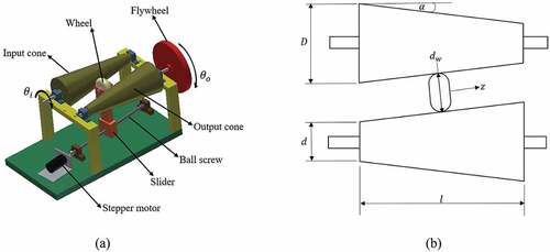
It is assumed that no slip occurs between cones and the wheel; therefore, the gear ratio between the input cone and the output cone can be expressed as:
Where
The gear ratio
The bigger diameter of the cone
The smaller diameter of the cone
The length of the cone
Taper angle
The diameter of the wheel
The wheel position
The angular displacement of input cone
The angular displacement of output cone
It is noticed that the gear ratio of cone CVT depend on the wheel position.
The torque exerted on the shaft of input cone can be written as
Where
The torque exerted on input cone
The moment of inertia of input cone
The moment of inertia of output cone
The moment of inertia of flywheel
3. Mathematical modelling of a presented ATVA
presents the schematic of primary structure which is coupled with a proposed ATVA. The primary structure is modeled by two springs that are connected in parallel and a mass and excited by harmonic force. The ATVA consists of a vibrating mass and a spring. A CVT gearbox is also mounted between absorber mass and primary mass. The absorber mass is connected to the CVT gearbox by using rack and pinion mechanisms.
Figure 2. Proposed ATVA attached to 1 dof primary system.
The application of Newton’s second law of motion to each of the masses gives the equations of motion:
where is the displacement of the primary structure,
is the displacement of the absorber mass,
is the absorber mass,
is the primary structure mass,
is the stiffness of ATVA,
is the stiffness of the primary structure,
is the pitch diameter of the pinion that cooperates with the moving rack, and
.
Holding the primary system fixed, the equation of motion of the absorber mass alone will be as follows:
Therefore, the natural frequency ω of the presented DVA is
Where
Equation (6) indicates that the natural frequency can be tuned by adjusting the position of the wheel.
By assuming harmonic solution,
and
The steady-state amplitude of primary structure can be expressed as
By defining
From the definitions above, the magnitude displacement dynamic amplification factor of the primary structure can be derived by
This system’s bandwidth (BW) can be defined as the range of frequencies at which the magnitude displacement dynamic amplification factor is below a specific threshold, . To determine the bandwidth, the Eq. (8) should be equated to the provided value of
and solve for the two
values that will yield the lower and upper bounds of the operating range as follows:
The normalized bandwidth of this system can be determined as
4. Tuning of the wheel position by lookup table
Vibration of the primary structure is eliminated if the excitation frequency of the primary system is set equal to the absorber natural frequency. The natural frequencies of the ATVT are dependent on the position of the wheel, which should be adjusted according to the excitation frequency. In this research, we propose a lookup table to tune the position of the wheel. The natural frequency versus the position of the wheel table is first construct. By measuring the excitation frequency, the position of the wheel can then be set according to the table. The block diagram of the self-tuning algorithm is sketched in .
Figure 3. Flow diagram of the self-tuning algorithm.
Another approach for tuning the position of the wheel is to use the conventional PID controller. This method begins by receiving the external excitation frequency measured by the sensor and using Equation 6 to calculate the desired position of the wheel. The calculation result is then forwarded to the PID controller, which produces and delivers the control signal to move the stepper motor in order to match the natural frequency of the vibration absorber with that of the incoming vibrations.
5. Numerical simulation of the proposed ATVA
Numerical simulations using MATLAB with ODE45 solver was conducted in order to generate data for the dynamical analysis of the system. The simulation parameters are shown in .
Table 1. Parameter values used for MATLAB simulation of the proposed ATVA
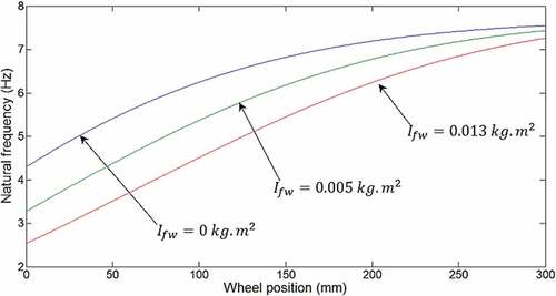
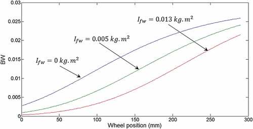
presents the absorber natural frequency (Hz) versus the displacement of the wheel for different values of the moment inertia of flywheel. During the experiments, the moment inertia of flywheel can be adjusted by changing flywheel with different moment of inertia. The obtained results show that natural frequency of the proposed ATVA increases with increasing the position of the wheel. Furthermore, increasing the moment inertia of flywheel increases the tunable frequency range. In addition, this parameter is more effective at low frequency range.
Figure 4. The natural frequencies of the proposed ATVA under different moment inertia of flywheel.
shows the normalized bandwidth as a function of the position of the wheel. It is seen that the higher the wheel position, the greater the normalized bandwidth. On the other hand, decreasing the moment inertia of flywheel improves the normalized bandwidth.
Figure 5. The normalized bandwidth of the proposed ATVA under different moment of inertia.
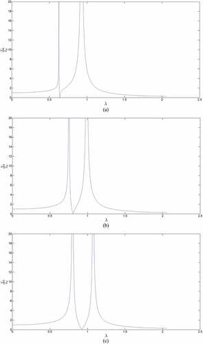
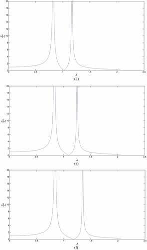
shows the transmissibility of the proposed ATVA. As shown in ), the antiresonance frequency of the system appears at about 3.94 Hz, and the antiresonance frequency slightly moves to higher frequency as the position of the wheel increases. Additionally, as shown in , once the wheel’s position is fixed, vibration attenuation occurs within a very narrow bandwidth (BW) in the vicinity of the antiresonance frequency. According to , BW can be highest when is highest, given a target transmissibility (
) of 0.1. Even for
and
, BW turns out to be only 2.4 percent. Thus, in the absence of an adaptive DVA, the system’s vibration attenuation performance can decline significantly in the presence of a modest shift in the excitation frequency.
Figure 6. The amplitude of vibration of primary structure at various wheel position. (a) , (b)
, (c)
, (d)
, (e)
, (f)
.
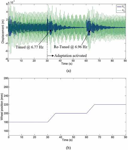
Numerical simulations are conducted on the closed-loop system consisted of the proposed tuned vibration absorber of Eqs. (3), (4), and (6), self-tuning algorithm, and the primary structure which is modeled as a single degree of freedom system. In the simulation, slight damping ratios are assumed. First, the ATVA is turned on with its transmission wheel initially positioned at 180 mm and at excitation frequency of 6.77 Hz, which is close to the natural frequency of primary structure. As shown in , the adaptation is activated after 30 s. The wheel position is automatically tuned toward 200 mm, at which the natural frequency of the ATVA matches the excitation frequency. The excitation frequency is then raised to 6.96, and it is seen that the wheel position is automatically re-tuned to 220 mm, at which the natural frequency matches the excitation frequency again.
Figure 7. Time response of the closed-loop system: (a) displacements of the primary structure and the absorber mass; (b) the wheel position.
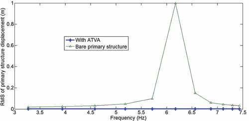
To evaluate the vibration attenuation performance of the proposed ATVA, a series of experiments are conducted. First, the frequency response of the primary structure without the ATVA attachment is obtained using an external excitation frequency change between 3.27 and 7.43 Hz. Then, the ATVA is appended to the primary structure and the self-tuning algorithm is enabled. Using the same frequency change scenarios, shows RMS values of the primary structure displacement with respect to excitation frequencies. As can be seen in , bare primary structure, the system has a large resonance peak at 6.177 Hz. However, in the presence of ATVA, vibration of the primary structure is significantly reduced over the operation range of frequencies.
Figure 8. Displacement RMS values of the primary structure with/without the ATVA at same excitation states.
6. Conclusions
In this study, a cone CVT was used in a DVA whose natural frequency could be tuned by means of adjusting the position of transmission wheel. The ATVA was used to mitigate the vibration of the structure in conjunction with a table-lookup algorithm. The numerical approach was used to test the proposed ATVA. The effect of ATVA parameters and z on the vibration suppression and absorber performance and broadband frequency is studied. The simulation results demonstrated that the structure vibration could be reduced effectively using the proposed ATVA rather than using passive-type absorbers for a wide frequency range. The acquired results can be utilized to guide the development of an appropriate ATVA. Future studies may incorporate a cone CVT into a pendulum-style vibration absorber. In this scheme, the pendulum will be directly coupled to the CVT gearbox to enable natural frequency tuning.
Acknowledgements
The author would like to thank the Faculty of Engineering, Naresuan University, for support and assistance with this research.
Disclosure statement
No potential conflict of interest was reported by the author.
Additional information
Funding
Notes on contributors
Surat Punyakaew
Surat Punyakaew received Ph.D. degree in mechatronics in 2020 from Asian Institute of Technology. He is currently work as a lecturer at Department of Mechanical Engineering, Naresuan University. His current research interests include the dynamics and control of robotic systems, adaptive control systems, vibration control, and ingenergy harvesting.
References
- Almashhor, A., & Asiri, S. A. (2021). Development of a new tuned vibration absorber based on one degree-of-freedom of translational motion. Cogent Engineering, 8(1), 1. https://doi.org/10.1080/23311916.2021.1976929
- Brennan, M. J. (1999). Actuators for active vibration control - Tunable resonant devices. Applied Mechanics and Engineering, 5(1), 63–13.
- Brzeski, P., Kapitaniak, T., & Perlikowski, P. (2015). Novel type of tuned mass damper with inerter which enables changes of inertance. Journal of Sound and Vibration, 349, 56–66. https://doi.org/10.1016/j.jsv.2015.03.035
- Brzeski, P., Lazarek, M., & Perlikowski, P. (2017). Experimental study of the novel tuned mass damper with inerter which enables changes of inertance. Journal of Sound and Vibration, 404, 47–57. https://doi.org/10.1016/j.jsv.2017.05.034
- Chung, J. T. (2004). Vibration absorber for reduction of the in-plane vibration in an optical diskdrive. IEEE Transactions on Consumer Electronics, 50(2), 552–557. https://doi.org/10.1109/TCE.2004.1309422
- Dong, X., Li, W., Yu, J., Pan, C., Xi, J., Zhou, Y., & Wang, X. (2020). Magneto-rheological variable stiffness and damping torsional vibration control of powertrain system. Frontiers inMaterials, 7, 121. https://doi.org/10.3389/fmats.2020.00121
- Frahm, H. (1909). Device for damped vibration of bodies. US Pat.
- Homaeinezhad, M. R., Yaqubi, S., & Gholyan, H. M. (2020). Control of MIMO mechanical systems interacting with actuators through viscoelastic linkages. Mechanism and Machine Theory, 147, 103763. https://doi.org/10.1016/j.mechmachtheory.2019.103763
- Hu, Y., & Chen, M. (2015). Performance evaluation for inerter-based dynamic vibration absorbers. International Journal of Mechanical Sciences, 99, 297–307. https://doi.org/10.1016/j.ijmecsci.2015.06.003
- Inman, D. J. (1994). Engineering vibration. Prentice–Hall.
- Jin, X., Chen, M. Z. Q., & Huang, Z. (2019). Suppressing random response of a regular structure by an inerter-based dynamic vibration absorber. Journal of Vibration and Acoustics, 141(4), 041004. https://doi.org/10.1115/1.4042934
- Kumbhar, S. B., Chavan, S. P., & Gawade, S. S. (2018). Adaptive tuned vibration absorber based on magnetorheological elastomer-shape memory alloy composite. Mechanical Systems and Signal Processing, 100, 208–223. https://doi.org/10.1016/j.ymssp.2017.07.027
- Mori, H., Mikhyeyev, O., Nagamine, T., Mori, M., & Sato, Y. (2010). Effect of a dynamic absorber on friction-induced vibration of a rectangular plate. Journal of Mechanical Science and Technology, 24(1), 93–96. https://doi.org/10.1007/s12206-009-1168-8
- Nguyen, X. B., Komatsuzaki, T., & Truong, H. T. (2020). Novel semiactive suspension using a magnetorheological elastomer (MRE)-based absorber and adaptive neural network controller for systems with input constraints. Mechanical Sciences, 11(2), 465–479. https://doi.org/10.5194/ms-11-465-2020
- Sadeghian, M. A., Yang, J., Wang, F., & Wang, X. (2022). Structural vibration control using novel adaptive tuned mass inertance damper (ATMID) with adjustable inertance. Applied Sciences, 12(8), 4028. https://doi.org/10.3390/app12084028
- Sun, J. Q., Jolly, M. R., & Norris, M. A. (1995). Passive, adaptive and active tuned vibration absorbers - a survey. Journal of Mechanical Design, 117(B), 234–242. https://doi.org/10.1115/1.2836462
- Viet, L. D., & Park, Y. (2011). Vibration control of the axisymmetric spherical pendulum by dynamic vibration absorber moving in radial direction. Journal of Mechanical Science and Technology, 25(7), 1703–1709. https://doi.org/10.1007/s12206-011-0418-8
- Von Flotow, A. H. (1994). Adaptive tuned vibration absorbers: Tuning laws, tracking agility, sizing and physical implementation. Proceedings of Noise-Con, 94, 81–101.
- Webster, A. C., & Vaicaitis, R. (1992). Application of tuned mass dampers to control vibrations of composite floor systems. Engineering Journal-American Institute of Steel Construction Inc, 29(3), 116–124.
- Wu, T. X. (2008). On the railway track dynamics with rail vibration absorber for noise reduction. Journal of Sound and Vibration, 309 (3–5), 739–755. https://doi.org/10.1016/j.jsv.2007.07.049
- Yuan, L., Sun, S., Pan, Z., Ding, D., Gienke, O., & Li, W. (2019). Mode coupling chatter suppression for robotic machining using semi-active magnetorheological elastomers absorber. Mechanical Systems and Signal Processing, 117, 221–237. https://doi.org/10.1016/j.ymssp.2018.07.051