
 ?Mathematical formulae have been encoded as MathML and are displayed in this HTML version using MathJax in order to improve their display. Uncheck the box to turn MathJax off. This feature requires Javascript. Click on a formula to zoom.
Abstract
Heat transfer devices have been employed in a wide range of industrial and home applications for heat conversion and recovery. Artificial roughness in the shape of repetitive ribs on a surface is a useful approach for improving heat transfer rates. The heat transfer and fluid flow properties of fully developed turbulent flow in a rectangular duct with repeated transverse semi-circular sectioned rib roughness on the absorber plate were investigated. A numerical solution has been done using fluent ANSYS 16 commercial software, and validation of result was carried out with Dittus–Boelter correlation. The numerical investigation of the thermal performance of a solar air heater was carried out at relative roughness pitch (between 7.14 and 17.86), Reynolds number (3800 and 18,000), heat flux (1000 W/m2), and constant relative roughness height (e/D = 0.042). For the analyzed range of parameters, it was found that the semi-circular transverse rib roughened duct with P/e = 10.71 and e/D = 0.042 provides the optimum thermo-hydraulic performance parameter. Within this optimum configuration, the maximum thermo-hydraulic performance parameter has been found to be 1.7328 at Reynolds number 15,000.
1. Introduction
Solar energy is abundant in nature and may be used as a source of energy to a large extent and is one of the most environmentally friendly types of renewable energy with the low efficiency. As a result, solar energy use for society has become one of the most important concerns among the world’s research community. The conversion, utilization, and recovery of energy all require a heat transfer process, making it critical to increase thermal performance. The solar air heater is a component that is used to heat the air and plays a vital role in energy conservation. Solar air heaters are one type of solar thermal system that is widely utilized for heating applications such as crop drying, space heating, winter home heating, and lumber seasoning (Gawande et al., Citation2016; Saini & Verma, Citation2008). The heat transfer coefficient between the heated absorber plate and the working medium, air, is low in solar air heaters, resulting in decreased efficiency. When artificial roughness with different geometry is added to the absorber plate, the efficiency of the solar air heater improves (Aharwal et al., Citation2008; R. Kumar et al., Citation2019). Artificial roughness penetrates the viscous sub-layer, increasing the intensity of turbulence in the duct and improving heat transmission from the roughened surface compared to a smooth surface (Gawande et al., Citation2016; Li et al., Citation2011; Yadav & Bhagoria, Citation2014). The artificial roughness, on the other hand, significantly increases frictional losses, requiring more energy to move the fluid through the duct. To limit the rise in friction losses, turbulence should be introduced only near the heat-transferring surface to break the viscous sub-layer and enhance heat transfer (Aharwal et al., Citation2008; Arun et al., Citation2021; Chang et al., Citation2008). Many scholars in the field of solar air heater research have proposed various artificial roughness geometries to improve heat transfer rate (Croce & D’Agaro, Citation2004; Jaurker et al., Citation2006; Luo et al., Citation2004; Maradiya et al., Citation2018). The use of repeated ribs on an absorber plate is one of the most practical and efficient ways to improve heat transfer. To assess the impact of artificial roughness on the thermal and hydraulic performance of the SAH duct, numerous experimental and computational fluid dynamics (CFD) studies have been conducted (Katoh et al., Citation2000; Singh & Singh, Citation2018; Yadav, Citation2013). Experimental and numerical convection heat transfer has been done in solar air heater with reverse L-shaped ribs (Gawande et al., Citation2016). In comparison to changes in relative roughness pitch (P/e) and Reynolds number, it has been reported that the presence of a reverse L-shaped rib has a considerable impact on heat transmission and friction factor properties. A thermo-hydraulic performance parameter (THPP) of 1.90 was reported for optimum roughness element design, considering heat transfer augmentation with the same pumping power (Gawande et al., Citation2016). The heat transfer and fluid flow characteristics of an SAH duct with transverse ribs of various cross-sections (square, semi-circular, and symmetric half NACA 0020 in both forward and reverse orientations) on one of its broad walls are investigated experimentally and numerically (S. Kumar et al., Citation2022). Maximum thermo-hydraulic performance parameter (THPP) was discovered for reverse NACA 0020 profiled ribs with e/D of 0.05, P/e of 12, and Reynolds number of 6000.
Patel et al. (Citation2020) determined the maximum thermo-hydraulic performance parameter (THPP) for reverse NACA 0040 profiled ribs with e/D of 0.065, P/e of 5, and Reynolds number of 6000. In their experiment, Patel et al. (Citation2021) used continuous and discontinuous NACA 0040 ribs and discovered a slight change in Nu and a considerable reduction in f.
The impact of rib configurations on heat transmission and frictional loss characteristics of a rib roughened solar air heater was investigated numerically and experimentally (Kumar & Kim, Citation2015; A. Kumar et al., Citation2012; Sharma & Kalamkar, Citation2017). The thermal and hydraulic performance of a solar air heater duct roughened with a non-uniform cross-sectioned square wave-profiled transverse rib was investigated using ANSYS Fluent (Singh & Singh, Citation2018; Choi et al., Citation2000). The relative roughness pitch 4–30 and Reynolds number 3000–15,000 have been used in the 3D research, with the relative roughness height set at 0.043. At a relative roughness pitch of 10 and a Reynolds number of 12,000, the highest thermo-hydraulic performance parameter was reported to be 1.43.
Singh et al. (Citation2019) presented the influence of two different numerous shaped ribs on heat transfer and friction factor characteristics using experimental and computational analyses. The maximum thermal enhancement for square wave-shaped ribs is 2.50 times, with a 3.92-times pumping power penalty was reported; however, the enhancements for multiple cracked ribs are 3.24 and 3.85 times, respectively.
The thermo-hydraulic response of a duct with an equilateral triangular cross section and V-down ribs with numerous gaps and turbulence promoters as artificial roughness was investigated (Misra et al., Citation2020). The study revealed that the highest heat transfer rate was achieved at (P/e) = 10 and P/e = 45, respectively, when the relative roughness pitch (P/e) is varied from 8 to 14 and the angle of attack is varied from 45° to 60°. Yadav and Bhagoria (Citation2013) have been investigated the impacts of transverse wire rib roughness with small diameter on heat transfer and fluid flow processes in solar air heaters using ANSYS FLUENT 2D CFD simulation. This study reported that the average Nusselt number and average friction factor rise as the relative roughness height increases and found a maximum value of thermal enhancement factor of 1.65. CFD simulations of heat transfer enhancement and flow characteristics due to artificial roughness in the form of ribs on a broad, heated wall of a rectangular duct for turbulent flow (Reynolds number range 3000–20,000, which is relevant in solar air heaters) were performed (Chaube et al., Citation2006). In contrast to a smooth surface, their results indicate a considerable increase in heat transfer. Aharwal et al. (Citation2008) were investigated heat transfer and friction factor properties of a rectangular duct roughened with repeated square cross-section split-ribs with a gap on one broad wall oriented at an inclination with relative to the direction of flow. They found that the greatest increase in Nusselt number and friction factor compared to the smooth duct was 2.59 and 2.87 times, respectively. For a relative gap width of 1.0 and a relative gap position of 0.25, the thermo-hydraulic performance parameter is found to be the maximum. García et al. (Citation2012) examined the thermo-hydraulic performance of three types of artificial roughness augmentation techniques: corrugated tubes, dimpled tubes, and wire coils in laminar, transitional, and turbulent regimes. The geometry of the artificial roughness has a bigger impact on pressure drop characteristics than on heat transfer enhancement, according to the findings (García et al., Citation2012). Skullong et al. (Citation2017) have been experimentally investigated heat transfer characteristics of wavy grooves integrated with pairs of trapezoidal-winglets (TW) installed on the absorber plate in a solar air heater duct within the range of Reynolds number 4500–22,000. The paper reported that TW alone provides significantly more heat transfer, but the groove provides significantly less pressure loss. The analysis revealed that when the TW is combined with the groove, it significantly increases heat transfer compared to a smooth channel and single devices functioning alone.
Solar water heater power is a component utilized for water heating. Solar-based water heater assumes a significant job inside the preservation of energy. Solar-based water heaters are recognized through their thermal productivity and that relies upon the elective energy transmission, conduction, and absorption of the working (water) liquid.
Yadav and Bhagoria (Citation2013) and Abhay et al. (Citation2018) used a 2D practical domain to investigate the effect of wire- and square-shaped rib on SAC thermal performance, respectively. 2D ANSYS numerical simulations are performed for flow through the solar air collector for relevant Reynolds number (Re) which ranges from 3800 to 18,000. The RNG k-turbulence model was employed, and operational parameters of e/D = 0.021 to 0.042 and P/e = 7.14 to 35.71 and the highest level of THPP (1.65) were discovered (Yadav & Bhagoria, Citation2013). The simulation findings according to Abhay et al. (Citation2018) demonstrated that the duct with roughened surface improves heat transfer and friction factor (fr) by 2.13 and 3.54 times, respectively, as compared to a smooth duct. At a Re of 15,000, the solar air collector with square-shaped rib roughness and P/e = 7.14 has a superior THPP of 1.45.
Apart from experimental work, computational fluid dynamics (CFD) has been proved to be one of the most effective tools for researching fluid flow phenomena and heat transport. CFD uses numerical analysis to solve mathematical EquationEquations [4](4)
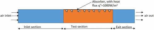
(4) . CFD works on the simple concept of dividing the entire system into small cells or grids and then computing the numerical solution of the system using discrete governing equations. The research above shows that adding artificial roughness on solar absorber has a significant effect in solar air heater, and very few CFD examinations on artificially roughened solar air heaters having different geometry transverse rib roughness have been conducted. According to the literature review, while many researchers have used different rib shapes in solar air heaters to increase performance, the use of semi-circular profile ribs in various orientations as artificial roughness in solar air heaters needs to be investigated further. The goal of this research is to conduct such a study and propose a numerical model for predicting heat transfer and flow friction in an artificially roughened solar air heater with semi-circular-sectioned transverse rib roughness, as shown in , as well as to determine the best rib configuration for equal pumping power. According to Yadav and Bhagoria (Citation2013) and Gawande et al. (Citation2016), calculations using a 2D flow model produce findings that are closer to measurements than calculations using 3D flow. 2D flow is thus used in this study to reduce computer memory and computational time.
Figure 1. Schematic of two-dimensional solution domain for CFD analysis.
2. CFD Analysis of solar air heater duct
The computational domain of an artificially roughened solar air heater as a rectangle in two dimensions, which is divided into three sections namely entry section (L1 = 245 mm), test section (L2 = 280 mm), and exit section (L3 = 115 mm), has been used as shown in . For this, duct aspect ratio (W/H) is kept as 5 by taking height of the duct as H = 20 mm and width W = 100 mm and hydraulic diameter of solar air heater duct is D = 33.33 mm. The rib is kept at a height of 1.4 mm to minimize the effects of fin and flow passage blocking (Yadav, Citation2015; Yadav & Bhagoria, Citation2013). The rib pitch to rip height ratio (P/e) is kept between 7.14 and 17.86, and a steady heat flux of 1000 W/m2 is applied to the top surface of the test section. According to the experimental research (Chaube et al., Citation2006; Yadav & Bhagoria, Citation2013), the Reynolds number between 3800 and 18,000 is most suited for an air heater.
The fluid dynamics and heat transfer modeling of the artificially roughened solar air heater are carried out using ANSYS FLUENT 16, a general-purpose CFD package. The next sub-sections go through the computational model and technique in further detail. To model a problem using CFD, the following assumptions are taken into account:
Incompressible, steady-state turbulent flow situations are investigated.
The fluid’s properties remain constant across the duct’s length as shown in .
Air was used as a working fluid with inlet ambient conditions (300 K).
At the interface of fluid and solid, there are no-slip conditions.
Table 1. Thermo-physical properties of air and aluminum absorber plate
2.1. Mesh generation
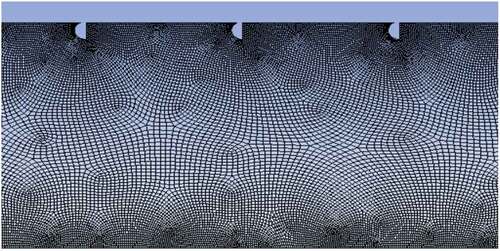
The meshing of the domain is done with ANSYS ICEM CFD v16. As illustrated in , a non-uniform mesh with a very fine mesh size is used to resolve the laminar sub-layer at near the solar air heater duct’s boundary which was generated on the computational domain of the solar air heater.
Figure 2. Non-uniform grid for computational domain of solar air heater with semi-circular ribs.
2.2. Boundary condition
The inlet flow to the duct is maintained by a uniform velocity inlet boundary condition, while the outlet flow is maintained by a pressure outlet boundary condition. At the input, a uniform air velocity is applied, while at the exit, a pressure outlet condition is applied with a fixed pressure of 1.013e5 Pa. Initially, the temperature of the air within the duct is assumed to be 300 K. The duct walls have been treated with impermeable boundary and no-slip wall condition. At the absorber plate (top wall), an uniform flux of 1000 W/m2 is supplied, while the bottom wall remains adiabatic and the physical parameters of the air are expected to remain constant at mean bulk temperature.
2.3. Numerical resolution
For the resolution of the mass, momentum, and energy equations, a CFD study based on the finite volume method was applied. The governing equation was discretized using the second-order upwind approach (Boulemtafes-Boukadoum & Benzaoui, Citation2014). The SIMPLE algorism was used to solve the governing equation between velocity and pressure, and Reynolds number was used to obtain the mean inlet velocity of the flow. For the momentum and turbulence equations, the convergence criterion was kept at 10−5, and for the energy equation, it was maintained at 10−9.
Continuity Equation:
Momentum equation
Energy equation
where are the molecular thermal diffusivity and turbulent thermal diffusivity, respectively, and are given by,
The RNG k-turbulence model with enhanced wall treatment produced the most precise findings. In previous CFD experiments published in the literature, the same model was utilized and declared to be the most appropriate (Gawande et al., Citation2016; Singh et al., Citation2019). The other relevant non-dimensional parameters of interest in the present CFD investigation are the Reynolds number, Nusselt number, friction factor, and thermal enhancement factor (F. p. Incropera, Citation2007; Yadav, Citation2013). The Reynolds number is defined as
The average Nusselt number for a solar air heater that has been artificially roughened is calculated by
where h is convective heat transfer coefficient. The average friction factor for a solar air heater with artificially roughened surfaces is calculated as follows:
where P is the pressure loss throughout the duct of a solar air heater that has been artificially roughened. It is important to note that the increase in heat transmission caused by artificial roughness is accompanied by a significant increase in friction losses. This leads to a significant increase in pumping expenses. As a result, any augmentation method must be examined in light of pumping expenses. The thermal enhancement factor, which is specified by the following equation, is a well-known method of such evaluation.
The value of this parameter must be greater than unity for the improvement system to be effective. The Nusselt number and friction factor for a solar air heater’s smooth duct may be calculated using the Dittus–Boelter equation (F. p. Incropera, Citation2007; Yadav, Citation2013).
All governing equations are discretized using a finite volume method and then solved in a segregated way using a second-order upwind-biased scheme. To simulate the heat transfer and fluid flow characteristics in the present numerical simulation, the RNG k– model was chosen as reported (Gawande et al., Citation2016; Yadav & Bhagoria, Citation2013). The following transport equations for the Renormalization group (RNG) k–
model provide the modeled turbulent kinetic energy, k, and its rate of dissipation. Transport equations used for Renormalization-group (RNG) k–e model, to determine turbulence kinetic energy, k and rate of dissipation,
, for computational domain analysis are
where represents the generation of turbulence kinetic energy due to mean velocity gradients and is expressed as
represents the effective turbulent viscosity and is given as,
The turbulent viscosity is computed by combining k and
as follows:
where = 0.0845 is constant. The quantities
and
are the inverse effective turbulent Prandtl numbers for k and
, respectively. The model constants have the following values,
= 1.42,
= 1.68,
= 1.39, and
= 1.39. The average heat transfer coefficient and pressure drop across the duct (P) are calculated using the area-weighted average method.
3. Results and discussion
3.1. Grid independence test
With a Re value of 12,000, roughness height (e = 1.4 mm), and relative pitch 7.14, a grid independence test is performed for different numbers of cells 195,263, 267,259, 384,321, 434.025, and 466,365. The difference in Nur and friction factor between 434.025 and 466,365 cells is quite minor. Percentage of variation in Nur has a minimal value (0.254%) for 434.025 and 466,365 as shown in , and for the remaining situations, 434,025 cells are employed for numerical simulation.
Table 2. Grid independence test for CFD analysis of Nusselt number
3.2. Validation of CFD model
Under identical conditions, the Dittus–Boelter correlation results confirm the CFD solution of the average Nusselt number and friction factor of a solar air heater absorber panel. The numerical results were found to be in good agreement with the Dittus–Boelter correlation results, with slight variation. For the Nusselt and friction factor values, the differences between the numerical results using the RNG k–e turbulence model and the Dittus–Boelter correlation are less than 4.7% as shown in .
Figure 3. Comparison of Nusselt number in CFD analysis and Dittus–Boelter correlation.

3.3. Average heat transfer characteristics
The addition of reverse semi-circular ribs as artificial roughness improves heat transfer compared to a smooth duct. represents the variation of the average Nusselt number as a function of Reynolds number for various values of relative roughness pitch (P/e) and a constant value of relative roughness height (e/D) 0.042. In all cases, the average Nusselt number rises in parallel with the Reynolds number, as expected. For a constant value of relative roughness height (e/D), the average Nusselt number increases with the decrease in relative roughness pitch (P/e). At Re = 15,000, the contour plots of velocity for various relative roughness pitches are given in . Increased turbulence caused by increased velocity causes vortices to form around rib.
Figure 4. The contour plots of velocity from CFD analysis for Re = 15,000 and at roughness pitch (a) P/e = 7.14, (b) P/e = 10.71, (c) P/e = 14.29, and (d), P/e = 17.86.
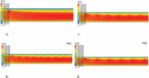
Figure 5. Variation of average Nusselt number for different values of relative roughness pitch and for fixed value of relative roughness height versus Reynolds number.
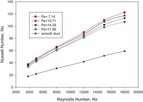
Increases in Reynolds number increase turbulence kinetic energy and turbulence dissipation rate, which leads to a rise in turbulence intensity and, as a result, an increase in the average Nusselt number. The thickness of the laminar sub-layer reduces as the Reynolds number rises, and the vortices that result from the roughness contribute locally to heat removal.
This enhances the heat transfer rate as compared to a flat surface. shows the variation of the average Nusselt number ratio (Nur/Nus) as a function of Reynolds number for various relative roughness pitch (P/e) and a fixed relative roughness height (e/D) of 0.042.
Table 3. Nusselt number and friction factor enhancement ration for various relative roughness pitch
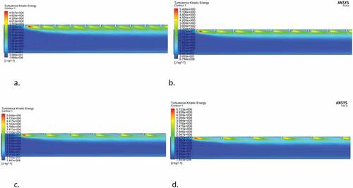
As demonstrated in , the average Nusselt number rises as the Reynolds number rises. With an increase in Reynolds number, the heat transfer rate increases due to an increase in velocity. As illustrated in the counter plot turbulent kinetic energy in , the semi-circular rib arrangement disturbs the development of the boundary layer and causes an increase in turbulent kinetic energy.
Figure 6. The contour plots of pressure at Re = 15,000 at relative roughness pitch of (a) P/e = 7.14, (b) P/e = 10.71, (c) P/e = 14.29, and (d) P/e = 17.86.
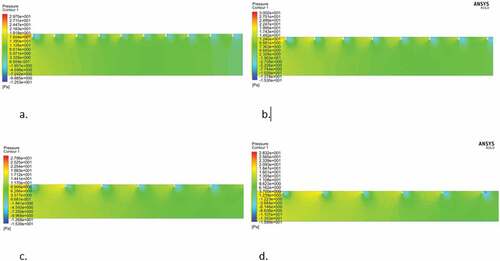
Figure 7. Variation of average friction factor for different values of relative roughness pitch and for fixed value of relative roughness height versus Reynolds number.
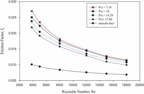
Figure 8. The contour plots of kinetic energy at Re = 15,000 at relative roughness pitch of (a) P/e = 7.14, (b) P/e =10.71, (c) P/e = 14.29, and (d) P/e = 17.86.
3.4. Average flow friction characteristics
shows the variation of average friction factor as a function of Reynolds number for various relative roughness pitch (P/e) and a fixed relative roughness height (e/D) of 0.42. In all conditions, the average friction factor reduces as the Reynolds number rises. For a constant value of relative roughness height (e/D), the average friction factor increases with decreasing in relative roughness pitch (P/e). The shedding of vortices from the semi-circular sectioned rib top results in an extra energy loss, resulting in a higher friction factor.
As the Reynolds number rises, the pressure gradient effects surrounding the rib decrease and the friction factor decreases. The contours in demonstrate that the air particles are more concentrated before the rib and more spaced out on the downstream side, indicating a bigger pressure decrease close to the rib. Because of the suppression of the viscous sub-layer, the average friction factor drops as the Reynolds number increases. For various values of relative roughness pitch (P/e) and a fixed value of relative roughness height (e/d) of 0.042, shows the variation of average friction factor ratio (fr/fs) as a function of Reynolds number. For the observed range of parameters, the highest increase in average friction factor is determined to be 2.47 times that of a smooth duct, corresponding to a relative roughness height of 0.042 and roughness pitch 7.14 at a Reynolds number of 5000.
3.5. Thermal enhancement factor
An increase in the Nusselt number and the friction factor is noticed when the relative roughness height increases. The rate of increasing of the friction factor is also observed to be faster than that of the Nusselt number. As a result, it is preferable to set the roughness geometry so that heat transfer is maximized while pumping losses are kept to a minimum. Thermo-hydraulic performance should be assessed simultaneously with thermal and hydraulic performance in order to analyze overall performance of solar air heater, and the thermal enhancement factor is a well-known way of such evaluation. For varying values of relative roughness pitch (P/e) and a fixed value of relative roughness height (e/D) of 0.042, demonstrates the fluctuation of the thermal enhancement factor with Reynolds number. shows the variation of the thermo-hydraulic performance parameter (THPP) with Reynolds number for various relative roughness pitch (P/e) values at constant relative roughness height (0.042). Within the parameters studied, the value of the thermal hydraulic
Figure 9. Variation of thermo-hydraulic performance parameter (THPP) with Reynolds number for different values of relative roughness pitch (P/e) at constant relative roughness height (e/D).
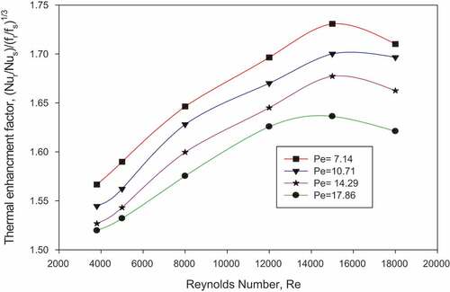
Performance parameter ranges from minimum value of 1.5037 to maximum value of 1.7328. The maximum heat transfer enhancement is observed at relative roughness pitch of 7.14 and Reynolds number of 15,000 in a CFD study of a solar air heater using a reverse semi-circular-shaped rib as artificial roughness, but the maximum value of average friction factor is observed at Reynolds number 3800. According to this study, a rib arrangement with a relative roughness pitch of 7.14 and a Reynolds number of 15,000 is the best configuration for maximizing heat transfer while minimizing friction losses.
According to a literature review (Gawande et al., Citation2016), roughened ducts with a relative roughness pitch of 6–10 had higher thermal hydraulic performance. According to the CFD simulation and findings, the maximum heat transfer enhancement is observed for P/e = 7.14, which is within the acceptable range.
4. Conclusion
Under the same operational conditions, artificially roughened solar air heaters have a higher rate of heat transfer than smooth solar air heaters. The parameters like flow Reynolds number (Re), relative roughness pitch (P/e), and relative roughness height (e/D) all affect the thermal enhancement factor of roughened solar air heaters.
For a fixed value of relative roughness height, the Nusselt number of roughened solar air heaters increases as flow Reynolds numbers and relative roughness pitch reduce.
However, for a fixed value of relative roughness height, the friction factor of a roughened solar air heater increases as flow Reynolds number decreases and relative roughness pitch reduces.
The CFD value of the thermal hydraulic performance parameter for semi-circular rib arrangement of solar air heater ranges between 1.502 and 1.7328.
At a Reynolds number of 15,000, a solar air heater roughened with semi-circular-sectioned transverse rib roughness on the absorber plate with P/e = 7.14 provides a superior thermal enhancement factor of 1.7328, and this can be used as an optimum condition for heat transfer augmentation.
Nomenclature
| = | equivalent or hydraulic diameter of duct, mm | |
| = | rib height | |
| = | heat transfer coefficient | |
| = | depth of the duct | |
| = | thermal conductivity of air, W/mK | |
| = | pitch, mm | |
| = | air temperature, K | |
| = | mean air flow velocity in the duct, m/s | |
| = | air flow velocity in x-direction, m/s | |
| = | air flow velocity in y-direction, m/s | |
| = | width of the duct | |
| = | pressure drop, Pa |
| = | Nusselt number for rough surface | |
| = | Nusselt number for smooth surface | |
| = | Prandtl number | |
| = | relative roughness pitch | |
| = | Reynolds number | |
| = | duct aspect ratio |
| Dimensionless parameters | ||
| = | relative roughness height, mm | |
| = | friction factor | |
| = | friction factor for rough surface | |
| = | friction factor for smooth surface | |
| = | Nusselt number | |
| Greek leters | ||
| = | dynamic viscosity, Ns/m2 | |
| = | turbulent viscosity, Ns/m2 | |
| = | density of air, Ns/m2 | |
| = | molecular thermal diffusivity | |
| = | turbulent thermal diffusivity | |
| b | = | ratio of orifice diameter to pipe diameter |
| e | = | dissipation rat |
Data Availability
The data used to support this study are included with in the article.
Disclosure statement
No potential conflict of interest was reported by the authors.
Additional information
Funding
References
- Abhay, L., Chandramohan, V. P., & Raju, V. R. K. (2018). Numerical analysis on solar air collector provided with artificial square shaped roughness for indirect type solar dryer. Journal of Cleaner Production, 190, 353–14. https://doi.org/10.1016/j.jclepro.2018.04.130
- Aharwal, K. R., Gandhi, B. K., & Saini, J. S. (2008). Experimental investigation on heat-transfer enhancement due to a gap in an inclined continuous rib arrangement in a rectangular duct of solar air heater. Renewable Energy, 33(4), 585–596. https://doi.org/10.1016/j.renene.2007.03.023
- Arun, M., Barik, D., Sridhar, K. P., & Vignesh, G. (2021). Experimental and CFD analysis of plain and dimples tube at application of solar water heater. Materials Today: Proceedings. 42, 804–809.
- Boulemtafes-Boukadoum, A., & Benzaoui, A. (2014). CFD based analysis of heat transfer enhancement in solar air heater provided with transverse rectangular ribs. Energy Procedia, 50, 761–772. https://doi.org/10.1016/j.egypro.2014.06.094
- Chang, S. W., Liou, T. M., Chiang, K. F., & Hong, G. F. (2008). Heat transfer and pressure drop in rectangular channel with compound roughness of V-shaped ribs and deepened scales. International Journal of Heat and Mass Transfer, 51(3–4), 457–468. https://doi.org/10.1016/j.ijheatmasstransfer.2007.05.010
- Chaube, A., Sahoo, P. K., & Solanki, S. C. (2006). Analysis of heat transfer augmentation and flow characteristics due to rib roughness over absorber plate of a solar air heater. Renewable Energy, 31(3), 317–331. https://doi.org/10.1016/j.renene.2005.01.012
- Choi, K. S., Katoh, K., & Azuma, T. (2000). Heat-transfer enhancement and pressure loss by surface roughness in turbulent channel flows. International Journal of Heat and Mass Transfer, 43, 4009–4017. https://doi.org/10.1016/S0017-9310(00)00033-8
- Croce, G., & D’Agaro, P. (2004). Numerical analysis of roughness effect on microtube heat transfer. Superlattices and Microstructures, 35(3–6), 601–616. https://doi.org/10.1016/j.spmi.2003.09.014
- F. p. Incropera. (2007). Fundamentals of heat and mass transfer.
- García, A., Solano, J., Vicente, P. G., Viedma, A. (2012). The influence of artificial roughness shape on heat transfer enhancement: Corrugated tubes, dimpled tubes and wire coils. 35, 196–201. https://doi.org/10.1016/j.applthermaleng.2011.10.030
- Gawande, V. B., Dhoble, A., Zodpe, D., & Sunil Chamoli. (2016). Experimental and CFD investigation of convection heat transfer in solar air heater with reverse L-shaped ribs. Solar Energy, 131, 275–295. http://dx.doi.org/10.1016/j.solener.2016.02.040
- Jaurker, A. R., Saini, J. S., & Gandhi, B. K. (2006). Heat transfer and friction characteristics of rectangular solar air heater duct using rib-grooved artificial roughness. Solar Energy, 80(8), 895–907. https://doi.org/10.1016/j.solener.2005.08.006
- Katoh, K., Choi, K.-S., Azuma, T. (2000). Heat-transfer enhancement and pressure loss by surface roughness in turbulent channel flows. International Journal of Heat and Mass Transfer, 43(21), 4009–4017. https://doi.org/10.1016/S0017-9310(00)00033-8
- Kumar, S., Das, R. K., & Kulkarni, K. (2022). Comparative study of solar air heater (SAH) roughened with transverse ribs of NACA 0020 in forward and reverse direction. Case Studies in Thermal Engineering, 34, 102015. https://doi.org/10.1016/j.csite.2022.102015
- Kumar, A., & Kim, M.-H. (2015). Convective heat transfer enhancement in solar air channels. Applied Thermal Engineering, 89(6), 239–261. https://doi.org/10.1016/j.applthermaleng.2015.06.015
- Kumar, R., Kumar, A., & Goel, V. J. R. E. (2019). Performance improvement and development of correlation for friction factor and heat transfer using computational fluid dynamics for ribbed triangular duct solar air heater. 131, 788–799. https://doi.org/10.1016/j.renene.2018.07.078
- Kumar, A., Saini, R. P., & Saini, J. S. (2012). Experimental investigation on heat transfer and fluid flow characteristics of air flow in a rectangular duct with multi v-shaped rib with gap roughness on the heated plate. Solar Energy, 86(6), 1733–1749. https://doi.org/10.1016/j.solener.2012.03.014
- Li, X.-W., Meng, J.-A., & Li, Z.-X. (2011). Roughness enhanced mechanism for turbulent convective heat transfer. International Journal of Heat and Mass Transfer, 54(9–10), 1775–1781. https://doi.org/10.1016/j.ijheatmasstransfer.2010.12.039
- Luo, D. D., Leung, C. W., & Chan, T. L. (2004). Forced convection and flow friction characteristics of air-cooled horizontal equilateral triangular ducts with ribbed internal surfaces. International Journal of Heat and Mass Transfer, 47(25), 5439–5450. https://doi.org/10.1016/j.ijheatmasstransfer.2004.07.003
- Maradiya, C., Vadher, J., & Agarwal, R. (2018). The heat transfer enhancement techniques and their thermal performance factor. Beni-Suef University Journal of Basic and Applied Sciences, 7(1), 1–21. https://doi.org/10.1016/j.bjbas.2017.10.001
- Misra, R., Singh, J., Jain, S. K., Faujdar, S., Agrawal, M., Mishra, A., & Goyal, P. K. (2020). Prediction of behavior of triangular solar air heater duct using V-down rib with multiple gaps and turbulence promoters as artificial roughness: A CFD analysis. International Journal of Heat and Mass Transfer, 162, 120376. https://doi.org/10.1016/j.ijheatmasstransfer.2020.120376
- Patel, Y. M., Jain, S. V., & Lakhera, V. J. (2020). Thermo-hydraulic performance analysis of a solar air heater roughened with reverse NACA profile ribs. Applied Thermal Engineering, 170, 114940. https://doi.org/10.1016/j.applthermaleng.2020.114940
- Patel, Y. M., Jain, S. V., & Lakhera, V. J. (2021). Thermo-hydraulic performance analysis of a solar air heater roughened with discrete reverse NACA profile ribs. International Journal of Thermal Sciences, 167, 107026. https://doi.org/10.1016/j.ijthermalsci.2021.107026
- Saini, R. P., & Verma, J. (2008). Heat transfer and friction factor correlations for a duct having dimple-shape artificial roughness for solar air heaters. Energy, 33(8), 1277–1287. https://doi.org/10.1016/j.energy.2008.02.017
- Sharma, S. K., & Kalamkar, V. R. (2017). Experimental and numerical investigation of forced convective heat transfer in solar air heater with thin ribs. Solar Energy, 147, 277–291. https://doi.org/10.1016/j.solener.2017.03.042
- Singh, I., & Singh, S. (2018). CFD analysis of solar air heater duct having square wave profiled transverse ribs as roughness elements. Solar Energy, 162, 442–453. https://doi.org/10.1016/j.solener.2018.01.019
- Singh, I., Vardhan, S., Singh, S., & Singh, A. (2019). Experimental and CFD analysis of solar air heater duct roughened with multiple broken transverse ribs: A comparative study. Solar Energy, 188, 519–532. https://doi.org/10.1016/j.solener.2019.06.022
- Skullong, S., Promvonge, P., Thianpong, C., Jayranaiwachira, N., & Pimsarn, M. (2017). Heat transfer augmentation in a solar air heater channel with combined winglets and wavy grooves on absorber plate. Applied Thermal Engineering, 122, 268–284. https://doi.org/10.1016/j.applthermaleng.2017.04.158
- Yadav, A. S. (2015). CFD investigation of effect of relative roughness height on Nusselt number and friction factor in an artificially roughened solar air heater. Journal of the Chinese Institute of Engineers, 38(4), 494–502. https://doi.org/10.1080/02533839.2014.998165
- Yadav, A. S., & Bhagoria, J. J. E. (2013). A CFD (computational fluid dynamics) based heat transfer and fluid flow analysis of a solar air heater provided with circular transverse wire rib roughness on the absorber plate. 55, 1127–1142. https://doi.org/10.1016/j.energy.2013.03.066
- Yadav, A. S., & Bhagoria, J. L. (2014). A numerical investigation of square sectioned transverse rib roughened solar air heater. International Journal of Thermal Sciences, 79, 111–131. https://doi.org/10.1016/j.ijthermalsci.2014.01.008