
 ?Mathematical formulae have been encoded as MathML and are displayed in this HTML version using MathJax in order to improve their display. Uncheck the box to turn MathJax off. This feature requires Javascript. Click on a formula to zoom.
Abstract
The effects of flame speed and explosion pressure on the flame-quenching performance of an in-line crimped-ribbon flame arrester was investigated using propane, ethylene, and hydrogen/air mixtures. The results show that the in-line arrester successfully stopped flames moving at high speeds and generating low explosion pressures, independently of pipe length and ignition distances, but failed for flames moving at low speeds and generating high explosion pressures. This indicates that both flame speed and explosion pressure are key parameters to evaluate the efficiency of an in-line flame arrester. Thus, the effect of increased pressure should be considered when the maximum flameproof speed by a given crimped-ribbon arrester is obtained. Furthermore, the relationship between the flameproof speed and explosion pressure is presented, based on the physical model of heat conduction, which is proved by experiments and provides more accurate reference for design and selection of crimped-ribbon flame arrester.
PUBLIC INTEREST STATEMENT
Modern industry is developing rapidly, thus, research on prevention and suppression of gas explosion of industrial medium has become an academic frontier project. Therefore, studying the suppression of combustion and explosion of flammable gas in pipelines is an important subject in safety technology. A flame arrester is a device permeable to gas flow that can both quench a flame and its combustion products sufficiently to prevent reignition at the arrester outlet. In recent years, flame arresters, especially the crimped-ribbon type, have been widely used in the petrochemical and natural gas industries.
However, relevant experiments and theoretical research have been conducted and a certain degree of progress has been achieved, the work in this field remains insufficient. One reason is that a quenching failure occurred during practical application although these arresters were approved and qualified by the standard ISO 16852-2016. Consequently, dangerous accidents such as explosions tend to occur. It indicates that the flame is influenced by many factors when it passes through the flame arrester.
The present study aims to obtain further experimental data and investigate flame arrester performance through analyzing the flame speed, and explosion pressure change rule by considering the condition of the same ignition distance and different ignition positions and vice versa. The influence of the arrester performance on the flame propagation energy characterized by the flame speed and the explosion pressure is analyzed. Then, this study presents the flameproof speed calculation method for the stoppage of various fuel/air mixture deflagrations by crimped-ribbon flame arresters.
1. Introduction
Flame arresters are broadly divided into two major types: deflagration and detonation flame arresters. Another parameter for selecting a flame arrester is directionality, which refers to the direction of the flame approach for which an arrester is designed to operate in a pipeline. The pipeline connected to the flame arrester with an identified ignition source is the “unprotected side” of the arrester. The pipeline connected to the arrester with at-risk equipment (equipment that must be protected from the temperature or pressure associated with flame penetration) is the “protected side.” If a flame arrester may encounter a flame arriving from only one direction, a “unidirectional” arrester can be used. If a flame may arrive from either direction, a “bidirectional” flame arrester is needed. The latter arrester is either symmetrically constructed or has been tested and certified for deflagrations and detonations approaching from either direction. Crimped ribbon flame arresters are usually installed in the pipelines carrying flammable gases or on the top of storage tanks containing flammable liquids. They allow the flammable gas to pass through but prevent the propagation of a flame. Improper design of flame arresters may give rise to flameproof failure, which can result in a fire or an explosion and lead to a great loss of lives and property. (Asano et al., Citation2010; Bao et al., Citation2021; Beauvais et al., Citation1994; Britton, Citation2000; Desai, Citation1996; Grossel, Citation2002; Henkel et al., Citation2019; Howard, Citation1982, Citation1988; Kakutkina et al., Citation2009; Kawashima et al., Citation2007; Lietze, Citation1995, Citation2002; Lin et al., Citation2022; Okawa et al., Citation2012; Popp & Baum, Citation1997; Wang et al., Citation2017).
Wilson and Attalah (Citation1975) have summarized the findings of 14 studies on crimped ribbon, metal foam, tube bundles, perforated blocks, gravel beds, and parallel plates. The best flame quenching performance for the least pressure drop was offered by arresters of the crimped ribbon type; gravel beds and metal foam were also very effective, but they had relatively large pressure drops and were subject to blockage. For high-speed flames, which are usually accompanied by a pressure rise, an array of apertures must have sufficient pressure drop to decelerate the flame, and sufficient length to achieve the heat loss needed to quench the flame. Thus, the diameter criterion is not sufficient, and the effective length of the passageway must have connections.
The flame can be quenched when the flame velocity is low; however, a high-speed flame can break down the arrester. An experiment conducted by (Heidermann & Davies, Citation2006) showed that the flame velocity and explosion pressure obtained in a closed pipe was the highest; tests at the open end showed the lowest propagation velocity and explosion pressure.
Specifications of flame arresters vary according to the fuel properties and nature of the application (Beauvais et al., Citation1994). The working mechanism of the flame arresters is based on absorbing the heat of a flame, while it passes through the small channels. The channel dimensions required to extinguish the flame are known as the Maximum Experimental Safety Gap (MESG; Britton, Citation2000). An experiment conducted by Wang et al. (Citation2017) showed that the expansion ratio, the length of the narrow channel, and the cross-section of the narrow passage are the three dominant factors that influence the flameproof velocity. Based on this analysis, the relation between the flameproof velocity and the expansion ratio, the thickness of the crimped ribbon element and the cross-section of the narrow passage were presented. The flame speed and the explosion pressure change rule by considering the physical properties of arrester analyzed by Sun et al. (Citation2017) indicated that the quenching mechanism for gases with different MESG values is related to the porosity and thickness of the arrester element, as well as L/D aspect ratio of the pipe.
Although relevant experiments and theoretical research have been conducted and a certain degree of progress has been achieved, the work in this field remains insufficient. One reason is that quenching failures have been observed multiple times in the field. Even though these arresters were approved and qualified by the standard ISO 16852–2016. It indicates that the other factors than flame speed are in play when the flame passes through the in-line flame arrester. One important aspect to consider is that the flame propagation process in the pipe is accompanied by a variation in flow field pressure. Consequently, the flame arrester can be subject to a slight overpressure, which is the result of the interaction between the pressure waves and the flame. To obtain agreement with the performance for an arrester mounted in a pipeline with the increased explosion pressure, it is necessary to investigate the further relationship between the flameproof speed and the explosion pressure.
This study conducted propane/air, ethylene/air, and hydrogen/air deflagration quenching experiments with crimped-ribbon flame arresters in different test conditions based on a high-precision experimental system. The objective of the present study was to obtain further experimental data and investigate flame arrester performance through analyzing the flame speed, and explosion pressure change rule by considering the condition of the same ignition distance and different ignition positions and vice versa. The influence of the arrester performance on the flame propagation energy characterized by the flame speed and the explosion pressure was analyzed. The last part of this study presents the flameproof speed calculation method for the stoppage of various fuel/air mixture deflagrations by crimped-ribbon flame arresters.
2. Experimental apparatus and procedure
2.1. Tube configuration
The experimental system mainly consisted of a piping configuration, a gas mixing equipment, a sensor detection system, and a data acquisition device. The experimental device and schematic diagram are shown in . (Sun et al., Citation2017). The tests were completed based on the experimental schemes of Cases A, B, and C, which is shown in . The flame arrester was a crimped-ribbon in-line flame arrester with an 80-mm nominal diameter. The pipe was connected to the arrester and has the same diameter D = 80 mm. The different values of the flame speed and the pressure at the test point were obtained when the ignition distance was 40D or 50D; the pipe length L1 on the ignition side was 50D and 40D, respectively (see, ). Owing to the various positions of the in-line crimped ribbon flame arresters, for example, connected to burners, flare stacks, and on both ends of enclosed equipment, and according to the requirements of ISO 16852–2016, both, the ignition end on the left side of the pipe and the closed end on the right side were flanged in this experiment. The pipe material was seamless steel, and the wall thickness was 4.5 mm. Ignition was achieved by a spark plug mounted at the center of the left flange; the ignition energy was approximately 10 mJ.
Figure 1. The explosion pipe picture.
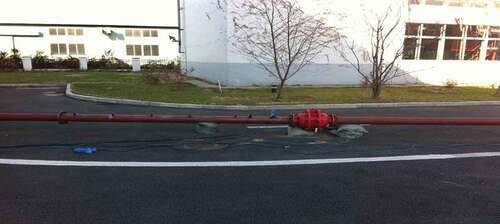
Figure 2. The experimental system structure diagram.
Figure 3. The experimental schemes of Cases A, B, and C.
Table 1. Experimental conditions
2.2. Gas mixing equipment
The gas mixing equipment fulfilled the requirements of gas mixing in the static volumetric method and the dynamic volumetric method. The maximum error of the static gas mixing was 0.1% and the flow rate was not less than 1 m3/min; the maximum error of the dynamic gas mixing was 0.2%, as required. The gas was injected into the system through the manifolds with a design pressure of 15 MPa (4 bottles). The manifolds were supplied with eight sets of crossover subs with which different feed gases could be exchanged. The system was also composed of a flow controller, a pressure relief device, and pressure gauges. The manifolds were connected by a hose to the outdoor steel bottles and vent pipe. For safety, the pipelines could be purged with nitrogen, or could be nitrogen and vacuum protected through the nitrogen purging, venting, and vacuum system. The initial pressure for the experiment was atmospheric. Based on IEC 60079–0 and ISO 16852 standards, three typical gases (propane, ethylene, and hydrogen) were used as media at 4.2, 6.6, and 28.5 vol.%, respectively, according to MESG and MICR values. The purity of propane was higher than 96%, and the purity of ethylene and hydrogen was 99.98%.
2.3. Sensor detection system
The sensor detection system mainly consisted of a pressure transducer and flame detectors. According to the requirements of ISO 16852, the pressure was measured by a pressure transducer fitted to the unprotected side of the pipe. The pipe length “a” as shown in should not be more than 2D (± 10%, max. ± 50 mm) and not more than 250 mm.
The flame speed was measured by two flame detectors and fitted to the pipe on the unprotected side. The distance “b” between the two flame detectors as shown in should not be more than 3D. For detecting the flame we used spark plugs with high voltage potential between the two electrodes. When the flame passed, the spark plug the potential equation changed. The time was recorded when the flame passed the sensor. Knowing the distance between two sensors, we could calculate the average speed of the flame front between these two sensors.
A flame transmission through the flame arrester was indicated by a flame detector on the protected side. Furthermore, the voltage signals were used for both the pressure transducer and flame detectors because a quick response was needed; the range of the pressure transducer was 0–5 V, and that of the flame detector was 0–12 V. The accuracy of the pressure transducer was 0.25%, and the pressure response frequency was 200 KHz.
2.4. Data acquisition device
The data acquisition device was based on the National Instruments High-performance PCI Extensions for Instrumentation Express platform supported by data acquisition cards with high accuracy and isolation function. In this way, the correct acquisition could be performed for the signals, such as pressure, temperature, strain, voltage, and current, and the system safety, was ensured at the same time. The connection measurement and storage of control hardware, analysis data, displayed results, and data could be completed under the NI LabVIEW graphic programming environment to establish the appropriate system for testing and measurement. A remote controller was used as a system controller to ensure the safety of the experiment site. The PXI Express measuring system could be controlled by a PC with the remote controller connected through an optical fiber. The optical fiber could extend to 100 m to achieve electric isolation between the PXI Express measuring hardware and the PC. The sampling rate per channel for the data acquisition device was 2 Mb/s.
2.5. Test procedure
The tests were conducted at the Shenyang Institute of Special Equipment Inspection and Research in China. The gas mixing equipment was used to prepare the premixed gas at a given concentration in the experimental pipe with the dynamic volumetric method. The gas analyzer was then used to acquire the concentration of flammable gas after the premixed gas was mixed evenly. When the experimental conditions were satisfied, the ignition and real-time data acquisition started. The experiment data were stored upon completion of the experiment. The experimental procedure also covered the following steps: opening the flanges on both ends of the pipe, venting the exhaust gas produced in the explosion process, installing the flanges, checking the air tightness of the pipe, and preparing for the next experiment.
3. Results and discussion
The test is completed based on the experimental schemes of Cases A, B, and C. The results of the flame propagation for three cases were obtained by changing the relation between the pipe length and the position of the ignition point. The effect of flame speed and explosion pressure on the arrester performance were analyzed.
Experiments were run two times for each gas mixture; the values of the flame speed and the pressure were recorded. The results obtained with the crimped-ribbon arresters are summarized in . In Case A, the arrester fails to stop the flame; in Cases B and C, the arrester successfully stops the flame. Thus, under the condition of the same ignition distance and different ignition positions, or the same pipe length and different ignition distances, the arrester successfully stops the flame at high flame speed and low explosion pressure, whereas it fails to stop the flame at low flame speed and high explosion pressure. These findings indicate a highly important experimental phenomenon.
Figure 4. Flame speed results for various gases.
Figure 5. Explosion pressure results for various gases.
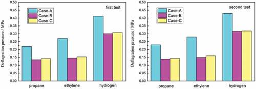
We consider the first propane experiment test as an example. The signals of each sensor show that the flame speed is 67.1 m•s−1 as the flame arrives at the test point, and the explosion pressure at the test point is 0.22 MPa in Case A. The flame signals at the front end of the arrester in Case A are shown in ), and the signal behind the arrester is shown in ). For Case B, the flame speed is 82.3 m•s−1 and the explosion pressure is 0.135 MPa. For Case C, the flame speed is 88.4 m•s−1 and the explosion pressure is 0.142 MPa. The flame signals on the front-end of the arrester in Cases B or C are shown in ), and the signal behind the arrester is shown in ).
Figure 6. Flame detector signals.
As shown in ), in Case A, the flame detector on the front-end of the arrester acquires two oscillations, while the flame detector behind the arrester detects one signal. Therefore, the flame front fluctuates at this test point, i.e., the flame is not quenched when it contacts the arrester element. As shown in Figures ), in Case B or C, the flame detector on the front-end of the arrester acquires one oscillation, while the flame detector behind the arrester does not detect the signal. Therefore, the flame front does not fluctuate at this test point, i.e., the flame is quenched at the arrester element.
During the three experiments, the overpressure fluctuates obviously. The explosion pressure curves for the first propane experiment in Case A are illustrated in ). Cases B or C are shown in ). Experimental results show that there are several peaks of pressure signal, and the peak value increases gradually and then decreases to a negative pressure. This finding indicates that the combustion process is continuous, several types of pressure waves overlap, and a short-term negative pressure exists inside the pipe at the end of the combustion.
Figure 7. Pressure transducer signals.
The experimental results show that the flame propagation process in the pipe is accompanied by a variation in flow field pressure; the apparent feature is the oscillation of the flame and pressure wave. Furthermore, the flame propagation energy characterized by the flameproof speed and the explosion pressure is the key to successfully stopping the flame. However, the flameproof speed is not the only criterion for successfully stopping the flame; the explosion pressure is also an important contributor. Thus, certain relationship may exist between them. In some cases, the resulting overpressure was neglected, which was a reasonable assumption for the cases considered since explosions occurred in a straight narrow pipe without obstructions. However, in the present experiments with ignition at the closed end of the pipe, the explosion pressure rose significantly above atmospheric pressure, which means that some additional considerations are needed to quantify the effect of increased pressure on the performance of the flame arresters (Sun et al., Citation2017).
For crimped-ribbon arresters, an equation for the maximum flameproof speed was obtained by Zhou et al. (Citation1997). It was shown that the relationship between the size of the crimp and the speed of the flame that was just quenched by the arrester could be represented by:
Where is flameproof speed,
stands for gas coefficient of kinematic viscosity in the narrow parallel plate channel,
is Prandtl number.
and
are arrester thickness and arrester crimp height size, respectively.
is boundary layer thickness ratio when the flame is quenched, A= δq/δT. δq and δT are the quench boundary layer thickness and the thermal boundary layer thickness respectively.
stands for the ratio of boundary layer thickness after the flame is extinguished when the hot gas continues to propagate for a certain length in the arrester.
In Equationequation (1)(1)
(1) ,
is related to the flame adiabatic flame temperature
, the flame-quenching temperature
and the wall temperature
.
is related to the warm air flow temperature
, the minimum ignition temperature for combustible gas
and the wall temperature
. Thus, the heat loss of combustion flame is related to these parameters.
Previous studies from Palmer and Tonkin (Citation1963) have shown that the heat to be abstracted from the unit volume of the flame to quench it should be approximately proportional to the pressure. That means if the pressure of the unburnt gas mixture is raised, the heat released upon combustion of the unit volume of the mixture is also raised proportionately, but the flame volume stays approximately constant because the flame temperature and the dissociation of the product molecules change minimally with pressure over the range in question. Thus, the heat to be extracted from the unit volume of the flame to quench it should be roughly proportional to the pressure.
However, in the present experiments with ignition at the closed end of the pipe, the explosion pressure rose appreciably above atmospheric pressure, and so Equationequation (1)(1)
(1) needed to be modified to quantify the effect of increased pressure on the performance of the flame arresters. Hence, Equationequation (1)
(1)
(1) should become:
The above partial values from different publications (Turns, Citation2012; Wark & Richards, Citation1999) summarized in were taken for the properties of the propane, ethylene, and hydrogen flames; hence, Equationequation (2)(2)
(2) for different flames could be represented:
Table 2. Calculating parameters for flame speed
Propane-air mixture:
Ethylene-air mixture:
Hydrogen-air mixture:
Since a flame arrester is essentially a heat exchanger, an attempt was made to investigate the ethylene arresters with 0.5 mm crimp height to see if it could be possible to extinguish a deflagration propagating in an ethylene/air mixture in D = 80 mm pipe with different L/D ratio. The results are plotted in , which includes the conditions “flame stopped by arrester” and “flame passed through arrester”. EquationEquation (4)(4)
(4) is represented in by a straight line. In theory, the points for the condition “the arrester stopped the flame” should lie below the line and the points for the condition “the arrester failed to stop the flame” should lie above the line. Most of the points lie in fact on the predicted sides of the lines in , indicating that Equationequation (4)
(4)
(4) is in a reasonable agreement with the results obtained using the test pipeline. In general, the maximum relative error of the formula is only 10.9%, so it can be considered that the calculated results are reasonable. This result is also significant for propane and hydrogen, shown in .
Figure 8. Experiment results for ethylene-air explosion by arresters at different flame speed; the curve is drawn from equation (4).
Figure 9. Experiment results for propane-air explosion by arresters at different flame speed; the curve is drawn from equation (3).
Figure 10. Experiment results for hydrogen-air explosion by arresters at different flame speed; the curve is drawn from equation (5).
Hence, the theoretical relation previously found between the performance and the structure of arresters in Equationequation (3)(3)
(3) –(Equation5
(5)
(5) ) is in reasonable agreement with the results for the crimped arresters. This will provide theoretical and laboratorial references for deflagration quenching and design of in-line crimped-ribbon flame arresters.
4. Conclusion
This study investigated the deflagration flame propagation and quenching phenomenon of various fuel/air premixed gases through a crimped-ribbon flame arrester. The results show that both the explosion pressure and the flame speed are the important parameters for the performance of the flame arrester. The main findings are as follows:
(i) Results show that the in-line arrester successfully stopped the flame at high flame speed and low explosion pressure but failed at low flame speed and high explosion pressure.
(ii) Not only the flameproof speed, but also the explosion pressure is key to a successful quench of the flame. Therefore, it is necessary to have the experiment conditions unified to evaluate the performance of the flame arresters.
(iii) The relationship between flameproof speed and explosion pressure is presented, based on the physical model of heat conduction. This model considers the effect of increased pressure on the performance of the flame arresters. The findings indicate that the equations were in reasonable agreement with experimental results.
Acknowledgements
This work is supported by State Administration for Market Regulation Scientific Project (2021MK133).
Disclosure statement
No potential conflict of interest was reported by the author(s).
Additional information
Funding
Notes on contributors
Shaochen Sun
The research team focuses on the safety of petrochemical, chemical, biopharmaceutical, mining, and other industrial productions field. The characteristics of typical industrial fires and explosion accidents, the industrial disaster accidents, the theoretical models of disaster processes and hazard analysis simulations, the process hazard characteristics, the equipment and safety control technologies were studied. Based on the theory of explosion mechanics, combustion, thermodynamics, and kinetic theory of gases, theoretical analysis experimental research and numerical simulation are combined to analyze the explosion process.
The team has been engaged in the theoretical and experimental research of the deflagration flame propagation and quenching process in in-line crimped-ribbon flame arrester. The research in this paper is focused on the effect of flame speed and explosion pressure on flame quenching performance and the flameproof speed calculation method for the stoppage of various fuel/air mixture deflagrations by crimped-ribbon flame arresters.
References
- Asano, S., Ikeda, S., Kagawa, T., & Youn, C. (2010). Visualization of behaviors of a propagating flame quenching for hydrogen–air gas mixture. Journal of Visualization, 13(2), 107–12. https://doi.org/10.1007/s12650-009-0002-9
- Bao, L., Wang, P., Dang, W., Kuang, C., & Yu, A. (2021). Experimental study on detonation flame penetrating through flame arrester. Journal of Loss Prevention in the Process Industries, 72, 104529. https://doi.org/10.1016/j.jlp.2021.104529
- Beauvais, R., Mayinger, F., & Strube, G. (1994). Turbulent flame acceleration-mechanisms and significance for safety considerations. International Journal of Hydrogen Energy, 19(8), 701–708. https://doi.org/10.1016/0360-3199(94)90158-9
- Britton, L. G. (2000). Using maximum experimental safe gap to select flame arresters. Process Safety Progress, 19(3), 140–145. https://doi.org/10.1002/prs.680190304
- Desai, V. M. (1996). A flare deflagration incident at Rohm and Haas. Process Safety Progress, 15(3), 166–167. https://doi.org/10.1002/prs.680150310
- Grossel, S. S. (2002). Deflagration and detonation flame arresters (Chapter 5). American Institute of Chemical Engineers.
- Heidermann, T., & Davies, M., 2006. In-line flame arrester application limits and matrix concept for process plant safety from flash back of thermal combustion units. In:Proceedings of the Proc 40th Annual Loss Prevention Symposium, Global Congress on Process Safety AIChE Spring National Meeting, Orlando, FL, Wiley Subscription Services, Inc. 353–378.
- Henkel, S., Zakel, S., & Stolpe, F. (2019). Determination of the performance limits of flame arresters at increased oxygen concentrations. Journal of Loss Prevention in the Process Industries, 58, 17–21. https://doi.org/10.1016/j.jlp.2019.01.003
- Howard, W. B. (1982). Flame arresters and flashback preventers. Plant/Operations Progress, 1(4), 203–208. https://doi.org/10.1002/prsb.720010403
- Howard, W. B. (1988). Process safety technology and the responsibility of industry. Chemical Engineering Progress, 84(9), 25–33 https://www.researchgate.net/publication/283144311_Process_safety_technology_and_the_responsibility_of_industry.
- Kakutkina, N., Korzhavin, A., & Rychkov, A. (2009). Burning-through of porous flame arresters with a channel flame-arrester element. Combustion, Explosion, and Shock Waves, 45(3), 266–273. https://doi.org/10.1007/s10573-009-0035-3
- Kawashima, K., Youn, C., & Kagawa, T. (2007). Development of a nozzle-flapper-type servo valve using a slit structure. Journal of Fluids Engineering, 129(5), 573–578. https://doi.org/10.1115/1.2717617
- Lietze, D. (1995). Limit of safety against flame transmission for sintered metal flame arrester elements in the case of flashback in fuel gas/oxygen mixtures. Journal of Loss Prevention in the Process Industries, 8(6), 325–329. https://doi.org/10.1016/0950-4230(95)00033-X
- Lietze, D. (2002). Crimped metal ribbon flame arrestors for the protection of gas measurement systems. Journal of Loss Prevention in the Process Industries, 15(1), 29–35. https://doi.org/10.1016/S0950-4230(01)00010-9
- Lin, C. D., Cao, X. Y., Wang, Z. R., Wei, J. S., & Xu, J. J. (2022). Research on quenching performance and multi-factor influence law of hydrogen crimped-ribbon flame arrester using response surface methodology. Fuel, 326(15), 124911. https://doi.org/10.1016/j.fuel.2022.124911
- Okawa, Y., Youn, C., & Kagawa, T. (2012). A study of the characteristics of flow rate and extinction in a flame arrester with radial slit structure. Journal of Loss Prevention in the Process Industries, 25(2), 242–249. https://doi.org/10.1016/j.jlp.2011.10.008
- Palmer, K. N., & Tonkin, P. S. (1963). The quenching of propane–air explosions by crimped-ribbon flame arresters. In proceedings of the IChemE Symposium (pp. 15–20). Institution of Chemical Engineers.
- Popp, P., & Baum, M. (1997). Analysis of wall heat fluxes, reaction mechanisms, and unburnt hydrocarbons during the head-on quenching of a laminar methane flame. Combustion and Flame, 108(3), 327–348. https://doi.org/10.1016/S0010-2180(96)00144-7
- Sun, S. C., Liu, G., Liu, J. X., Ye, C., Ren, J. J., & Bi, M. S. (2017). Effect of porosity and element thickness on flame quenching for in-line crimped-ribbon flame arresters. Journal of Loss Prevention in the Process Industries, 50, 221–228. https://doi.org/10.1016/j.jlp.2017.09.017
- Turns, S. R. (2012). An introduction to combustion:Concepts and applications. McGraw-Hill Education.
- Wang, L. Q., Ma, H. H., Shen, Z. W., & Li, X. J. (2017). Quenching of crimped ribbon deflagration arrestor by propane-air premixed flame. Explosion and Shock Waves, 37(4), 766–772 https://doi.org/10.11883/1001-1455(2017)04-0766-07.
- Wark, K., & Richards, D. E. (1999). Thermodynamics. McGraw-Hill Publishing Company.
- Wilson, R. P., & Attalah, S. 1975. Design Criteria for Flame Control Devices for Cargo Venting Systems. U.S. Coast Guard Report CG-D-175-75. Department of Transportation.
- Zhou, K. Y., Li, Z. F., & Zhou, Z. L. (1997). The quenching of deflagration by crimped-ribbon flame arresters. Journal of China University of Science and Technology, 27(4), 449–454.