
 ?Mathematical formulae have been encoded as MathML and are displayed in this HTML version using MathJax in order to improve their display. Uncheck the box to turn MathJax off. This feature requires Javascript. Click on a formula to zoom.
Abstract
The paper presents a CFD investigation of the effect of the inlet and outlet angles on the flow performance of the ferrolfuidic magnetic mircropump. The methodology employed is based on treating the overall flow path in the inlet or outlet chambers as a series connected network, and calculating the pressure loss in the inlet and outlet at various angles by subtracting the total pressure loss in the flow path from the known pressure losses in the other items in the path. CFD simulations employed in this study include first-order and second-order momentum schemes as well as simple and couple momentum schemes. The simulation shows that a gentler inlet and outlet angles reduce the inlet and outlet pressure loss coefficients, leading to a significant drop in the torque and power needed to drive the pump, and a significant improvement in its mechanical efficiency. For a pump with typical geometric and operating conditions, reducing the inlet angle from 90° to 0° causes the inlet pressure loss coefficient to drop by 80%, while a similar reduction in the outlet angle would drop the outlet pressure loss coefficient by almost 50%. This leads to a 5.4% rise in the mechanical efficiency of the pump. Further, an increased pressure loss coefficient at sharp inlet and outlet angles compromises pump’s applicability to higher pressure application as it causes the loss of magnetic coupling between the external drivers and the driven pistons.
PUBLIC INTEREST STATEMENT
The paper presents a CFD investigation of the effect of the inlet and outlet angles, and
on the performance of the ferrofluidic mangetic micropump (FMM). The FMM provides a number of advantages particularly in particle-laden and stress-sensitive pumping application. This work was motivated by the observation that the values
and
in almost all of the FMM designs presented in the literature is 90°. This results in large changes in the direction of flow at the inlet and the outlet and comes in contrast with the recommended practice in flow designs, which calls for streamlined flow path with minimum changes in flow direction. CFD simulations show that for a pump with typical design parameters, reducing
and
from 90° to 0° leads to a 5.4% rise in the mechanical efficiency, and allows the pump to work in more demanding pressure head application, which may cause magnetic slippage.
1. Introduction
Micropumps are enabling microfluidic devices capable of transferring fractions of milliliters of liquid against an imposed external pressure. They have an important role in many microfluidic applications including forced cooling of electrical components (Duan et al., Citation2014; Ma et al., Citation2011; Pramod & Sen, Citation2014), micro total analysis systems (Alrifaiy et al., Citation2012; Kovachev et al., Citation2010; Takeuchi et al., Citation2022; Verma & Bhattacharyya, Citation2021) and micro dosing and drug delivery systems (Bußmann et al., Citation2021; Hassan et al., Citation2022; Vante & Kanish, Citation2022).
One interesting micropump concept is the ferrofluidic magnetic micropump (FMM); (Fu et al., Citation2014; Gusenbauer et al., Citation2018; Al Halhouli et al., Citation2012; Hatch et al., Citation2001; Liu et al., Citation2018; Michelson et al., Citation2019). The pump uses a positive displacement and valve-less design, which allows it to be self-priming and bubble-tolerant. This helps avoid many of the problems associated with conventional micropumps especially in particle-laden and stress-sensitive pumping applications (Kilani et al., Citation2011). Compared to the more popular reciprocating displacement micropumps, the FMM provides higher stroke volume and higher compression ratio, allowing it to achieve higher flow rates without compromising the power requirement of the driver (Laser & Santiago, Citation2004). Magnetic pump actuation allows for the transmission of torque through the walls of the pump’s housing which results in a self-contained pumping chamber with no direct connection between the driver and the pumped fluid and eliminates the possibility of external fluid leakage.
A survey of the recently developed FMM designs reveals that the inlet and outlet angles, and
, selected by almost all of the investigators are 90°. This creates a significant change in the direction of flow at the inlet and the outlet, and comes in sharp contrast with the recommended practice in macroscale flow designs where a streamlined flow path with minimum change in flow direction is recommended. It is well established that a large change in the direction of the flow leads to skewed flow pattern and causes dead zones and vortices, which would increase the pressure loss coefficient in the flow path (Ayala & Cimbala, Citation2021; Patiño-Jaramillo et al., Citation2022; Terjesen et al., Citation2019).
The paper presents a CFD investigation of the effect of and
on the flow performance of the FMM. CFD simulations have been used by many investigators as an effective tool to estimate various effects on microscale and macroscale fluidic devices without carrying out complicated experiments (Archer & Mandviwalla, Citation2007; Darabi & Rhodes, Citation2005; Tsui & Lu, Citation2008). The methodology employed in this work is based on treating the overall flow path in the inlet or outlet chamber as a series connected network, and calculating the pressure loss in the inlet and outlet by subtracting the total pressure loss in the flow path from the known pressure losses in the other items in the path, namely the straight channels at the inlet and outlet, and the circular channels in the suction and compression chamber of the pump. CFD simulations employed in this study include first-order and second-order momentum schemes as well as Simple and couple momentum schemes.
This investigation shows that higher values of and
increase pressure loss coefficients at the inlet and at the outlet, which increase the total pressure against which the pump works, and leads to a higher piston torque and input power, and reduced mechanical efficiency. In addition to the effect on pump’s input power and mechanical efficiency, an increased pressure loss coefficient increases the resistive torque which acts against the movement of the pump’s pistons. Magnetic slippage takes place when the torque needed to move the pistons exceeds the torque provided by the magnetic coupling between the drivers and the driven pistons (Felfoul et al., Citation2015; Gareeva et al., Citation2003; Xianjin et al., Citation2016). This would restrict the applicability of the pump in high pressure head application as it effectively places an upper limits on the pump’s maximum pressure head. Also, when an immiscible ferrofluidic plug is used as the piston, the higher differential pressure can also lead to increased magnetic fluid instability (Laser & Santiago, Citation2004).
Paper organization is as follows: Section 2 revises the operating principle of the FMM and its favorable characteristics for microscale fluid flow. Section 3 presents an analytical model for the flow in the pump and derives applicable analytical expression for the piston torque, input power and mechanical efficiency. Section 4 presents the CFD model used to study the parameters of interest. This is followed by CFD simulation results.
The effect of the inlet and outlet angles on the flow performance of the double pistons synchronous micropump was presented by the authors (Shaker et al., Citation2020). The double pistons synchronous micropump may be considered to be an extended design of the FMM with the two ferrolfuidic immiscible plug pistons replaced by two hard magnet pistons. This work extends on that investigation by deriving analytical expressions for the flow rate, torque, input power and mechanical efficiency of the FMM in terms of operating and geometric parameters. Mesh sensitivity analysis was performed in this study to quantify the impact of mesh size on the results and to verify that insignificant changes to the converged solution take place with further mesh refinement. Further, first-order and second-order momentum schemes are compared and the difference between the two results is about 0.5%. The simple and coupled schemes were also tested to solve the pressure–velocity coupling equations, in which the convective terms were treated using the second-order upwind scheme and least square cell based gradient discretization. The pressure results were analyzed along the centerline of the channel. Both coupled and simple numerical schemes gave the same results upon convergence to residual . An expanded discussion is also provided which shows the CFD streamlines in the suction and compression chambers of the pump that confirms the presence of higher levels of vorticities in the suction side than in the compression side.
2. FMM design characteristics
An FMM works by the synchronized rotation of two ferrolfuidic plugs inside a circular housing as shown in Figure . The concept was introduced by Hatch (Hatch et al., Citation2001), who described a micropump with two ferrofluidic plugs that contact but are immiscible with the pumped fluid, and their motion is controlled by two external permanent magnets. One of the plugs is stationary and is held in place by a stationary external magnet, while the moving plug is driven by a rotating permanent magnet controlled by a DC motor. The design features simple operation, as only one motor is needed to achieve pumping. It also features zero internal leakage since the two immiscible plugs are in permanent contact with the internal walls of the pump, and there is no gap through which the pumped fluid can leak. Plug motion is controlled by two magnetic fields applied along the circular housing by external means. As the rotating piston approaches the outlet port, the stationary piston starts to move, clearing the space for the rotating piston, and exchanging roles with it so the pumping cycle can be regenerated.
Figure 1. Basic design of the FMM (Hatch et al., Citation2001).
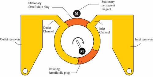
Pump design offers a number of advantages when compared to reciprocating positive displacement micropumps basically because pumping action takes place in the wafer’s plane and not perpendicular to it. This allows higher displacement and compression ratio without compromising power and voltage requirements of the driver. The design also provides a self-contained pumping chamber with no direct connection between the movement mechanism and the pumped fluid, which eliminates the possibility of external leakage.
Another important advantage of the FMM is that the shear stress levels in the flow field inside its channel are very small in almost the entire area of the channel, taking significant values only in the narrow strips near the walls (Kilani et al., Citation2011). Since the velocity profile across the pump’s channel takes a parabolic shape with almost zero velocity near no-slip boundaries, the contribution of the flow near the wall to the total flow out of the pump
is negligible, which means that the most of the flow out of the pump would be subject to negligible stresses. This is a favorable design features for stress-sensitive fluid pumping, where high stresses could damage the pumped fluid.
Valve-less operation is favorable especially when pumping particle-laden fluids as valves often cause blocking or clogging. Another useful design feature is that the pump doesn’t have stagnant regions or pockets within its flow field. If a fluid such as blood is being pumped, high shear and stagnant regions would lead to hemolysis and thrombogenesis and clotting (Aluri, Citation1999; Gregory et al., Citation2018; Jaouen et al., Citation1999; Wang & Fu, Citation2018) which would lead to the jamming of the rotating element or clogging of flow passages (Jang et al., Citation1999; Millward et al., Citation1994). Some investigators have proposed mesoscale and macroscale pump versions based on the same concept (Halhouli et al., Citation2010; Kilani & Abbadi, Citation2011; Kilani et al., Citation2016).
Reported testing results show that for a motor speed of 8 rpm a maximum flow rate of 45.8 μl/min was achieved with minimal imposed pressure. Attempting to increase the flow rate by increasing the motor speed or the channel cross sectional area would cause the immiscible fluid to lose integrity and mix with the pumped fluid.
A number of implementations based on the abovementioned design were presented by different investigators with different micfabrication methods and material, different actuation mechanisms and different values for and
(Fu et al., Citation2014; Gusenbauer et al., Citation2018; Al Halhouli et al., Citation2012; Liu et al., Citation2018; Michelson et al., Citation2019). Table summarizes the parameters for the six reviewed designs. Except for one of the designs presented in (Fu et al., Citation2014), the values
and
are 90° for all the designs shown in the table.
Table 1. Values of and
selected by different investigators
3. Analytical modeling
3.1. Flow model and boundary conditions
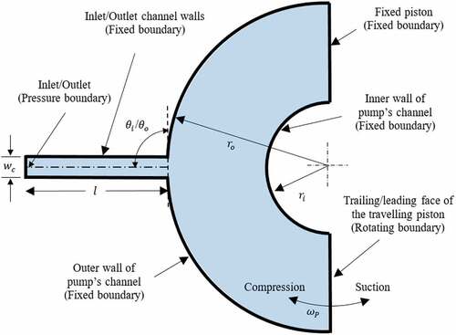
The flow field in the suction or the compression chamber of the pump can be modeled as a plug flow in a circular channel with rectangular cross section and with an inlet channel attached as seen in Figure . All the boundaries are fixed except those representing the trailing face of the moving piston and the pump’s inlet. The boundary representing the trailing face of the piston is modeled as a rotating boundary with a rotational speed equal to the piston’s angular speed , while that representing the inlet is modeled as a pressure boundary at the inlet/outlet pressure
. The angle
is the angle included between the centerline of the inlet channel and the tangent to the inner wall of the circular channel of the pump at the point where it intersects the centerline. We assume perfect contact between the walls of the pistons and the internal walls of the pump. The CFD model of Figure includes a relatively long channel. This helps eliminate the inaccuracies resulting from having the inlet or outlet angle very close to edges of the model. A similar model can be used for that for the compression chamber with the inlet channel replaced by the outlet channel, the trailing edge of the piston replaced by the leading edge, and the inlet angle replaced by the outlet angle.
Figure 2. Flow field in the suction/compression chamber.
We will restrict this analysis to low values of Reynolds number, . The flow under this assumption is laminar and inertia effects are negligible. For an incompressible Newtonian flow, the continuity and momentum equations are (White, Citation2009):
where is the velocity field and
is the pressure.
Using cylindrical coordinates and assuming laminar, fully developed, and unidirectional flow in the - direction (
) where
,
and
are the radial, vertical and transverse components of the velocity, EquationEq. (1)
(1)
(1) is automatically satisfied and the
- component of EquationEq. (2)
(2)
(2) becomes
The inertia and centrifugal forces for low are negligible compared to viscous force, and EquationEq. (3)
(3)
(3) becomes
3.2. Pressure field
By integrating EquationEq. (4)(4)
(4) the pressure in the suction, and the compression chambers, respectively, are found to be:
where and
are, respectively, the angles from the inlet port or outlet ports to the radial segment of interest in the suction or compression chamber. The pressure values at the trailing and the leading faces of the travelling piston,
and
, are readily obtained from EquationEq (5)
(5)
(5) and EquationEq. (6)
(6)
(6) as:
where and
are, respectively, the angular spans between the inlet and the trailing face of the piston, and between the leading face of the piston and the outlet. The difference in pressure between the leading and trailing faces of the piston is:
where is the difference between the externally imposed pressures at the pump’s inlet and outlet. The expression
is recognized to be the difference between the angular span between the inlet and outlet ports
and the piston angle
, which are design parameters that are independent of the location of the moving piston. EquationEquation (9)
(9)
(9) thus becomes:
EquationEquation (10)(10)
(10) shows that the pressure against which the piston moves is composed of two parts; the imposed pressure on the pump, or its head, and an additional component
resulting from viscous losses in the suction and the compression chambers
The above treatment did not consider the losses in the inlet and outlet channels connecting inlet or outlet ports of the pump to the inlet and outlet ports of the microfluidic device, or at sudden expansion or sudden contraction regions where the inlet or outlet channels join the pump’s channel. The pressure loss at the sudden expansion at the inlet, , and the sudden contraction at the outlet,
are defined in terms of inlet and outlet pressure loss coefficients
, and
as (Patiño-Jaramillo et al., Citation2022):
where is the piston’s mean radius. The parameters
and
were determined using CFD. The total pressure
against which the moving piston works is the sum of
, and the total losses in the suction path,
and in the compression path
where and
are given by:
The parameters and
in the above expressions are, respectively, the pressure losses in the inlet and outlet pipes, and
and
are viscous losses in the suction and compression chambers. The overall pressure loss between the pump inlet and the trailing face of the rotating piston is simply the sum of the individual pressure losses as the overall flow path can be treated a series connected network (Patiño-Jaramillo et al., Citation2022). The same argument is used for the overall pressure loss between pump outlet and the leading face of the rotating piston. The parameter
includes the overall losses in the suction side of the pump and include the losses effect of entry pipe length, sudden expansion at the inlet and viscous loss in the suction chamber, while the parameter
includes the effects of outlet pipe length, sudden contraction at the outlet and viscous loss in the compression chamber. Substituting the expressions in EquationEq. (15)
(15)
(15) and (Equation16
(16)
(16) ) into EquationEq. (14
(14)
(14) ), we obtain:
The effect of and
is absorbed in
and
since the other terms are independent of the angle.
3.3. Flow rate, torque, input power, output power and mechanical efficiency
Assuming incompressible and non-slip flow conditions, the theoretical flow rate into or out of the pump is found by integrating the velocity normal to the leading or trailing face of the travelling piston over its radial span, where the differential area
where
is the height of the piston:
Similarly, the theoretical torque that is required to rotate the travelling piston is found by integrating the product of the radial distance from the center of the pump and the force acting on the piston
over the radial span of the piston:
Recognizing as the width
of the piston, and
as its mean radius
, EquationEq. (18)
(18)
(18) and (Equation19
(19)
(19) ) become:
where is the area of the trailing or leading face of the piston. The input power
and the output power
are found using EquationEq. (21)
(21)
(21) and (Equation22
(22)
(22) ) to be:
Using EquationEq. (22)(22)
(22) and (Equation23
(23)
(23) ) along with EquationEq. (14)
(14)
(14) , (Equation15
(15)
(15) ) and (Equation16
(16)
(16) ), the mechanical efficiency
is:
which states that the mechanical efficiency is simply the ratio between the pump head and the pressure against which the travelling piston moves. Using EquationEq. (24)(24)
(24) along with EquationEq. (14)
(14)
(14) , (Equation15
(15)
(15) ) and (Equation16
(16)
(16) ), we obtain:
The expressions in EquationEq. (24)(24)
(24) and (Equation25
(25)
(25) ) give
when
. This is an expected result since the pressure loss in the suction and in the compression paths would be zero in either case. The expressions will also result in
when
or when
, which is also expected.
4. CFD simulations
CFD analysis was performed using ANSYS Fluent software, which uses Finite Volume Method (FVM) to solve the Navier-Stokes equations. The package allows the use of different discretization schemes to attain the suitable grid for simulating the flow field. The geometries, meshing and boundary conditions of the pump were created with ANSYS Workbench and exported to the preprocessor of the package. The 3D model domain for flow computations was carried out on 180° curved channel section. This 180° circular channel section represents half portion of the channel in order to reduce the computer resource requirements and improve the computational speed. The unstructured grid scheme with Tetrahedral elements was optimized to be appropriate for the present study. Inflation algorithm was used to generate thin cells adjacent to the boundaries of interest, thus, resolve viscous boundary layer in CFD.
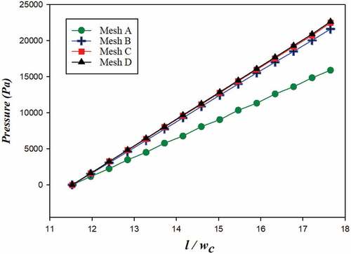
A mesh sensitivity analysis was performed to quantify the impact of mesh size on the results. Four meshes namely Mesh A, Mesh B, Mesh C, and Mesh D ranging from 2000 to 20,000 cells were generated and presented in Figure . The pressure results were analyzed along the centerline of the exit/inlet channels of the model and the differences in meshes were reflected in Figure . The result shows that the coarse Mesh A has the lower pressure result and the medium Mesh B has a significant increase in pressure. A noticeable difference between Mesh C and Mesh D (very fine mesh) indicates that refining the mesh further is not significant, hence, in Mesh C about 17,000 cells were adopted.
Figure 3. Comparison of mesh generated for (Mesh A) coarse, (Mesh B) medium, (Mesh C) fine, and (Mesh D) very fine.
Figure 4. Comparison of the numerical results for different mesh sizes.
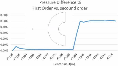
First-order and second-order momentum schemes results are compared as shown in Figure . The results show that along the straight channel section the difference is negligible, it increases inside the pump case, yet still its very difference is very small to about 0.5%.
Figure 5. Comparison of first order to second order momentum schemes.
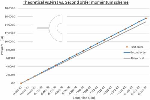
On the other hand, Figure compares the simulation results and the results obtained from the Hagen-Poiseuille formula for laminar flow pressure drop in straight channels, where
is the average speed of flow in the channel and
is its hydraulic diameter. The results shows that the first- and second-order schemes are in good agreement with the analytical results, which help in verifying the correctness of the obtained CFD results.
Figure 6. Comparison of the numerical results to analytical solution.
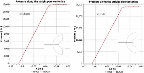
Both the Simple and coupled scheme were also tested to solve the pressure–velocity coupling equations, in which the convective terms were treated using the second-order upwind scheme and least square cell based gradient discretization. The pressure results were analyzed along the centerline of the channel. Both simple and coupled numerical schemes gave the same results upon convergence to residual as shown in Figure . Two velocities were tested 4 rad/s and 2.6 rad/s.
Figure 7. Comparison of the numerical results for different numerical schemes.
The geometric and physical quantities used in the computational domain are listed in Table . The boundary conditions were defined as velocity for the face representing the moving face of the piston and pressure at the face representing the channel inlet or outlet while all other faces were defined a stationary with no-slip conditions. The inlet and outlet angles considered were and
. The flow field was treated as steady, laminar, discounting the energy equation, and the solver was segregated. In addition, a second-order upwind scheme was used for the momentum equations while a second order pressure interpolation scheme was used for pressure. The scaled residual for the continuity and momentum equations was used to judge the convergence of the scaled over the unscaled equations. The solver iterated the equations until the scaled residuals were stabilized at a constant value to ensure convergence.
Table 2. Geometric and physical quantities used in the CFD model
5. Results and discussion
Figures show the CFD generated pressure contours in the suction and compression sides for the angles investigated. The presented solutions are for steady-state condition with rad/s (25 rpm). The contours are produced using
kPa, which eliminates the effect of imposed pressure on the calculated pressure values. Figure shows that the pressure at the suction side drops as flow progresses from the inlet toward the trailing face of the traveling piston. Conversely, Figure shows that the pressure in the compression side of the pump drops as the flow progresses from the leading face of the moving piston towards the outlet. Both of these drops are due to the viscous pressure losses associated with the flow. Figure also shows that
is minimum when
and increases with
where it takes its maximum value at
. Similarly, Figure shows that
is minimum when
and increases with
where it takes its maximum values when
.
Figure 8. CFD pressure contours in the suction chamber.
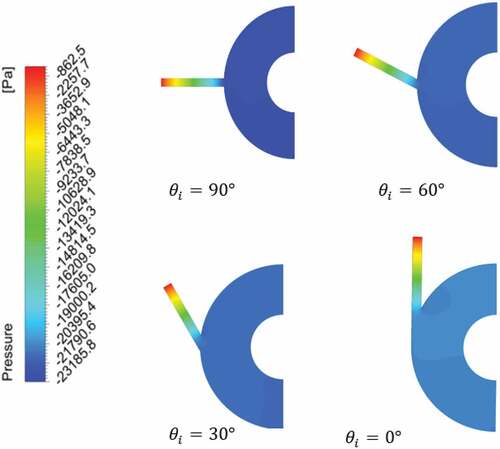
Figure 9. CFD pressure contours in the compression chamber.
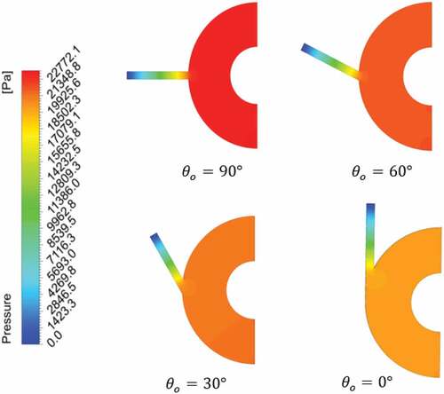
Table shows the values of ,
,
,
and
for the angles investigated. The values of
and
are calculated from EquationEq. (15)
(15)
(15) and (Equation16
(16)
(16) ) based on
Pa, which is calculated analytically using Hagen-Poiseuille formula for laminar flow pressure drop in straight channels. The values of
and
shown in the Table are calculated from EquationEq. (15)
(15)
(15) and (Equation16
(16)
(16) ) using values for
and
obtained from CFD simulation. The value of
is calculated by subtracting the pressure at a section 15° from the inlet toward the suction chamber from the pressure at the trailing edge of the moving piston which gives
Pa for all the cases considered. Also, the value of
, is calculated by subtracting the pressure at the leading edge of the trailing piston from the pressure at a section 15° from the outlet toward the compression chamber, which gives the
for all the cases considered. The consistent results obtained for or
and
are expected since the flow conditions don’t change inside the suction and compression chambers away from the inlet and outlet. This also ensures that the effect of the vortices generated the inlet and the outlet are eliminated.
Table 3. Inlet and outlet pressure loss coefficients for different values of inlet and outlet angles
It is observed that pressure losses in the inlet and outlet straight channels are much larger than the pressure loss of sudden expansion/compression
, /
, and the pressure loss
and
of the suction and compression chambers. This is expected as the inlet and outlet channels were intentionally created to be long to isolate the effect of model inlet from the pump’s inlet and outlet, which is the phenomena of concern in this study.
The listed values of and
for each angle are calculated from (12) and (13). The Table shows that
is consistently larger than
for the ranges of
and
considered. This can be explained by the high levels of swirling, vorticity and flow separation at the sudden expansion zone at the inlet, which are not present in a high level in the sudden contraction zone present at the outlet. This also explains the higher value for
compared to
in the CFD results
Table shows how ,
,
and
change with
and
. The listed values for
are based on a the given values of
and a nominally selected
. The Table shows that a 5% rise in
is achieved as
and
are changed from
to
for the pump considered. Figure shows the variation of
and
as a function of
and
.
Figure 10. Variation of and
with
and
.
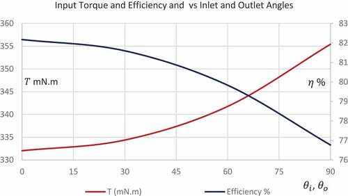
Table 4. Values of ,
,
and
for different values
and
The minimum value of takes place at
and its value increases by more than 5 folds when
. Similarly, The minimum value of
takes place at
, however
only doubles as
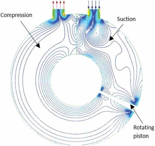
. The inlet angle has a much more pronounced effect on its respective pressure loss coefficient than that the outlet angle. This is because the swirling and vorticity losses at the inlet would be greatly reduced by a gentler inlet angle. Since these effects are not present in a high magnitude at the outlet, reducing the outlet angle will not produce the same effects. CFD results for the streamlines in the suction and compression chambers of the pump are shown in Figure , and they confirm the presence of higher levels of vorticities in the suction side than in the compression side.
Figure 11. Streamlines in the suction and compression chambers.
In addition to their effect on efficiency and power input, the results presented in Figure show that high values for and
would increase the resistive torque against the pistons and could result in limiting the usage of the pump to applications demanding high pump pressure head. The additional pressure from the increased pressure loss coefficient at the inlet and outlet causes the torque to increase and this may overcome the maximum torque provided by the mangetic coupling between the external driver magnets and the driven immiscible plug magnets.
6. Conclusions
FMM micropumps have been proposed by several investigators as they offer promising advantages in particle-laden and stress-sensitive pumping applications. A review of the available published designs shows that the values of and
were selected to be
in almost all of the published designs. The paper presented a CFD investigation of the effect those angles on pump performance. It is shown that a
value for
and
would significantly increase the pressure difference generated between the leading and the trailing faces of moving piston, and thus affect the torque, power and overall efficiency of the pump. A 5.4% rise in the mechanical efficiency is achieved by reducing
and
from
to
.
CFD investigation shows that a gentler contributes significantly to reducing the swirling, separation and vorticity losses at the sudden expansion region of the inlet with
at
dropping to 20% of its value at
. The effect of
on
is less pronounced, as
is only almost halved by reducing
from
to
. This is explained by that the swirling and vorticity effect are present to a much higher level at the sudden expansion of the inlet, than at the contraction at the outlet. Reducing the outlet angle will not therefore produce the same effects as that at the inlet. CFD results for the streamlines in the suction and compression chambers of the pump are shown in Figure , and they confirm the presence of higher levels of vorticities in the suction side than in the compression side.
The above findings take an emphasized signficance when considering that an increased piston differential pressure would limit pump’s usage in application demanding high pressure. One problem in magnetically driven synchronous pump occurs when the travelling piston is subject to high resistive torque such that the driving torque from the driving magnet is not enough to cause the piston to move, leading to slippage. This problem is exacerbated when higher values of results from sharper
and
. When an immiscible fluid plug is used as the piston, the higher differential pressure can also lead to increased magnetic fluid instability.
Disclosure statement
No potential conflict of interest was reported by the author(s).
Additional information
Funding
Notes on contributors
Sufian Shaker
The authors’ research work focuses on the development, analysis and optimization of microscale and macroscale double piston synchronous pumps (DPSP). A DPSP works by the synchronized rotation of two magnetic pistons inside a circular housing and offer a number of advantages compared the currently available micropump especially in particle-laden and stress-sensitive flow applications. The ferrofluidic magnetic micropump is one class of DPSM where the pistons are made of ferrofluidic plugs which are immiscible to the pumped fluid.
Besides CFD simulation and analysis, authors’ work on the subject includes the development of direct drive DPSPs. Direct drive DPSPs overcome the problem of magnetic slippage which takes place when external magnets are used as drivers for the pistons. Direct drive concepts based on servomotors, intermittent gearing and drag-link four bar mechanisms are currently investigated.
References
- Al Halhouli, A., Kilani, M., Waldschik, A., Phataralaoha, A., & B¨uttgenbach, S. (2012). “Development and testing of a synchronous micropump based on electroplated coils and microfabricated polymer,” magnets. Journal of Micromechanics and Microengineering, 22(6), 065,027. https://doi.org/10.1088/0960-1317/22/6/065027
- Alrifaiy, A., Lindahl, O. A., & Ramser, K. (2012). Polymer-based microfluidic devices for pharmacy, biology and tissue engineering. Polymers, 4(3), 1349–17. https://doi.org/10.3390/polym4031349
- Aluri, S. (1999). Hemolysis induced by mechanical heart valve closure. The University of Iowa.
- Archer, R. A., & Mandviwalla, X. 2007. CFD as a design tool for a conducting polymer micropump. Proc. of the 16th Australasian Fluid Mechanics Conference, 16AFMC pp. 803–806
- Ayala, M., & Cimbala, J. M., 2021. Numerical approach for prediction of turbulent flow resistance coefficient of 90° pipe bends. Proceedings of the Institution of Mechanical Engineers, Part E: Journal of Process Mechanical Engineering, 235(2), pp.351–360.
- Bußmann, A. B., Grünerbel, L. M., Durasiewicz, C. P., Thalhofer, T. A., Wille, A., & Richter, M. (2021). Microdosing for drug delivery application—A review. Sensors and Actuators, A: Physical, 330, 112820. https://doi.org/10.1016/j.sna.2021.112820
- Darabi, J., & Rhodes, C. 2005. CFD modeling of an ion-drag micropump. Sensors and Actuators, A: Physical, 127(1), 94–103. https://doi.org/10.1016/j.sna.2005.10.051
- Duan, B., Guo, T., Luo, M., & Luo, X., “A mechanical micropump for electronic cooling,” Fourteenth Intersociety Conference on Thermal and Thermomechanical Phenomena in Electronic Systems (ITherm), 2014, pp. 1038–1042. https://doi.org/10.1109/ITHERM.2014.6892395
- Felfoul, O., Becker, A., Bergeles, C., & Dupont, P. E. (2015). Achieving commutation control of an MRI-powered robot actuator. IEEE Transactions on Robotics, 31(2), 387–399. https://doi.org/10.1109/TRO.2015.2407795
- Fu, L.-M., Fang, W.-C., Hong, T.-F., & Lee, C.-Y. (2014). A magnetic micropump based on ferrofluidic actuation. International Journal of Automation and Smart Technology, 4(2), , 77–82. https://doi.org/10.5875/ausmt.v4i2.311
- Gareeva, R. G., Sypin, E. V., Lukjanov, M. V., Povemov, E. S., Kirpichnikov, A. N., & Leonov, G. V., 2003, July. Research of an opportunity of recognition of condition of the step motor jamming and slippage under the characteristics of controlling currents. In 2003 Siberian Russian Workshop on Electron Devices and Materials. Proceedings. 4th Annual (IEEE Cat. No. 03EX664) (pp. 236–241). IEEE.
- Gregory, S. D., Stevens, M. C., & Fraser, J. F., Ed. (2018). Mechanical circulatory and respiratory support. 301–334. https://www.elsevier.com/books/mechanical-circulatory-and-respiratory-support/gregory/978-0-12-810491-0
- Gusenbauer, M., Mazza, G., Posnicek, T., Brandl, M., & Schrefl, T. (2018). Magnetically actuated circular displacement micropump. The International Journal of Advanced Manufacturing Technology, 95(9–12), 3575–3588. https://doi.org/10.1007/s00170-017-1440-5
- Halhouli, A., Kilani, M., & Büttgenbach, S. (2010). Development of a novel electromagnetic pump for biomedical applications. Sensors and Actuators, A: Physical, 162, 172–176.
- Hassan, R., Cesmeci, S., Baniasadi, M., Palacio, A., & Robbins, A. (2022). A magnetorheological duckbill valve micropump for drug delivery applications. Micromachines, 13(5), 723. https://doi.org/10.3390/mi13050723
- Hatch, A., Kamholz, A. E., Holman, G., Yager, P., & Böhringer, K. F. (2001). A ferrofluidic magnetic micropump. Jmems, 10, 215–221. https://doi.org/10.1109/84.925748
- Jang, L., Morris, C. J., Sharma, N. R., Bardell, R., & Forster, F. Transport of particle-laden fluids through fixed-valve micropumps. ASME IMECE 1999. Micro-Electro-Mechanical Systems (MEMS) (pp. 503–509). Nov. 14–19, 1999. https://doi.org/10.1115/IMECE1999-0312
- Jaouen, P., Vandanjon, L., & Quéméneur, F. (1999, May). The shear stress of microalgal cell suspensions (Tetraselmis suecica) in tangential flow filtration systems: The role of pumps. Bioresource Technology, 68(2), 149–154. https://doi.org/10.1016/S0960-8524(98)00144-8
- Kilani, M., & Abbadi, A., “Method and apparatus for pumping a fluid using magnetic pistons,” GB2477276 British Patent, 03 August, 2011.
- Kilani, M., Halhouli, A. A., & Büttgenbach, S. (2011). Shear stress analysis in a ferrofluidic magnetic micropump. Journal of Nanoscale and Microscale Thermophysical Engineering, 15(1), 1–15. http://dx.doi.org/10.1080/15567265.2010.502923
- Kilani, M., Khasawneh, H., Badran, A., & Awidi, A. (2016). Further development on a gentle electromagnetic pump for fluids with stress-sensitive microparticles. Sensors and Actuators, A: Physical, 440-447, 247. http://dx.doi.org/10.1016/j.sna.2016.06.031
- Kovachev, N., Canals, A., & Escarpa, A. (2010). Fast and selective microfluidic chips for electrochemical antioxidant sensing in complex samples. Analytical Chemistry, 82(7), 2925–2931. https://doi.org/10.1021/ac9029218
- Laser, D. J., & Santiago, J. G. (2004). A review of micropumps. Journal of Micromechanics and Microengineering, 14(6), R35. https://doi.org/10.1088/0960-1317/14/6/R01
- Laser, D. J., & Santiago, J. G. (2004). A review of micropumps. Journal of Micromechanics and Microengineering, 14(6), R35. https://doi.org/10.1088/0960-1317/14/6/R01
- Liu, B., Zhen, Z., Yang, J., & Li, D. (2018). A rotary ferrofluidic vane micropump with C shape baffle. Sensors and Actuators, B: Chemical. https://doi.org/10.1016/j.snb.2018.02.113
- Ma, H. K., Luo, W. F., & Su, H. C., “Development of one-side actuating liquid cooling diaphragm micropump for a multimedia system,” 2011 International Conference on Multimedia Technology, 2011, pp. 6307–6310, https://doi.org/10.1109/ICMT.2011.6002096
- Michelson, T., Rudnick, J., Baxter, J., & Rashidi, R. (2019, November). A novel ferrofuid-based valve-less pump. IMECE, 7, 11–14. https://doi.org/10.1115/IMECE2019-10790
- Millward, H., Bellhouse, B., Nicholson, A. M., Beeton, S., Jenkins, N., & Knowles, C. J. (1994). Mammalian cell damage in a novel membrane bioreactor. Biotechnology and Bioengineering, 43(9), 899–906. https://doi.org/10.1002/bit.260430909
- Patiño-Jaramillo, G. A., Iglesias, I., & Vera, M. (2022). Laminar flow and pressure loss in planar tee joints: Pressure loss coefficients. European Journal of Mechanics-B/Fluids, 94, 263–275. https://doi.org/10.1016/j.euromechflu.2022.03.004
- Pramod, K., & Sen, A. K. (2014, June 5). Flow and heat transfer analysis of an electro-osmotic flow micropump for chip cooling. Journal of Electronic Packaging. Packag. September 2014; 136(3), 031012. https://doi.org/10.1115/1.4027657
- Shaker, S., Khan, A., & Kilani, M., “Effect of inlet angle and outlet angle on the performance of double-piston synchronous pumps” IEEE 2020 ASET Conferences. Dubai. UAE, pp. 1–4, 2020
- Takeuchi, K., Takama, N., Sharma, K., Paul, O., Ruther, P., Suga, T., & Kim, B. (2022). Microfluidic chip connected to porous microneedle array for continuous ISF sampling. Drug Delivery and Translational Research, 12(2), 435–443. https://doi.org/10.1007/s13346-021-01050-0
- Terjesen, B. F., Gorle, J., & Summerfelt, S. T. (2019). Hydrodynamics of Atlantic salmon culture tank: Effect of inlet nozzle angle on the velocity field. Computers and Electronics in Agriculture, 158:109–121. February 2019. https://doi.org/10.1016/j.compag.2019.01.049.
- Tsui, Y. Y., & Lu, S. L. (2008). Evaluation of the performance of a valveless micropump by CFD and lumped-system analyses. Sensors and Actuators, A: Physical, 148, 138–148. https://doi.org/10.1016/j.sna.2008.06.036
- Vante, A. B., & Kanish, T. C. (2022). Experimental investigation on digital offset switching strategy for precise dosing using digital multiple micropump infusion system. Microfluidics and Nanofluidics, 26(12), 1–19. https://doi.org/10.1007/s10404-022-02591-7
- Verma, A., & Bhattacharyya, S. (2021). Microfluidics-the state-of-the-art technology for pharmaceutical application. Advanced Pharmaceutical Bulletin, 12(4), 700–711. https://doi.org/10.34172/apb.2022.073
- Wang, Y. N., & Fu, L. M. (2018). Micropumps and biomedical applications–A review. Microelectronic Engineering, 195, 121–138. https://doi.org/10.1016/j.mee.2018.04.008
- White, F. M. (2009). Fluid mechanics (7th) ed. McGraw-Hill.
- Xianjin, X., Longhui, W., & Xiaojun, Y. (2016). Magnetic driving method of inspection robot for HVDC transmission lines. Journal of Zhejiang University (Engineering Science), 50(10), 1938–1944. http://www.zjujournals.com/eng/Y2016/V50/I10/1937