
 ?Mathematical formulae have been encoded as MathML and are displayed in this HTML version using MathJax in order to improve their display. Uncheck the box to turn MathJax off. This feature requires Javascript. Click on a formula to zoom.
Abstract
Production managers seek cost-effective methods to meet the basic requirements of a modern manufacturing system, as several conventional machine tools in most manufacturing industries face abandonment or require upgrades due to challenges related to precision and accuracy. This study presents an innovative mechatronic approach that combines three key machine tool parameters: speed, pressure and alignment modules. It integrates them into conventional machine tools as an integrity upgrading enabler through real-time monitoring. A dynamic programming model was used to obtain the integrity and a generated Python software named INTEGMAC, connected seamlessly with Integrity Evaluator 1.0 hardware to analyze real-time attributes of machine tools. INTEGMAC recommends remedial actions, where necessary, to enhance machine tool integrity and was successfully tested on a Boxford 11-30 Industrial Lathe, which improved the electric motor and spindle speeds, offset and angular misalignment, hydraulic and pneumatic pressure readings to meet the manufacturer’s benchmark specification. These collective modifications resulted in a significant increase in total integrity from 78.24% to 95.78%. Similar comparable results were obtained from follow-up tests to validate the performance of the developed system. This solution is currently applied in the machine tool industry and can also be extended to other industrial machines.
Reviewing Editor:
1. Introduction
Old and operational conventional machine tools in the form of lathes, drilling machines, milling machines, and the like have been in existence for a while for producing metal and wood machine components. The recent development in machine tools and integration into Industry 4.0 and beyond have replaced these old conventional machine tools with highly developed computer numerical control (CNC) machines. Nevertheless, these conventional machines are still in existence and operational but with less adaptation to modern machine tool functions. This has necessitated the drive to digitize production factories through machine tools and machining processes and make them intelligent to enhance their efficiency, precision and technological versatility while ensuring efficient systemic servicing (Jedrzejewski and Kwasny, Citation2017).
Traditional retrofitting methods for replacing motion and control systems have been employed to improve their performance. Smart retrofitting concepts have also been applied by adding smart sensors to monitor real-time machine parameters such as temperature, load and vibration (Al-Maeeni et al., Citation2020). However, other cogent machine parameters, such as machine tool speed monitoring, machine alignment and the hydraulic and pneumatic components influencing the integrity of conventional machine tools, such as the Lathe machine, have not yet been fully explored. Furthermore, the upgrade of conventional machine tools using a mechatronic approach comprising an integrated system of sensors, data processing tools and machine integrity analysis software has not been sufficiently highlighted by existing works in the literature. Therefore, this study aims to upgrade conventional machine tools by using specific machine parameters such as the electric motor and spindle speed, the hydraulic and pneumatic pressure and the alignment of machine tools to improve their performance and versatility through a mechatronics approach.
Mechatronics, which is one of the recent interdisciplinary areas of engineering with improved intelligence and speedy sensing, actuation and decision-making, was selected for the upgrade. Mechatronics systems design involves the integration of mechanical, electrical and software engineering (Zheng et al., Citation2016). It has been defined as the coordinated integration of mechanical engineering with electronics and intelligent computer control in the design and manufacture of products and processes (Bolton, Citation2015). It has also been integrated into some specific sections of machine tools to improve productivity. Areas such as precision positioning and error compensation have been improved by mechatronics by providing solutions in the main and feed drives, frame components and guide systems (Neugebauer et al., Citation2007). Other areas, such as reduction in vibration and geometric areas, have also been assisted with the aid of mechanical and mechatronic systems through multiple-tuned mass dampers, ultrasonic measuring devices and mechanical compensation units (Pelayo et al., Citation2023). The accuracy of outdated machine tools has also been improved by using microsystem technology to enhance modular machine tool frames and internally cooled cutting frames (Uhlmann, Lang, et al., Citation2017).
Mechatronics has been used to improve and enhance industrial machines’ functional accuracy, flexibility and operability (Zhao, Citation2020). Such illustrations involve the usage of a tool wear prediction upgrade kit as an add-on to a conventional machine tool using an industrial-grade edge device with neural networks to monitor machine processes and increase prediction accuracy (Jiang et al., Citation2022). Other works in the literature proposed a system architecture to upgrade conventional machine tools using external sensors for collecting data and storing it on cloud databases for machine analysis and monitoring (Keshav Kolla et al., Citation2022). This architecture was used to develop a cloud-based monitoring system to process unsupervised machine data for speed control, motor load uncoupling and misalignment prevention (Dias et al., Citation2021). However, further mechatronic system development is still needed to enhance machine tool operation in terms of directly processing data on the edge and monitoring the integrity in real time to avoid latency and throughput issues related to cloud processing.
Furthermore, the main belt drives of most conventional machines were upgraded to electric drives built into the spindle using mechatronic means (Goman, Citation2020). The spindle is one of the most critical subsystems of a machine tool, as it determines the quality of the workpiece in terms of the removal rate (Baur et al., Citation2020). Different rotating spindle speeds of micro-milling machines have been adjudged to predict chatter vibrations that cause tool wear and poor surface quality, thereby determining frequency response functions (Pelayo et al., Citation2023). This tool wear was detected through the monitoring of electric power in conjunction with a mechanistic model (Goodall et al., Citation2020). The spindle angular thermal errors of machine tools, affected by spindle rotation speed, position and environmental temperature variations across seasons, not only degrade dimension accuracy but also impact the shape accuracy of machined parts (Peng et al., Citation2023). However, other parameters, such as the actual spindle speed, were never compared to the expected spindle speed to confirm the accuracy level of the spindle. Some works in the literature also considered adding a spindle speed increaser to upgrade outdated milling machines (Uhlmann, Thom, et al., Citation2017), but other cogent parameters, such as the hydraulic and pneumatic modules in the form of cooling and lubrication during the upgrade, were not considered.
The cooling and lubrication system aids machine tools in attaining the necessary precision and stability levels, and it also helps maintain thermal stability (Feng and Huang, Citation2020). The hydraulic system, recognized as one of the most error-prone subsystems, requires improved monitoring and error prediction capabilities to anticipate potential failures (Baur et al., Citation2020). The coolant used in hydraulics eases the cutting tool to perform accurate machining of workpieces (Bleicher et al., Citation2023). Insufficient lubrication and cooling of guide chamfers and cutting tool edges lead to accelerated tool wear (Oezkaya et al., Citation2022). Hence, the hydraulic and pneumatic components of the upgraded machine tools need to be fully functional to propel the efficiency of the cooling and lubrication system. This aspect was partly achieved by a previous study carried out when the spindle dimensions of the optimum cooling channel were redesigned and simulated, and this raised the spindle cooling efficiency, thereby enhancing the machine tool’s precision and accuracy (Li et al., Citation2020). Nevertheless, the actual pressure of lubricant reaching the spindle and other critical areas of the machine tools was not considered. Additionally, an automated lubrication system was developed to assist machine tool guideways in achieving higher precision and less oil consumption through sensitive temperature signals obtained from temperature sensors (Sparham et al., Citation2014). The minimum quantity cooling lubrication technique was found to be better than traditional cooling methods, as it tends to optimize the use of coolants with excellent temperature reduction effects (García-Martínez et al., Citation2019). Likewise, both hydraulic fluid pressure and pneumatic pressurized air are needed during the minimum quantity cooling lubrication technique for proper delivery to the cutting area (Ashmawy et al., Citation2023; Patole and Kulkarni, Citation2017). This was the case when high-pressure coolant improved the machining of titanium and its alloys, as its cooling effect improved the tool wear and life together with the surface roughness of the material (Pimenov et al., Citation2021). These actual pressures are not always measured and monitored with the expected pressures, as there are no installed sensors or monitoring equipment to confirm such pressures in conventional machines, thereby diminishing the expected accuracy from the machine tool caused by surface roughness errors.
Moreover, legacy machines were also incorporated by using Internet of Things devices through the ZigBee wireless mesh network to make the machines smart (Cunha et al., Citation2021). Augmented reality technique through Microsoft Holo Lens; an untethered reality headset was employed to visualize machine parameters such as vibration, temperature and loads to ensure machine maintenance is convenient for Industry 4.0 (Al-Maeeni et al., Citation2020). Deep learning techniques were also used to assess the degradation of industrial machines by monitoring vibration and classifying faults with higher accuracy (Li et al., Citation2019). Other works in the literature also considered a computer numerical control open architecture machine tool platform to implement technologies that aided easy hardware and software integration to improve electro-discharge machining (Zhao et al., Citation2020). This aided the introduction of Internet of Things-based sensors such as motion and proximity sensors, motion, vibration and temperature sensors in conjunction with Internet protocol cameras to be added to digitalize existing conventional machine tools and conform to Industry 4.0 (Sutopo et al., Citation2020). However, areas of improvement of other parameters were hugely ignored, as the authors only focused on bringing the machines online.
Additionally, tool condition monitoring was implemented using a universal wireless tool-embedded sensor node, and several reviews using artificial neural networks and dimension reduction techniques were used (Mohamed et al., Citation2022). Dimensionality reduction techniques were also proposed to monitor machine status in real-time for machines without prior data on degradation and failure (López de Calle et al., Citation2019). Higher machine tool precision and performance with improved dimensional accuracy have also been achieved through an upgrade from conventional to Mini CNC machines by strengthening the aluminum structure and replacing the traditional ball screw with a high-precision linear motor system, thus increasing surface quality (Jeerapongudom et al., Citation2022).
Conventional machine tools in most industries are abandoned because of varying challenges related to precision, accuracy, misalignment, etc., which are the basic requirements of modern manufacturing systems. The accuracy challenge of machine tools from the previous study was improved upon by evaluating tolerance performance indexes based on roundness, angularity and concentricity (Wu et al., Citation2020). The accuracy degradation can be greatly affected by misalignment and deformations that arise during the assembly process, thereby causing geometric machine tool inaccuracies (Budak et al., Citation2022). The misalignment challenge in machine tools was evaluated for classification and severity measurement for error prediction (de Sá Só Martins et al., Citation2021). Many previous studies were oblivious to addressing these challenges by developing a novel strategy for upgrading these conventional machine tools. The process of determining the degradation of both the structural and operational factors of machine tools was also elusive. This made it more difficult to diagnose and continuously upgrade old machine tools with minimal disruptions to production and to establish product quality levels attainable on machine tools. The quality of machine tools affects the quality of the manufactured parts (Wan et al., Citation2017). Thus, other critical machine parameters that improved conventional machine tool performance, such as the electric motor and spindle speed, hydraulic and pneumatic pressures and alignment, were not considered. There is now an urgent need to find the right means and methodology to generate machine tool information through upgrades to generate optimum machining conditions, thereby creating quantitative assessment and continuous monitoring of machine tool integrity. This study hereby contributes both theoretically and empirically to existing works of literature on machine tool upgrades through the development of a mechatronic decision tool for upgrading the versatility and operational performance of machine tools and a practical procedural approach to implementing the upgrade of conventional machines. Additionally, a framework for evaluating the overall integrity of machine tools was developed together with the establishment of baseline information for the effective operational performance of machine tools.
This research hereby explored the mechatronic system for easier machine upgrades by generating a mathematical model for calculating the integrity of machine tools and using the model to develop mechatronic software to obtain real-time machine information. It therefore recommends remedial decisions for machine tool improvement. The mechatronic system employed in this study comprises an integrated system of sensors, a data processing device, and machine integrity analysis software coupled to the conventional machine tool. The novelty of this research lies in the integrative monitoring and quantifying feature of the developed mechatronic system in addition to its decision-making process of recommending remedial actions to improve machine tool integrity, thereby upgrading the versatility of machine tools.
2. Materials and methods
This section describes the method used to carry out the research together with the materials used in developing the mechatronic system. This was achieved by developing a mathematical model to calculate the integrity using dynamic programming and a mixed linear programming approach. This model was used to develop an algorithm and flowchart for mechatronic software development. Recommended remedial actions were also integrated into the developed software to precisely select areas of improvement and recommend likely improvement techniques as obtained from intensive expert opinions and studies. The developed software was also integrated with developed mechatronic hardware to determine the integrity of the machine tool, as this was used to indicate the possible areas of improvement in the machine tool.
2.1. Mathematical formulation of machine tool integrity parameters
The model was formulated using critical integrity elements as input data to the model. The model was structured through three different modes: the mathematical formulation, the algorithm/flowchart mode and the software coding mode. These are further described in the subsections.
2.1.1. Elemental integrity calculation
Suppose a parameter measures Pan and its acceptable benchmark is Ps. Its Integrity, IN, is shown in EquationEquation (1)(1)
(1) . Integrity as defined in this study is the ability of a machine tool to perform to its initial manufacturer’s specification based on precision and accuracy, repeatability and high-quality surface finish.
(1)
(1)
If Pan is greater than Ps, the integrity automatically becomes IN = 1.
2.1.2. Total integrity calculation
Let the total integrity of a machine tool be IT and let there be N parameters for measurement and M of those parameters be in the category of death-knell. Death-knell parameters are parameters that completely demobilize the total integrity of a machine tool whenever it stops working, while pseudo-death-knell parameters, also known as temporary death, can be revived through partial replacement, overhaul or repair, thereby improving the integrity of the machine. Therefore, N-M will be included in the pseudo-death-knell/living characterization. The total machine tool integrity, IT, is as shown in EquationEquation (2)(2)
(2) .
(2)
(2)
Additionally, by adopting the mixed integer linear programming method to determine the values for death-knell parameters (for M1 and M2), its value either becomes zero (0) or (1) and at a minimum of 50% benchmark. This would be achieved by EquationEquations (3)–(6):
(3)
(3)
Subject to:
(4)
(4)
(5)
(5)
Otherwise,
(6)
(6)
where L1 is the integrity of the electric motor speed, L2 is the integrity of the spindle speed, L3 is the integrity of headstock alignment, L4 is the integrity of tool post alignment, L5 is the integrity of tailstock alignment, L6 is the integrity of hydraulic pressure, L7 is the integrity of pneumatic pressure, M1 is the integrity of crack and faults on guideways (death-knell parameters), M2 is the integrity of leadscrew, and n is the number of test runs. The integrity of these parameters is measured in %.
This mathematical formulation depicts that initially, during the machine integrity calculation, the death-knell parameters are assumed to be 1. Conversely, if after obtaining the pseudo-death-knell/living parameters to calculate the total machine integrity and after carrying out remedial actions in several trial runs, the total IT remains <50%, then either and/or the death-knell parameters become (0).
2.2. System algorithm and flowchart of the model
The steps and details of the algorithm are enumerated below.
2.2.1. Steps of the algorithm
C System Initiation
Step 1: Initiate software
Step 2: Select the machine tool to obtain its integrity
Step 3: Select the death-knell parameter tab under the genetics of characterization page
C Data Input
Step 4: Data input into death-knell parameters through the ‘get input from sensors’ tab
C Data Output
Step 5: Compute integrity to obtain integrity for death-knell pa parameters as output
Step 6: Initiate pseudo-death-knell/living parameters
C Data Input
Step 7: Data input into pseudo-death-knell/living parameters through the ‘get input from sensors’ tab
C Data Output
Step 8: Compute integrity to obtain integrity for pseudo-death-knell/living parameters as output
Step 9: Compute the total integrity and improve the integrity if applied cable
C Integrity Improvement
Step 10: Display remedial actions that can be carried out to improve integrity
Step 11: Recalculate integrity until full optimization
C System Stopping Rule
Step 12: Display total machine integrity after full improvement
2.2.2. Details of the algorithm
Sensor fusion algorithm was used in INTEGMAC software as integrated data from the speed, pressure and alignment sensors provided a comprehensive view of the upgraded machine tool. A recursive sensor fusion algorithm, the Kalman filter, was adopted to estimate the state of dynamic systems based on sensor measurements. It combines predictions from a dynamic model with sensor measurements to produce optimal estimates of the system’s state (Lindfield et al., Citation2019). This indicates the true state of the machine tool based on noisy sensor measurements thereby improving the accuracy and reliability of the data used for decision-making in INTEGMAC. The sensor fusion algorithm extracts meaningful features from sensor data, offering valuable insights into the machining process to identify deviations from the integrity of the machine tool. Utilizing this information, it recommends remedial actions to optimize machining performance thereby enhancing the integrity of the upgraded machine tool. Further details include:
System initialization: the system is initialized by selecting the specific machine tool to carry out its integrity.
Decision rules for calculating integrity: the death-knell parameter must first be calculated before calculating the pseudo-death-knell/living parameters. This is because if any of the death-knell parameters have zero elemental integrity, then the total machine integrity is zero.
System data input: the input parameters in the algorithm are the death-knell parameters, which are cracks and faults on guideways and leadscrews. Additionally, the input parameters for the Pseudo-Death-knell/Living Parameters are the electric motor speed, spindle speed, headstock alignment, toolpost alignment, tailstock alignment and hydraulic and pneumatic pressures. These input parameters were identified as critical integrity elements used in this study.
System data output: the elemental and total integrities are processed and sent as output.
System upgrade: integrity improvement can be initiated from the optimization tab to improve integrity, as the algorithm automatically selects the lowest elemental integrity and recommends remedial actions to be carried out by the machine operator/maintenance personnel, as indicated in . This is in support of the recommender system developed to select optimal process parameters for quality assessment and control from previous works (Babalola et al., Citation2023).
Figure 1b. Integmac User Interface Snapshots of Remedial Actions. (c) Integmac Snapshot of Computed Integrity.
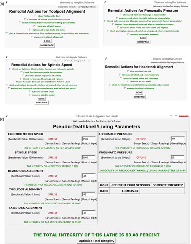
The criteria for selection were developed by selecting the lowest elemental integrity from all the calculated elemental integrities and recommending different remedial actions to be carried out. The remedial actions were programmed in the developed software to improve its integrity. These remedial actions were obtained from the maintenance logs of the different workshops visited during the assessment.
vi.Stopping rule
The system is fully complete and fully optimized when the total machine integrity is 100%, and there is no chance for more improvement by disabling the optimization tab.
2.2.3. Flowchart of the model
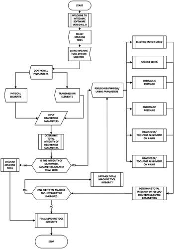
The flowchart of the model is displayed in . It integrates the algorithm and the mathematical formulation already discussed, whereby integrity parameters are measured by the attached component sensors and analyzed using the developed model to calculate the final total machine tool integrity. There is also a decision option in the flowchart that decides after calculating the total integrity to discard the machine tool if the integrity is zero. Otherwise, it provides an option to improve its integrity by selecting the element with the lowest integrity, recommending remedial actions to the machine operator, and recalculating integrity after the actions have been implemented, as shown in Figures 1(b) and 1(c). If the integrity cannot be further improved, then the flowchart determines the final total integrity of the machine tool and stops.
Figure 1a. Flowchart of the Model of the Mechatronic System.
2.3. Software development
A mechatronic software named InteGMac was developed for this research using the Python programming language. InteGMac was developed using the mathematical formulation together with the algorithm/flowchart discussed above. Python was chosen because it is an object-oriented language that is easy to read and understand. Python also enables rapid prototyping and reduces development time through its numerous free library packages. It connects and communicates easily with the Arduino Mega 2560 microcontroller used for this study to obtain signals and process them with speed. It is also a new-generation language that easily performs complex data analysis.
2.4. Identification of mechatronic system components
In developing a mechatronic system for data collection and processing procedures based on the model developed, a simple structure for the mechatronic system was designed, as shown in . The components of the mechatronic system include the following:
Figure 2. Structure of the Mechatronic System.
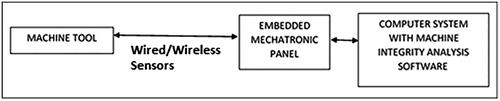
Machine Tool: the machine tool used for this research is a lathe machine. The conventional lathe is the basic machine workshop tool that is used for turning, facing, grooving and drilling and has boring metal materials attached to it. Although the lathe machine was used as a case study, this mechatronic system could also be applied to other machine tools. A comparison between the lathe machines and other machine tools has similar critical components as the lathe machine, as shown in .
Wired/Wireless Sensors/Lasers and Probes: these are the mechatronic components that are attached to the machine tool from the mechatronic panel. These elements are made to obtain signals from the machine tool, which is fed into the controller panel for analysis.
Embedded Mechatronic Microcontroller. The microcontroller panel used for this research was manufactured by Arduino. Arduino has been chosen due to its low cost, easily obtainable components and input/output processing capabilities. Arduino Mega 2560 was the exact model used, as it possessed an ATmega328 with a processing frequency of 16 MHz and 54 digital inputs/outputs together with an additional 16 analogue input/output pins most suitable for the study. This was chosen due to its low cost over existing works in the literature that used a Raspberry Pi 4, as it is also used to control and make the system a smart mechatronic panel (Keshava and Sree Rajendra, Citation2021).
The Arduino Software: Arduino codes were developed for this research using Arduino sketch programming language. The Arduino sketch drives the mechatronic system to obtain input signals from the connected sensors and transducers and sends them to the Arduino microcontroller. The microcontroller processes these signals and sends the values to the developed InteGMac software for determination of the integrity of the machine tool according to the developed model using easily integrated hardware-software mechatronic configurations.
Machine Integrity Analysis Software: this was developed using the Python programming language and named Integmac to analyze input sensor signals obtained from the connected sensor and process the signals using the developed mathematical model with the developed algorithm and flowchart. It then outputs the integrity of the machine tool numerically and recommends remedial actions to improve the integrity of the machine tool.
Table 1. Comparison between machine tools.
2.5. Development of the mechatronic system
The developed model from Section 2.1 determined both the structural and operational integrity of a machine tool and this was further integrated into the mechatronic system. InteGMac picks up data from sensors and transducers connected to the mechatronic system for integrity analysis and possible diagnostics, thereby improving the overall integrity in the long run. This method is an upgrade to earlier literature on starter sensor kit solutions that provided a cost-effective solution for obtaining machine data using mounted sensors on machines to monitor machine status (Alqoud et al., Citation2022). The main condition for this system is that the machine tool is expected to be operational, as this research focuses more on obtaining and improving the integrity and upgrading the versatility of the machine tool to an improved operational condition.
2.5.1. Measurement of integrity parameters
The major possible locations of probes/sensors for the determination of integrity on a lathe include the headstock, tailstock, bed, tool post/carriage, hydraulic/pneumatic elements and the electric control system. The tailstock in conjunction with the headstock was useful for the determination of machine alignment (G24), which, if properly aligned, will guarantee parallelism (G22) of machined products. shows the various probe locations, the possible measurement parameters and the actual parameters measured together with their applied sensors.
Table 2. Probe locations and measurement.
The sensor used to monitor the speed parameters was an infrared speed digital sensor with an LM393 comparator detection circuit and an onboard potentiometer. The hydraulic pressure transducers used were a 2.4 MPa, 5 V DC with a working temperature range between 0° and 85° and a working current of 10 mA. The pneumatic pressure transducer used was an IP67, 500 psi maximum reading capacity with a linear voltage output of 0.5–4.5 V and a working temperature of −40 to 120 °C. These sensors connect easily and seamlessly with an Arduino mega 2560 ATMEGA microcontroller through input/output (I/O) pins to process the input parameters.
A light-dependent resistor (LDR) alignment grid was developed to measure machine tool offset and angular misalignment. The grid works on the voltage divider rule principle and is composed of a grid of carefully arranged units of 80 LDR model 5537 with a rated power of 100 mW whose resistance changes depending on the light intensity on its surface. The grid’s center point consisted of a non-modulated laser receiving module that sends a high output whenever it receives a laser signal. It is arranged in rows and columns, of which it has nine even rows and nine even columns as shown in . The circuit was connected to five units of a 16-channel multiplexer that helped transform into 16 analogue inputs from five digital inputs and a single analogue input on the Arduino microcontroller. The CD74HC4067 high-speed CMOS 16-channel analogue multiplexer was used to extend the number of analogue pins available on the Arduino mega to the needed 81 units of LDRs for the research. The typical circuit diagram for a single LDR unit on this device is shown in .
Figure 3(a). LDR Circuit Diagram, (b) Direct connection of LDR to the Arduino Board, (c) LDR Grid with a multiplexer and Jumper cables.
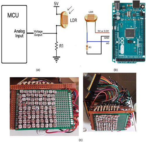
The voltage that appears at the analog input varies depending on the amount of light hitting the LDR. The LDR is connected to a 5 V power source and properly grounded. The LDR appears as a variable resistor in . The circuit uses a 1 kΩ pull-down resistor (R1) to restrict the current entering.
The LDR alignment grid worked alongside a Keyes KY-008 laser transmitting module operating within 5 V and with a wavelength of 650 nm and an output power of 30 mA. This laser transmitter was operated using an Arduino Nano and mounted on the headstock of a lathe using a well-machined cylindrical enclosure, as shown in . The Arduino nano was seamlessly connected with a three-axis MPU 6050 analogue gyro sensor/accelerometer through the I2C bus protocol to monitor the machine tool misalignment together, as shown in . However, in this study, machine tool integrity estimation was centered only on the speed, pressure and alignment module. This was in support of a previous study that used the screening process to obtain an optimal number of sensors to evaluate the accuracy level of machine tools in terms of thermal compensation (Tsai et al., Citation2020).
Figure 4. The alignment module is mounted onto the headstock, and the laser beam points towards the tailings stock.
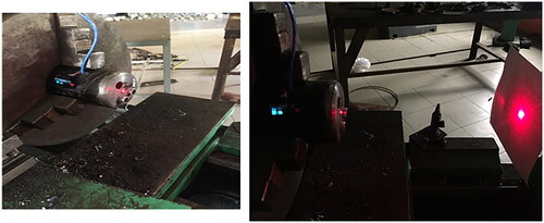
Figure 5. Mechatronic Circuitry.
It is presumed that attached sensors are capable of returning measured parameters with accuracy ranging within the limit set by the manufacturer of the measuring instrument. This is also sustainable for machine tools within the same range. The benchmark values for all the considered parameters of interest are also indicated according to the selected machine tools, as shown in . shows the alignment system mounted onto the headstock and the laser beam pointing on the tailstock.
2.6. Software development of the mechatronic system
The mechatronic system software was developed using the Arduino Sketch freeware program. The software was developed by first coding each of the elemental sensors and transducers and then integrating all the codes into a single sketch. Python programming was also developed to analyze the integrity values and recommend remedial actions.
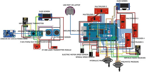
2.7. Development of mechatronic circuitry
To further achieve a developed mechatronic system for data collection and processing procedures based on the model developed, the mechatronic hardware also needs to be assembled according to a workable circuit diagram, as shown in , and linked with the already developed software that drives the entire mechatronic system.
2.7.1. Design configuration
The hardware was segmented into the speed module, the pressure module and the alignment module, in which the modules were distinguished by adaptation, adoption, reworking and/or modification of existing methods to suit the research purpose. Furthermore, the justification for selecting the mechatronic circuit elements was discussed, which precedes the assembly of all the circuit elements according to the already designed circuit diagram, as shown in for the mechatronic system. Some of the mechatronic system components, such as the LDR grid, were built in-house, while other components were bought out and assembled in an enclosure box mounted on the lathe for integrity analysis.
The mechatronic circuitry was designed using freeware software known as Fritzing. The mechatronic circuitry is divided into three separate modules to simplify its design:
Speed Module: this module measures the speed readings in revolutions per minute (rpm) using the infrared speed sensor attached to the machine lathe.
Pressure Module: this module measured both the hydraulic and pneumatic pressures in the machine tool. this module measured the pressures in Bars and Psi as obtained from the pressure transducers into the Integmac software.
Alignment Module: this module quickly and precisely evaluated the alignment of both the headstock to the tailstock, the headstock to the bed and the tailstock to the bed. The information obtained from this module was used to realign the machine tool by applying remedial actions for future production runs. This alignment module was adopted from Pinpoint Laser Systems and Hamar Laser Systems and was modified to suit the research purpose. The standard formula used for the total misalignment is as indicated in EquationEquations (8)
(8)
Figure 6. Mechatronic System Architecture.
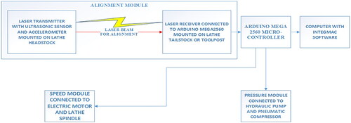
Figure 7. Schematic Sketch of Mechatronic System mounted on Lathe.
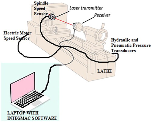
2.7.2. Assembly of components and mounting of circuitry on a lathe
The mechatronic system was assembled by strictly following the circuit diagram obtained from the Fritzing software. The components were carefully and tightly connected to the Arduino Mega 2560 using simple hand tools such as screwdrivers. A schematic sketch of the mechatronic system as mounted on Lathe is shown in . Some parts of the developed LDR circuit were soldered together to ensure tightness. shows the developed integrity evaluator.
Figure 8. Developed Integrity Evaluator.
2.8. Performance evaluation of the developed system
The calibration of applied sensors in various test modules was established using standardized benchmarks. The benchmark instrument used for calibration is the Standard DT-6234B digital tachometer, which was used to calibrate the speed sensor by ensuring that the output from both the speed sensor and the digital tachometer connected to the spindle was reading the same thing. The same process was also used to calibrate the pressure sensor using a WIKA Bourdon Gage and the developed alignment grid using a Mitutoyo dial indicator.
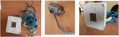
2.9. Integrity Evaluator 1.0 test on a Boxford 11-30 Industrial Lathe machine at Besade Engineering Works
The developed Integrity Evaluator 1.0 was also mounted on a Boxford 11-30 Industrial Lathe located at Besade Engineering Works Workshop, Ondo Town, Ondo State, Nigeria. The lathe was manufactured in 1989 and installed in the workshop in 1998. It has a 0.75 hp (0.55 kW) producing 9 speeds from 27 to 1490 revolutions per minute. It also has a well-supported spindle, together with splash-lubricated, hardened and ground headstock gears, ensuring that the lathe makes little noise. Electrical controls are located around the headstock’s front face together with an emergency stop button. Its internals run in an oil bath, and the apron controls with a micrometer dial push/pull button and lift/lower lever for selecting and engaging power feeds and direction.
Three cylindrical test workpieces of basic sizes of 35 mm, 60 mm and 90 mm were turned on the lathe to assess the machining accuracy and precision. Machining accuracy was assessed using tolerance grade levels and compared with the international standard tolerance grade ISO 286. The surface quality of the machined workpiece was measured in micrometers using the Mitutoyo surface roughness tester (Surftest SJ-201) with a maximum measuring length of 350 µm. The measurement of the surface roughness of the workpiece was conducted because it is a critical factor that determines the product quality in cutting operations such as water jet cutting, turning, milling and drilling among others (Abdullah et al., Citation2016). The higher the surface roughness, the lower the product quality and vice versa (Ilari et al., Citation2021).
3. Results
3.1. Calibration and testing of developed mechatronic system components
The results obtained from the calibration and testing of the developed mechatronic system components are shown in . The results established that the sensors used were found suitable within acceptable limits using the 3-σ criterion.
Table 3. Results of component calibration.
3.2. Results of test runs on the Boxford 11-30 Industrial Lathe
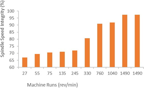
3.2.1. Spindle speed integrity
The results of spindle integrity are presented in . It was observed that there was a wide deviation of the infrared speed sensor readings mounted on the spindle compared to the benchmark speed operated on the Boxford 11-30 Industrial lathe machine between the first and last trial runs. This was a result of the aged machine, which was not made operational for a very long time. The lathe had speeds ranging from 27 rpm to 1490 rpm. Thereafter, remedial actions, such as replacing damaged transmission elements like belts and gears, and checking spindle bearing lubrication and voltage/current supply, as recommended by the mechatronic system using a large amount of expert experience and structured maintenance data, were intensively carried out to improve the spindle speed integrity from 67% to 97.3%. Previous research findings using smart retrofitting techniques on drill press by an electronic spindle descend meter assisted in the monitoring and control of critical process parameters such as speed (Ilari et al. Citation2021; Guan et al., Citation2023) also corroborated our result findings to be similar. This also validated the research findings of monitoring process parameters in real-time and for further analysis.
Figure 9. Spindle Speed Integrity Chart.
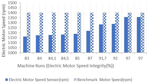
3.2.2. Electric motor speed integrity
The results of the electric motor speed integrity are presented in . It was observed that the electric motor speed reading at 1162 rpm in the first run was very low compared to the manufacturer specification of 1400 rpm used as a benchmark. This was improved to 1358 rpm after several trial runs by the developed INTEGMAC software by recommending remedial actions carried out on the machine, such as checking motor bearing lubrication, checking and replacing damaged switches, voltage/current supply checking, earth wiring and other circuit elements to be implemented by the machine operator. This was found to improve the integrity from 83% to 97%. The power rating of the electric motor was also found to have a strong relationship with the electric motor speed. This decision-making process also tallied with previous research on hybrid intelligent decision-making processes during manufacturing to improve the machining process, as the overall corrected accuracy significantly improved (Guan et al., Citation2023).
Figure 10. Electric Motor Speed Integrity Chart.
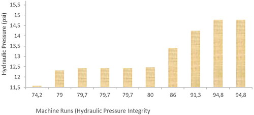
3.2.3. Hydraulic pressure integrity
The results of hydraulic pressure integrity are presented in . It was observed that the initial hydraulic pressure reading at 11.57 psi compared to the manufacturer specification of 15.6 psi used as the benchmark was far below the benchmark. The developed software recommended remedial actions to be carried out on the lathe, such as checking for leakages and blockages in the hydraulic pump by the operator/maintenance personnel to improve its integrity. This was implemented by the machine operators, and this effectively improved it from 74.2% to 94.8% after several machine runs.
Figure 11. Hydraulic pressure integrity chart.
3.2.4. Pneumatic pressure integrity
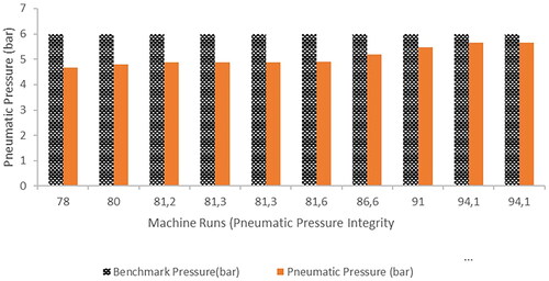
The results of the pneumatic pressure integrity are presented in . It was observed that the initial pneumatic pressure reading at 4.68 bar, compared to the manufacturer specification of 6 bar used as the benchmark, was far below the acceptable benchmark reading. This was improved by the developed software by recommending remedial actions carried out on the lathe, such as checking for leakages and blockages in the accumulators by the operator/maintenance personnel to improve the integrity from 78% to 94.1%.
Figure 12. Pneumatic Pressure Integrity Chart.
3.2.5. Headstock-tailstock/toolpost alignment
The results of the headstock-tailstock/toolpost alignment are presented in . The raw values obtained from the gyro sensor/accelerometer and the developed LDR grid system with the ultrasonic sensors are extracted in . The synchronized integrity chart obtained from the values in and is presented in . This showed an improvement in alignment integrity from 86.4% to 95.7% due to the recommendations from the developed Integmac software. These recommendations were successfully carried out by the machine tool operator.
Figure 13. Headstock-Tailstock/Toolpost Alignment.
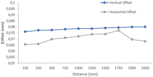
Figure 14. Developed LDR Alignment.
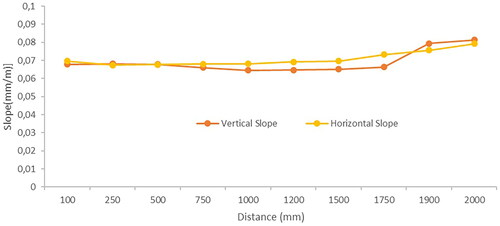
Figure 15. Total alignment integrity chart.
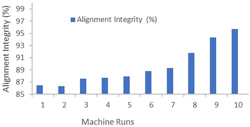
3.2.6. Total machine integrity results
The total machine integrity runs are shown in and summarized in .
Figure 16. Total Machine Integrity Chart.
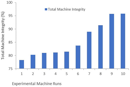
Table 4. Total machine integrity.
3.3. Performance evaluation of the developed mechatronic system
A paired t-test was used to conduct performance evaluation of Integrity Evaluator 1.0 by inputting all the values obtained from the system into an online paired t-test simulator, as shown in and tabulated in . The results showed a 5% level of significance and a 95% confidence level. This is a very impressive result, which shows great repeatability.
Figure 17. Online Paired T-Test Simulator.
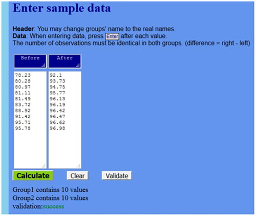
Table 5. Results of performance evaluation on developed mechatronic system.
4. Discussion
From the various remedial actions taken concerning speed, pressure and alignment modules using the lathe machine as case study, the total machine integrity improved from 78.24% to 95.78%. This is a tremendous improvement in total machine integrity. This result is also expected, as it is an old lathe. This result obtained from the developed mechatronic system using integrated data for improved performance from attached sensors also extended the service life of the machine tools. This was also supported by recent literature that implemented a model for digital retrofit and increased machine service life by a further 5–10 years, which also added to resource savings and a more efficient operation (Kröll & Cseh, Citation2023). The accuracy assessment obtained after the connection of the integrity evaluator 1.0 from shows that the tolerance grade, which was synonymous with the machining accuracy, had lower tolerance grades between IT 7 and IT 9 compared to a value of IT 11–IT 13 when Integrity evaluator 1.0 was not connected. Lower tolerance grades indicating higher machining accuracy were observed when integrity evaluator 1.0 was used. also shows impressive improvement in surface quality using the surface roughness of the workpiece whose finish for turning operation ranged between 0.81 µm and 0.9 µm at recommended high speed ranging from 760 rpm, 1040 rpm and 1490 rpm.
Table 6. Machine tool accuracy assessment.
Varying the lathe cutting speed within the low-, medium- and high-speed ranges as shown in resulted in improved surface finish thereby mitigating built-up edges and facilitating better chip evacuation. However, excessive cutting speeds were observed to cause tool wear and thermal issues, hence INTEGMAC was used to optimize the optimum cutting speed to enhance machining performance.
Increasing the cutting feed and cutting depth rates also enhanced surface finish by encouraging chip breakage reducing cutting forces and reducing the number of passes needed to achieve the desired dimension, respectively. However, excessively high feed rates were associated with tool deflection, chatter or inadequate chip formation and deeper cuts increased cutting forces and vibration, potentially affecting the surface finish.
Optimizing coolant pressure and directing it into the cutting region improved cooling and lubrication effectiveness, consequently reducing heat and friction while flushing away chips. This significantly enhanced surface quality and tool life, thereby improving machine tool integrity. Furthermore, implemented remedial actions recommended by INTEGMAC, coupled with alignment checks from the alignment system, enhanced rigidity and stability, thereby improving machining performance.
Achieving optimal functions with our developed INTEGMAC software involved deciding the ideal cutting speed, feed rate and depth of cut, which were noticed to be dependent on the workpiece material, desired surface finish, tool rigidity and machine stability. Meticulous adjustments from conducted experimental results in ensured optimal surface roughness and machining performance, consequently enhancing machine tool integrity.
Furthermore, the ISO 286 standardized tolerance grade was used to detect any deviations in machined shaft dimensions, and its compliance ensured the upgraded machine tool with Integrity Evaluator met the required standards. The ISO 286 standard helped define the acceptable level of precision achieved during the conventional machine tool upgrade. This validated the upgraded machine tool delivered the desired precision and accuracy during machining. Additionally, adaptive control systems in the INTEGMAC software monitored accurate feedback of machining parameters from sensors and recommended remedial actions to help compensate for the deviations from the expected dimension. This ensured compliance with ISO 286 thereby improving the integrity of the machine tool.
The monitoring of the cutting speed was also very important, as it had a great determining effect on machine accuracy determination. This was supported by a previous study that confirmed that cutting speed and the workpiece material type were the predominant factors influencing surface roughness, which determines the machining accuracy of the machine tool (Abdullah et al., Citation2016). Summarily, this study has devised a strategy for adding value to conventional machine tools to enhance continued relevance in the machine tools industry. This will definitely support industrialization in developing economies and at the same time conserve foreign exchange by reducing investment in CNC machine tools.
5. Conclusions
A model was developed to determine the structural and operational integrity of machine tools and was used to develop a mechatronic system for automatic data collection and processing procedures. The integrity of the developed mechatronic system was evaluated in a lathe machine, and its performance was obtained using an online paired t-test. Composite parameters were singled out, possible areas of locating measurement probes and sensors on the machine tool were determined, and the sensors needed to measure these parameters were also applied. The formulation of the integrity model was also derived together with a workable flowchart and software algorithm. A Python programming language software named InteGMac was developed to analyze the integrity of the machine tool.
The mechatronic system named Integrity Evaluator 1.0 was developed from the developed model to determine the integrity of machine tools. This was achieved by designing and developing a mechatronic circuitry into three different areas, namely, the speed module, the pressure module and the alignment module. The speed module measured the spindle speed and electric motor speed using infrared speed sensors connected to an Arduino mega 2560 microcontroller. The pressure module measured both the hydraulic and pneumatic pressure readings of the machine tool using hydraulic and pneumatic pressure transducers attached to the pressure line of the machine tool. The alignment module measured both the headstock/tailstock alignment and the headstock/toolpost alignment with the aid of a LDR grid system developed in-house during the research and a laser transmitting and receiving module together with an ultrasonic sensor for lathe center readings. An Arduino programming sketch code was also developed to power the Arduino Mega 2560 microcontroller to automatically obtain all the sensor readings and relay them to the InteGMac software for integrity analysis and possible improvement.
The associated software proved useful in implementing the model in the case study and clearly showed the robustness and effectiveness of the model and the mechatronic system, as the developed software responded well to the sensor readings and analyzed the real-time upgrade of the machine tool. The real-time monitoring of the mechatronic system was supported to have the same result in a similar study that effectively predicted countermeasures in the form of remedial actions carried out by Jedrzejewski and Kwasny (Citation2017). The performance of the system also showed an improved speed and automatic mode of data collection of integrity parameters on the machine tool after carrying out recommended remedial actions. It further improved the total machine integrities of the Boxford 11-30 Industrial Lathe from 78.24% to 95.78%.
Thus, this solution finds application in the machine tool industry and can also be extended to other industrial machines. The study also provides a practical guided approach by which the versatility of conventional machine tools can be upgraded using a mechatronic approach. The study contributes both in theory and practice to the existing knowledge on the digitalization of legacy machines to promote their functionality and adaptability to the dynamic customer demands and production requirements on the shop floor. The study is limited to the evaluation of the proposed approach on machine tools using only the speed, pressure and alignment parameters. Future works can consider the integration of other cogent parameters, such as vibration and temperature.
6. Recommendations
The following recommendations were made from this study:
The developed mechatronic system can be used not only on lathe machines but also on other machine tools, such as the milling machine, drilling machine and shaping machine if reconfigured for integrity analysis.
Improvements can be made in the area of automatically actuating remedial actions using mechatronic actuators to minimize machine operator intervention and consider the effects of the adjusted operating parameters. Advanced deep learning algorithms can be incorporated to learn from past experiences and optimize its decision-making process of recommending remedial actions.
Machine shop owners may adopt this system in their various machine tools to quickly assess the performance and the possible degree of accuracy.
Future works should focus more on environmental factors such as the time of measurement and working conditions of conducting test runs. Measurements should always be conducted in a controlled and monitored environment by measuring other room parameters, such as humidity and room temperature.
Author contributions
O. A. Aderoba and O. A. Dahunsi: conceptualization. O. A. Aderoba, B. Kareem and O. A. Dahunsi: methodology. O. A. Aderoba: software. O. A. Aderoba and B. Kareem: validation. O. A. Aderoba, B. Kareem, O. A. Dahunsi and O. A. Awopetu: formal analysis. O. A. Aderoba, K. Mpofu, B. Kareem, O. A. Dahunsi and O. A. Awopetu: investigation. O. Aderoba and K. Mpofu: resources. O. A. Aderoba: data curation. O. A. Aderoba and O. A. Dahunsi: writing – original draft preparation. O. A. Aderoba and I. A. Daniyan: writing – review and editing. O. A. Aderoba and I. A. Daniyan: visualization. B. Kareem, O. A. Dahunsi and O. A. Awopetu: supervision. O. A. Aderoba and B. Kareem: project administration. O. A. Aderoba and K. Mpofu: funding acquisition.
Consent form
All the authors agreed to publish this paper.
Code availability statement
All code of this study is available from the corresponding author upon reasonable request.
Acknowledgement
My academic mentor in the person of Prof. Adeyemi Adegbemisipo Aderoba, together with the following engineering department and workshops, is acknowledged for their immense contributions. They are:
Department of Industrial Engineering, Tshwane University of Technology, Pretoria, South Africa
The Federal University of Technology Engineering Workshop, Akure, Nigeria.
Elizade University Engineering Workshop, Ilara-Mokin, Ondo State, Nigeria.
Besade Engineering Workshop, Ondo, Nigeria.
Don Bosco Engineering Workshop, Ondo, Nigeria.
Afe Babalola University Engineering Workshop, Ado-Ekiti, Nigeria.
Data availability statement
The data that support the findings of this study are available from the corresponding author upon reasonable request.
Disclosure statement
The authors declare that they have no conflicts of interest.
Additional information
Funding
Notes on contributors

Olugbenga Adegbemisola Aderoba
Olugbenga Adegbemisola Aderoba graduated with a B.Eng in Mechanical Engineering from the Federal University of Technology, Akure (FUTA) Nigeria in 2008 and obtained a Master of Engineering (M.Eng) in Industrial Engineering and a Ph.D also from the same Federal University of Technology, Akure, Nigeria in 2014 and 2019, respectively. He is a registered Engineer with the Council for Regulation of Engineering in Nigeria (COREN) and a Corporate Member of the Nigeria Society of Engineers (MNSE). He has contributed to the development of engineering in terms of successfully implementing various engineering projects and in conducting novel researches. He has attended many International Conferences and served creditably. His research areas include Mechatronics System Designs, Machine Tools, Manufacturing Engineering, Automation, Robotics, and Artificial Intelligence. He is currently a postdoctoral research fellow at the Tshwane University of Technology, Pretoria.

Khumbulani Mpofu
Khumbulani Mpofu is a distinguished researcher and academic specializing in Industrial Engineering at the Tshwane University of Technology, Pretoria, South Africa, currently holding the prestigious Gibela Research Chair in Manufacturing and Skills Development. With a career spanning back to 2004, he has showcased a deep passion for Industrial Engineering, earning recognition as an NRF-rated researcher. Prof Mpofu’s expertise encompasses advanced manufacturing technologies, knowledge-based systems, and the application of robotics in manufacturing. His Master’s studies focused on the computer aspects of the manufacturing industry, contributing to a cleaner production project. In his doctoral work, he designed a Knowledge-Based System for Reconfigurable Manufacturing, showcasing his commitment to addressing diverse manufacturing challenges, from environmental concerns to integrating information systems in manufacturing.

Buliaminu Kareem
Buliaminu Kareem, a distinguished professor in Industrial and Production Engineering at the Federal University of Technology, Akure, Nigeria, holds a Ph.D. in Industrial Engineering earned in August 2004, an M.Eng. in Production Engineering obtained in January 1999, and a Bachelor of Engineering (B.Eng.) in Mechanical Engineering awarded in March 1994. His extensive skills and expertise encompass areas such as Machine Tools, Six Sigma, Process Engineering, Process Optimization and Modeling, Simulation Engineering, Modeling and Simulation, Parameter Optimization, Sensitivity Analysis, and Process Integration.

Olurotimi Akintunde Dahunsi
Olurotimi Akintunde Dahunsi, a distinguished professor in the Department of Mechatronics Engineering at the Federal University of Technology, Akure, Nigeria, possesses a rich academic background. He earned his B.Eng. and M.Eng. Degrees in Mechanical Engineering from the Federal University of Technology, Akure, Nigeria, and completed his PhD in Mechanical Engineering at the University of Witwatersrand, Johannesburg, South Africa. Proficient in mechatronics systems design, intelligent control, Condition Monitoring Techniques, and vibration mechanics, Prof. O. A. Dahunsi brings a comprehensive skill set to applications in mechatronics and mechanical engineering, with a particular emphasis on manufacturing and dynamic systems.

Olayinka Oladele Awopetu
Olayinka Oladele Awopetu is a distinguished Professor in the Department of Industrial and Production Engineering at The Federal University of Technology, Akure. His research focuses on Metal Cutting, Chip Formation, Machine Tools, Manufacturing Technology, and Waste-to-Wealth endeavors such as the conversion of agro wastes into briquettes and particle boards. Proficient in Materials Science, his expertise encompasses Titanium Microstructure, Advanced Materials, High-Temperature Materials, Material Testing, Titanium Alloys, Alloys Machining, Machine Tools, and Mechanical Properties. He earned his Ph.D. in Mechanical Engineering in 2012 from the Department of Mechanical Engineering at The Federal University of Technology, Akure. Furthermore, he holds an M.Sc. in Mechanical Engineering (1989) from the Department of Manufacturing Technology, Volgograd Polytechnic Institute, Volgograd, Russia; a Postgraduate Diploma (PGD) in Education (1989) from the Department of Linguistics, Volgograd Polytechnic Institute, Volgograd, Russia; and a National Diploma (ND) in Mechanical Engineering (1982) from the Department of Mechanical Engineering, Ondo State Polytechnic, Owo, Ondo State, Nigeria.

Ilesanmi Afolabi Daniyan
Daniyan Ilesanmi Afolabi is an associate professor at Achievers University, Owo, Nigeria. He was a Postdoctoral Research Fellow at the Department of Industrial Engineering at Tshwane University of Technology, Pretoria, South Africa. He earned his Doctor of Philosophy (Ph.D.) in Mechanical Engineering with a focus on Production Engineering & Renewable Energy in 2017. Additionally, he holds a Master of Engineering (M.Eng.) in Mechanical Engineering with a specialization in Production Engineering, where he achieved the top rank in 2012. Associate Professor Daniyan also obtained a Bachelor of Technology (B.Tech.) in Chemical Engineering in 2008. His expertise and research interests encompass Production Engineering, Advanced and Additive Manufacturing, Reconfigurable Manufacturing Systems, Automation and Robotics, and Renewable Energy.
References
- Abdullah, R., Mahrous, A., & Barakat, A. (2016). Surface quality of marble machined by abrasive water jet. Cogent Engineering, 3(1).
- Al-Maeeni, S. S. H., Kuhnhen, C., Engel, B., & Schiller, M. (2020). Smart retrofitting of machine tools in the context of industry 4.0. Procedia CIRP, 88, 369–374. https://doi.org/10.1016/j.procir.2020.05.064
- Alqoud, A., Schaefer, D., & Milisavljevic-Syed, J. (2022). Industry 4.0: A review of digital retrofitting solutions for legacy manufacturing systems. Advances in Manufacturing Technology XXXV, 25, 3–9.
- Ashmawy, M., Elsheikh, A., & Elkassas, A. (2023). A review of cooling and lubrication techniques for machining difficult-to-cut material. Journal of Engineering Research, 7(1), 4. https://doi.org/10.21608/erjeng.2023.183248.1134
- Babalola, S. A., Mishra, D., Dutta, S., & Murmu, N. C. (2023). In-situ workpiece perception: A key to zero-defect manufacturing in Industry 4.0 compliant job shops. Computers in Industry, 148, 103891.
- Baur, M., Albertelli, P., & Monno, M. (2020). A review of prognostics and health management of machine tools. International Journal of Advanced Manufacturing Technology, 107, 2843–2863.
- Bleicher, F., Biermann, D., Drossel, W.-G., Moehring, H.-C., & Altintas, Y. (2023). Sensor and actuator integrated tooling systems. CIRP Annals, 72(2), 673–696. https://doi.org/10.1016/j.cirp.2023.05.009
- Bolton, W. (2015). Mechatronics: Electronic control systems in mechanical and electrical engineering. Pearson Education, p. 3.
- Budak, E., Matsubara, A., Donmez, A., & Munoa, J. (2022). Mechanical interfaces in machine tools. CIRP Annals, 71(2), 647–670. https://doi.org/10.1016/j.cirp.2022.05.005
- Cunha, J., Batista, N., Cardeira, C., & Melicio, R. (2021). Upgrading a legacy manufacturing cell to IoT. Journal of Sensor and Actuator Networks, 10(4), 65. https://doi.org/10.3390/jsan10040065
- de Sá Só Martins, D. H. C., Viana, D. P., de Lima, A. A., Pinto, M. F., Tarrataca, L., e Silva, F. L., Gutiérrez, R. H. R., de Moura Prego, T., Monteiro, U. A. B. V., & Haddad, D. B.(2021). Diagnostic and severity analysis of combined failures composed by imbalance and misalignment in rotating machines. International Journal of Advanced Manufacturing Technology, 114, 3077–3092.
- Dias, A. L., Turcato, A. C., Sestito, G. S., Brandao, D., & Nicoletti, R. (2021). A cloud-based condition monitoring system for fault detection in rotating machines using PROFINET process data. Computers in Industry, 126, 103394.
- Feng, C., & Huang, S. (2020). The analysis of key technologies for sustainable machine tools design. Applied Sciences (Switzerland), 10(3), 731. https://doi.org/10.3390/app10030731
- García-Martínez, E., Miguel, V., Martínez-Martínez, A., Manjabacas, M. C., & Coello, J. (2019). Sustainable lubrication methods for the machining of titanium alloys: An overview. Materials, 12(23), 3852. https://doi.org/10.3390/ma12233852
- Goman, V. V. (2020). Prospects of upgrade of the main drives of CNC machine tools using mechatronic modules. KnE Engineering, 5(3), 36–42. https://doi.org/10.18502/keg.v5i3.6755
- Goodall, P., Pantazis, D., & West, A. (2020). A cyber physical system for tool condition monitoring using electrical power and a mechanistic model. Computers in Industry, 118, 103223.
- Guan, K., Sun, Y., Yang, G., & Yang, X. (2023). Hybrid decision-making-method-based intelligent system for integrated bogie welding manufacturing. Applied System Innovation, 6(1), 29. https://doi.org/10.3390/asi6010029
- Ilari, S., Carlo, F. D., Ciarapica, F. E., & Bevilacqua, M. (2021). Machine tool transition from industry 3.0 to 4.0: A comparison between old machine retrofitting and the purchase of new machines from a triple bottom line perspective. Sustainability (Switzerland), 13(18), 10441. https://doi.org/10.3390/su131810441
- Jedrzejewski, J., & Kwasny, W. (2017). Development of machine tools design and operational properties. International Journal of Advanced Manufacturing Technology, 93, 1051–1068.
- Jeerapongudom, T., Anwar, S., & Che, B. (2022). Design and development of mini CNC machine for high performance machining. EasyChair Preprint No. 9104. EasyChair.
- Jiang, Y., Drescher, B., Wittstamm, M., Hu, C., Clemens, F., Wang, W., & Stich, V. (2022, May 17–20). Tool wear prediction upgrade kit for legacy CNC milling machines in the shop floor [Paper presentation]. 3rd Conference on Production Systems and Logistics (CSPL 2022), Vancouver, BC, Canada (pp. 131–140).
- Keshav Kolla, S. S. V., Lourenço, D. M., Kumar, A. A., & Plapper, P. (2022). Retrofitting of legacy machines in the context of Industrial Internet of Things (IIoT). Procedia Computer Science, 200, 62–70.
- Keshava, K. G., & Sree Rajendra, C. K. K. R. (2021). Retrofitting of CNC bench milling machine with raspberry Pi. International Research Journal of Engineering and Technology (IRJET), 8, 3937–3941.
- Kröll, M., & Cseh, C. (2023). Implementation model for digital retrofit for sustainable production. Procedia Computer Science, 217, 486–494.
- Li, K. Y., Luo, W. J., & Wei, S. J. (2020). Machining accuracy enhancement of a machine tool by a cooling channel design for a built-in spindle. Applied Sciences (Switzerland), 10(11), 3991. https://doi.org/10.3390/app10113991
- Li, Z., Wang, Y., & Wang, K. (2019). A deep learning driven method for fault classification and degradation assessment in mechanical equipment. Computers in Industry, 104, 1–10.
- Lindfield, G., Penny, J., & Analyzing, D. (2019). Numerical methods using Matlab, Fourth Edition, Academic Press, Chapter 7, Elsevier (pp. 329–381). https://linkinghub.elsevier.com/retrieve/pii/B9780128122563000166
- López de Calle, K., Ferreiro, S., Arnaiz, A., & Sierra, B. (2019). Dynamic condition monitoring method based on dimensionality reduction techniques for data-limited industrial environments. Computers in Industry, 112. (November Issue).
- Mohamed, A., Hassan, M., M’Saoubi, R., & Attia, H. (2022). Tool condition monitoring for high-performance machining systems – A review. Sensors, 22(6), 2206. https://doi.org/10.3390/s22062206
- Neugebauer, R., Denkena, B., & Wegener, K. (2007). Mechatronic systems for machine tools. CIRP Annals – Manufacturing Technology, 56, 657–686.
- Oezkaya, E., Michel, S., & Biermann, D. (2022). Experimental and computational analysis of the coolant distribution considering the viscosity of the cutting fluid during machining with helical deep hole drills. Advances in Manufacturing, 10, 235–249.
- Patole, P. B., & Kulkarni, V. V. (2017). Experimental investigation and optimization of cutting parameters with multi response characteristics in MQL turning of AISI 4340 using nano fluid. Cogent Engineering, 4(1).
- Pelayo, G. U., Olvera-Trejo, D., Budak, E., & Wan, M. (2023). Special issue on machining systems and signal processing: Advancing machining processes through algorithms, sensors and devices. Mechanical Systems and Signal Processing, 182, 109575.
- Peng, J., Yin, M., Cao, L., Liao, Q., Wang, L., & Yin, G. (2023). Study on the thermally induced spindle angular errors of a five-axis CNC machine tool. Advances in Manufacturing, 11, 75–92.
- Pimenov, D. Y., Mia, M., Gupta, M. K., Machado, A. R., Tomaz, Í. V., Sarikaya, M., Wojciechowski, S., Mikolajczyk, T., & Kapłonek, W. (2021). Improvement of machinability of Ti and its alloys using cooling-lubrication techniques: A review and future prospect. Journal of Materials Research and Technology, 11, 719–753. https://doi.org/10.1016/j.jmrt.2021.01.031
- Sparham, M., Sarhan, A. A. D., Mardi, N. A., & Hamdi, M. (2014). Designing and manufacturing an automated lubrication control system in CNC machine tool guideways for more precise machining and less oil consumption. International Journal of Advanced Manufacturing Technology, 70, 1081–1090.
- Sutopo, S., Setiadi, B. R., & Hanzla, M. (2020). Upgrading manual turning machine towards IoT-based manufacturing. Jurnal Pendidikan Teknologi Dan Kejuruan, 26(2), 155–161. https://doi.org/10.21831/jptk.v26i2.27334
- Tsai, P. C., Cheng, C. C., Chen, W. J., & Su, S. J. (2020). Sensor placement methodology for spindle thermal compensation of machine tools. International Journal of Advanced Manufacturing Technology, 106, 5429–5440.
- Uhlmann, E., Lang, K.-D., Prasol, L., Thom, S., & Peukert, B. (2017). Sustainable solutions for machine tools. In R. Stark, G. Seliger, & J. Bonvoisin (Eds.), Sustainable manufacturing. Sustainable production, life cycle engineering and management (pp. 47–69). Springer.
- Uhlmann, E., Thom, S., & Ehricke, M. (2017). Application of spindle speed increaser as sustainable solution to upgrade machine tools. Procedia Manufacturing, 8, 680–685. https://doi.org/10.1016/j.promfg.2017.02.087
- Wan, S., Li, D., Gao, J., Roy, R., & Tong, Y. (2017). Process and knowledge management in a collaborative maintenance planning system for high value machine tools. Computers in Industry, 84, 14–24.
- Wu, C., Wang, Q., Fan, J., & Pan, R. (2020). A novel prediction method of machining accuracy for machine tools based on tolerance. The International Journal of Advanced Manufacturing Technology, 110, 629–653. https://doi.org/10.1007/s00170-020-05762-4
- Zhao, Y. (2020). The application research of mechatronics technology based on computer in construction machinery. Journal of Physics: Conference Series, 1574, 012060. https://doi.org/10.1088/1742-6596/1574/1/012060
- Zhao, Z., Lin, P., Shen, L., Zhang, M., & Huang, G. Q. (2020). IoT edge computing-enabled collaborative tracking system for manufacturing resources in industrial park. Advanced Engineering Informatics, 43, 101044. https://doi.org/10.1016/j.aei.2020.101044
- Zheng, C., Le Duigou, J., Bricogne, M., & Eynard, B. (2016). Multidisciplinary interface model for design of mechatronic systems. Computers in Industry, 76, 24–37.