
Abstract
Power Electronics (PE) is pivotal in fostering renewable energy. However, focusing on usage efficiency shifts environmental impacts across its life cycle, leading to excessive resource extraction and waste accumulation. Integrating environmental impact indicators in PE development is crucial for informed design decisions. Nevertheless, the current literature lacks the provision of adequate understanding of the PE product development process for successful ecodesign in PE industry. To effectively tackle the industrial integration aspect of ecodesign that enable functional and system innovation, this study employs empirical research, combining literature analysis with in-depth interviews with PE designers. Requirements for an ecodesign support to integrate ecodesign practices into the Product Development Process (PDP) of PCB-based Power Electronic Components (PECs) is proposed in this paper based on the interview results. These specifications are delineating the necessary working and decision-making steps. Subsequently, a parameterized Functional Block-based Life Cycle Analysis (FB-LCA) model is proposed under the requirement. A five-step methodology is proposed to operationalise the implementation of the FB-LCA model, aiming to supporting the definition of functional structure, configuration of technical solutions and choice of hardware components by considering environmental impacts generated all along life cycle, from manufacturing, transport, use, circularity scenario, end-of-life .The case study of a PCB-based boost converter design is conducted in collaboration with a PE engineer to test the practical implementation of FB-LCA model.
REVIEWING EDITOR:
1. Introduction
Power Electronics (PE) have become the key technology for achieving a more renewable energy mix in our contemporary societies (Popović-Gerber et al., Citation2012). Integrating Power Electronics Converters (PEC) into various systems has facilitated a wide range of applications and enabling efficient energy usage (Popović-Gerber et al., Citation2012). For instance, on the energy production side, PECs are used to interface the main electricity network with advanced renewable energy sources, such as wind turbines and photovoltaic panels; on the energy consumption side, they are used for converting and distributing energy to a variety of devices, including but not limited to Electrical Vehicles (EVs), residential heating, air conditioning, household appliances, and small electronic devices such as laptop chargers (Falck et al., Citation2018). To comply with the Ecodesign Directive (Directive 2009/125/EC of the European Parliament and of the Council of 21 October 2009 Establishing a Framework for the Setting of Ecodesign Requirements for Energy-Related Products (Text with EEA Relevance), 2009), the PE community has been actively engaged in enhancing the energy efficiency of PE converters through ecodesign initiatives (e.g. Borres et al., Citation2019; Popescu et al., Citation2017). However, the recent surge in functionalities witnessed in the past few decades indicates a distinct rebound effect occurring at the hardware level, where efficiency optimizations are offset or countered (Pirson et al., Citation2023). Rapid technological advancements lead to the obsolescence of electronic products, a trend that is expected to result in a staggering 74.7 million tons of electronic waste by 2030 (Forti et al., Citation2020). The majority of PECs are disposed of in landfills or incinerated (Forti et al., Citation2020), which can have severe environmental consequences due to the release of significant amounts of toxic pollutants. These pollutants include polychlorinated biphenyls found in passive components, PVC from insulation cables, brominated flame retardants used in printed circuit boards (PCBs), as well as heavy metals such as lead, cadmium, and mercury (Javier Hurtado Albir & Antonio Carrasco Hernández, Citation2011).
In response to the challenges posed by excessive material consumption and waste accumulation, the European Union’s Circular Economy Action Plan (CEAP) in 2020 has identified the circular economy as a pivotal strategy (A New Circular Economy Action Plan For a Cleaner & More Competitive Europe, Citation2020). Circular economy involves extending the lifespan of products and their components through circularity strategies such as repair, reuse, remanufacture, and recycling (Bauer et al., Citation2016; Potting et al., Citation2017). To build upon the previous ecodesign directive, the European Commission introduced a proposal for the ‘Eco-design Regulation for Sustainable Products (ESPR)’ in March 2022 (Directorate-General for Environment, Citation2022). This proposal’s overarching goal is to establish ecodesign requirements that promote sustainability and place a strong emphasis on integrating circularity principles into the design of Energy-related Products (ErP) (Directorate-General for Environment, Citation2022). This transition toward a circular economy is primarily guided by ecodesign practices, aligning with the principle of Life Cycle Thinking (LCT) (IEC 62430, 62430, Citation2019). Life Cycle Thinking involves ‘considering the trade-offs between different environmental aspects throughout all life cycle stages’ (IEC 62430, 62430, Citation2019). This principle is imperative to prevent environmental burdens shifting from one life cycle stage to another or from one environmental impact indicator to another one, and therefore take into account multiple life cycles and environmental factors together during the PE product development activities (Multon et al., Citation2012b). In 2020, Rio et al. proposed the Design for Multiple Usages approach to tackle circular economy issues in the context of PE, ultimately reducing the overall adverse environmental impacts of PE products (Rio et al., Citation2020). This initiative was exemplified by the development of a prototype multicell modular power converter at the electrical engineering laboratory (G2ELab) in France (Romano et al., Citation2023), showcasing its potential for reuse and its improvements on environmental performance (Rahmani et al., Citation2021). Despite these promising developments, a recent study revealed that the operational and effective implementation of ecodesign within the PE industry remains limited (Fang et al., Citation2023). During interviews with PE designers, a significant challenge emerged: the lack of a circular life cycle model coupled with relevant environmental indicators to guide their ecodesign decisions and trade-off assessments. This deficiency can, in turn, hinder considerations of impact transfer across various life cycle stages, while also obscuring the environmental advantages associated with choosing components that could potentially have a second life (Fang et al., Citation2023a).
The inclusion of environmental aspects in evaluating product functions is essential while also meeting the performance requirements for the client (Millet, Citation2003). To effectively implement ecodesign, actions taken in product development must integrate environmental considerations alongside other traditional product requirements, such as functionality, safety and cost (Bovea & Pérez-Belis, Citation2012; Johansson, Citation2002). Concrete contextual information about the product development process is indeed crucial for improving ecodesign implementation (Diaz et al., Citation2021).
Based on this literature results, this paper investigates the contextual specificities of PE PDP to address the 'industrial integration aspect’ of ecodesign methodology. This focus on industrial integration represents the novelty of this study compared to previous literature finding, which predominantly concentrates solely on the products’ technology developments to ecodesign them. The objective of this research is to propose a methodology that assists PE designers in evaluating, analyzing, and enhancing the environmental and circularity performance of PEC throughout the entire PDP.
Thus, in this study, the following research questions are formulated:
RQ1: What are the specific contextual factors involved in the design process of PCB based PEC: key actors, design activities, design criteria, design tools, created product information?
RQ2: How to effectively implement ecodesign for addressing environmental and circularity constraints during the PCB-based PEC product development process?
The following section presents the Design Research Methodology followed in this research (Section 2). A Descriptive Study is conducted, combining literature analysis and empirical studies. Through the observation of PE designers, the authors clarify contextual information for integrating the PE ecodesign framework (Section 3) to address RQ1. In Section 4, a Functional Block based Life Cycle Analysis model (FB-LCA model) and its implementation process for PCB-based PEC ecodesign is proposed to address RQ2. The FB-LCA model is applied to a case study of a boost converter ecodesign. This section discussed on the added value and three main limitations of the methodology. Finally, Section 5 concludes this research paper by outlining contributions and indicating future research axes that urging the operationalization of a systematic ecodesign integration in PCB-based products in the worldwide diversity of today industrial contexts.
2. Material and research method
To carry out this study, the Design Research Methodology (DRM) was used as a reference (Blessing & Chakrabarti, Citation2009). The present paper incorporates the iterative phases of the DRM research process, namely:
The comprehensive Descriptive Study-I (DS-I) was based on literature analysis and empirical research process aimed at describing the current PCB based PE product development process, identifying design activities in each step, and clarifying the requirement to the methodology to incorporate the specific ecodesign working and decision-making steps for PCB-based Power Electronic Converter.
The Prescriptive Study-I (PS-I) proposed a Functional Block based Life Cycle Analysis model (FB-LCA model) that establishing the cause-effect chain between the choice of technical parameters and environmental consequences (). A five-step methodology () is proposed to operationalise the implementation of the FB-LCA model, aiming to support the definition of functional structure, configuration of technical solutions and choice of hardware components by considering environmental impacts generated all along life cycle, from manufacturing, transport, use, circularity scenario, end-of-life.
The comprehensive Descriptive Study-II (DS-II) that criticized the effect of the prescribed FB-LCA model involved in the ecodesign process to overcome the issue of ecodesign integration in PE PDP, in particular the cause-to-effect link between design parameters and environmental-technical performance addressed for each designed function to fulfill within circular life cycle scenarios. The case study of a PCB based boost converter design was conducted in collaboration with a PE engineer to test the practical implementation of FB-LCA model. The added value and limitations of the methodology were analyzed, indicating directions for future improvements.
3. State of the art
3.1. Lacks in PE ecodesign approaches
In the previous study, Fang and Romano et al. (Citation2023) reported a scoping review which provides an overview of the up-to-date progress in PE ecodesign (Fang et al., Citation2023). Four ecodesign approaches are identified from current PE design research: (1) energy efficiency optimization, (2) eco-sizing (3) eco-reliability, (4) multi usage life cycle design (). The literature review results reveal a significant gap in available research in this area. Most current research only focuses on optimizing energy efficiency during the usage stage of PECs, with only a few studies taking a comprehensive approach that considers all stages of the PEC's life cycle and its various environmental impacts (Fang et al., Citation2023). The limited number of case studies in the ecodesign of PEs suggests that these approaches have not been further developed or implemented in academia nor in industry (Fang et al., Citation2023).
Table 1. Eco-design approaches developed and applied in PE design research (Fang and Romano et al., Citation2023).
3.2. Contextual factors in PCB-based PE product development process
Previous section showed that the implementation of ecodesign in the specific Product Development Process of Power Electronics Converter has not been addressed yet in the literature. This lack of theoretical foundations motivated the empirical study based on industrial practices observations and interviews (Fang et al., Citation2023). Ten interviews were conducted to specifically examine the design process of PEC, the specific contextual needs of PE designers to implement ecodesign activities, and the potential barriers they face (Fang et al., Citation2023). In this section, the main findings of this empirical research are detailed and significantly developed to improve challenges understanding.
The list of interviewee profiles is presented in . Interviewees were contacted by email and informed that the interview content would anonymously support the research project. Informed written consent has been obtained from all participants for the study. All interviews were conducted online or in-person from September 2022 to January 2023. Five questions covering twenty-four prompting aspects (cf. Appendix A) guided data collection of the final interviews.
Table 2. Profiles of interviewees (adapted from [Fang et al., Citation2023]).
3.3. PCB-based PEC product development process
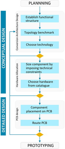
Contextual information is crucial to the success of ecodesign implementation (Diaz et al., Citation2021), and the lack of universal PEC design methodology has motivated to formalize a PDP framework based on interviews conducted in this research. summarizes a generic PEC-PDP), that builds the framework to implement ecodesign. First, interviewees confirmed that PEC industrial design process could be divided into three main stages after validating the functional specifications with clients: conversion architecture design, hardware allocation, and PCB design (). The first two stages are commonly referred to as conceptual design in engineering design, while PCB design belongs to detailed design (Pahl & Beitz, Citation1996). Through the iterative design process of these three stages PDP, the final design documentation is obtained, leading to the prototype and bench test phase. The contextual factors of each stage were clarified through interviews and validated by PE designers. This includes identifying the actors involved in each step, design criteria considered by the actors, their design activities and design tools used, specifying deliverables and created information in each step.(Fang et al., Citation2023).
Figure 1. Generic product development process of power electronics converters.
3.4. Key moments to implement ecodesign in PCB-based PEC design process: needs, opportunities and potential barriers
Interviewees addressed three key moments to integrate circularity and environmental constraints into the PDP: at the conversion structure design, hardware allocation, and PCB design stages ().
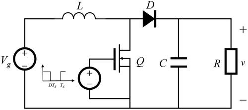
Conversion structure design is the first stage of PCB-based PEC design. During this stage, PE designer defines the functional structure of the PCB-based PEC and configures the technical solutions to satisfy the required functions specified by clients, that is commonly called the ‘pre-sizing step’. The deliverable of this step is presented in a topology circuit diagram (), while indicating the technical characteristics required for each electronic component. During this stage, PE designers expressed that it would be necessary to analyse the potential environmental impacts of the functional structure and technical configuration to support decision-making (INT1, INT3, INT4, INT7, INT9). No life cycle model for PECs circularity scenario was generated in PDPs (encompassing repair, reuse, and remanufacturing). Circular lifecycle modelling appears to be lacking in practice to inform PE designers of the design levers to reduce environmental impacts in the circular lifecycle stage. The ecodesign literature argues that integrating several environmental indicators in the design assessment of the product provides quantitative arguments to designers to identify hotspots among lifecycle stages, aligned (or not) to the functional blocks of the system they develop, and that has the power to initiate functional innovations. By contrast, the current PEC PEP process allows for the rebuttal of functional specifications with environmental arguments before beginning optimization at the hardware level. A preliminary LCA appears to be lacking to obtain a whole picture of the environmental impacts of designed products. This lack leads to a sub-optimization and trade-offs that prevent radical eco-innovation. At the pre-sizing stage, INT1, INT3, INT9 suggested providing understandings about the sensitive component oversizing effect to environmental impacts generations. These practical guidelines would then inform at the next stage the designer in charge of hardware selection.
Figure 2. Topology circuit diagram (example of a boost converter).
Brambila-Macias and Sakao (Citation2021) identified that product designers in manufacturing companies need support from a lifecycle engineer to translate environmental indicators (e.g. kg CO2 eq.) into common engineering language (e.g. to reduce mass, to lower power) (Brambila-Macias & Sakao, Citation2021). This translation is necessary for designers to iterate on technical solutions and achieve specific technical objectives, leading to potential environmental performance improvements. Similar situations have been identified in the PE industry as well: all PE designers interviewed in Fang et al. (Citation2023) admitted their lack of skills to interpret LCA (Life Cycle Assessment) results. Interviewees pointed out that they were not familiar with environmental impact indicators. In addition, they were not able to link their designed functional modules with the technical parameters influencing the environmental impact performance, and therefore not able to iterate on their design solutions.
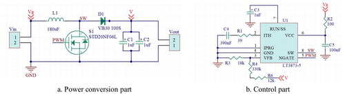
The hardware selection stage follows once conversion structures are defined. During this stage, PE designers size the components, select hardware from suppliers’ catalogue and allocate to each technology (). PE designers need to refer to the available ecodesign methods to be guided in selecting hardware while considering circularity constraints and the potential environmental impacts that would be generated.
Figure 3. Deliverable of hardware selection (Example of a boost converter).
Firstly, INT9 and INT10 argue the need to access to an environmental profile of the available hardware options in the catalogue, comparing their component selection impacts to the average, allowing for informed comparisons to be made. Guidelines on hardware choice to indicate the sensitivity of component oversizing to environmental impacts appear to be required. This suggests that understanding how different hardware components affect the environment differently is crucial for making informed decisions during the selection process.
Secondly, INT1, INT3, INT4, and INT8 suggested that circularity constraints (e.g. component lifetime, disassembly techniques, etc.) need to be considered when choosing hardware, as some components require specific disassembly methods and tools. Design-for-circularity guidelines for PCB-based PEC should be established at the end of this step to be employed in the following 3D layout stage. For instance, the addition of test points to ease diagnostics and preserving enough space around the target component to ensure access for desoldering iron. Various scoring systems and standards have been developed for scoring product circularity under the Circular Economy Action Plans (Dangal et al., Citation2022); Assessment Matrix for ease of Repair (AsMeR) (Bracquene et al., Citation2019); Joint Research Centre Repair Scoring System (RSS) (Sanfelix et al., Citation2019); iFixit 2019 (smartphone repairability scoring system) (Flipsen et al., Citation2019); General methods for the assessment of the ability to repair, reuse and upgrade energy-related products (EN 45554); Label of Excellence for Durable, Repair-Friendly, Designed Electrical and Electronic Appliances (ONR:192012); and French Reparability Index (FRI, 2021). However, the proposed criteria in the repairability index are not specified and adapted to different levels of PEC systems (electronic components, PE assemblies, products). Additionally, the proposed criteria only focus on mechanical disassembly aspects of the product without considering circuit robustness against failures or design that facilitates diagnostics.
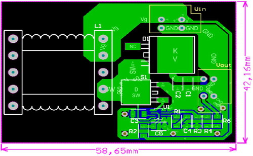
During the PCB design stage, ecodesign methods are needed to assist PE designers in converting schematic nets to physical traces on Printed Circuit Boards (PCBs) (). Several interviewees argued that PE designers need to be supported in organizing the 3D placement of components to meet circularity requirements (e.g. achieve a certain level of repairability (INT1, INT2, INT4, INT5, INT6, INT9)). Given the fact that electronic components on PCB are highly heterogeneous in terms of material content and reliability, methodological supports are required to analyze the different heterogeneity in multiple converter-system-levels.
Figure 4. Deliverable of 3D routing (Example of a boost converter).
Furthermore, the environmental management systems ecodesign standards (e.g. ISO 14006:2020) recommend a detailed Life Cycle Assessment (LCA) to be conducted at this step to assist in making final decisions.
Lastly, the interviews revealed that ensuring a comprehensive and effective ecodesign approach for PE designers, is required to establish a systematic process that integrates seamlessly into the three key design stages that frame their PDP. From the early design stage, PE designers are lacking in support for monitoring environmental performance of the design solutions alongside technical and economic evaluations. Establishing a causal link between technical parameters and their environmental consequences appears crucial for enabling an influential feedback loop between Life Cycle Assessment (LCA) results and technical decision-making within the realm of PE design.
3.5. Requirements for ecodesign support for PCB-based PEC
The previous section described a number of lacks that are preventing any ecodesign integration in PCB-based PEC PDP to occur along the specific activities and during the designer’s decision-making steps. Requirements to overcome some of the main issues observed in the literature and within practices are summarized in .
Table 3. Requirements for ecodesign support for integrating the specific ecodesign working and decision-making steps to the PCB-based PEC PDP.
First, in the conversion architecture design stage, a parameterized LCA model based on the functional structure, including circularity scenarios, is required to support the definition of the functional structure and optimization of technical solutions by considering environmental impacts generated throughout the life cycle, from manufacturing, transport, use, repair, to end-of-life (Requirement #1).
Second, in the hardware allocation stage, a sensitivity analysis model is required for ranking components’ sensitivity to environmental impacts to support the choice of hardware and provide guidelines on the sensitivity of component oversizing regarding environmental impacts (Requirement #2).
Third, at the beginning of the PCB design stage, the PCB-based PEC design’s compatibility with circularity scenario index is required to identify the design guidelines to be followed during PCB routing (Requirement #3).
In addition, throughout the product development process, an Eco-design space and secondary effects analysis model are required to support quantitative evaluation of potential environmental gains and losses for analyzing and visualizing trade-offs (Requirement #4).
An ecodesign application method is required to ensure the effective implementation of the LCA models and circularity guidelines together. The application method should clarify the ecodesign working and decision-making steps to be integrated into the main stage of PCB-based PEC PDP. It should also indicate the models needed and the necessary knowledges required to deploy each ecodesign activity.
4. Integrating ecodesign in PCB based PEC design: a five step method based on functional block life cycle analysis (FB-LCA) model
4.1. Theoretical development of functional block based life cycle analysis model (FB-LCA model)
The clarification of PEC designers’ activities along the PDP (previous section) highlighted the requirement for a potential effective and successful ecodesign implementation that is addressed in this research in a prescriptive study. The proposition is to develop a parameterized LCA model based on the functional structure, including circularity scenarios, to support the definition of the functional structure and optimization of technical solutions by considering multiple environmental impact indicators generated throughout the PEC product lifecycle, from manufacturing, transport, use, circularity scenario, to end-of-life. The originality of this proposition is, on the one hand, the integration of environmental considerations into functional analysis, on the other hand, the development of circular lifecycle modelling of PCB-based PE.
The architecture of the FB-LCA model is based on the functional block tree established through Functional Analysis System Technic (FAST) methodology, expressed by Logical Architecture Diagram (LAD) in SysML () (Holt & Perry, Citation2008). Each technical block presented in is associated with a Block Definition Diagram (BDD) (Holt & Perry, Citation2008) that indicates their functional constraints, technical characteristics of the selected hardware, environmental profile that described in Life Cycle Inventory (LCI) foreground parameters, circularity profile, and cost information ().
Figure 5. FB-LCA model architecture proposed in this research.
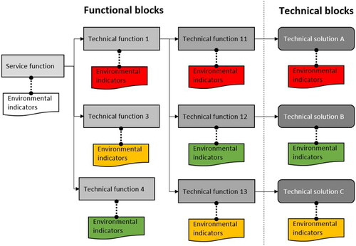
Table 4. Parameters in Block Definition Diagram proposed in the FB-LCA parametric model developed.
This model formalizes a functional block perspective of PEC coupled with environmental impacts indicators. By decomposing the complex PEC functionalities, this model facilitates the environmental impacts performance monitoring across the converters functional blocks and identify ecodesign levers. This integration enables the identification of environmental hotspots and exploration of ecodesign spaces across functional blocks.
4.2. Ecodesign application method of FB-LCA model for PCB based PEC
In this sub section, a five-step ecodesign application method is proposed to implement FB-LCA model for PCB based PEC, illustrated on .
Figure 6. Ecodesign application method for PCB-based PEC.
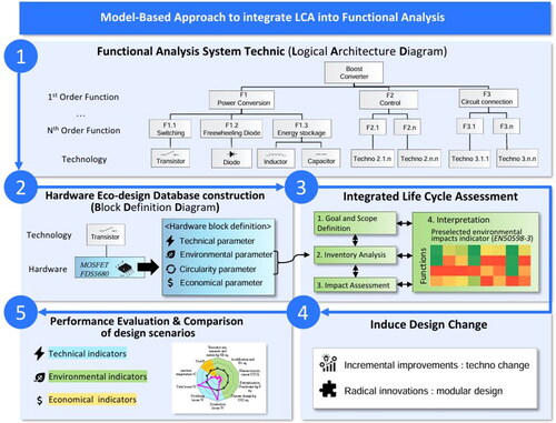
Step (1): conducting a Functional Analysis System Technique (FAST) analysis. This first step focuses on identifying the primary order function of the converter system and decomposing it into sub-functions (e.g. ‘switching’). This process helps PE designers to (a) establish a logical relationship between the system functionalities, (b) to identify all the elementary functions, and (c) to select suitable technologies for each function. The FAST can be supported by a Logical Architecture Diagram (LAD) (e.g. modeled with SysML).
Step (2): a Hardware Eco-design Database elaboration is carried out by the PE designer during the hardware allocation stage. This step consists of constructing a Block Definition Diagram (BDD) for each hardware component selected from the supplier’s catalogue. The BDD should include technical, circularity, environmental, and economic parameters at the hardware level of detail. Particularly, the estimated lifetime of components in a circular scenario of repairs would be detailed by the PE designer, as well as the connector type and the disassembly tools required for that operation. The environmental information would include four crucial parameters, such as the material, energy flows or system unit denominations aligned with LCA database denominations (to allow database interoperability), as well as the quantities associated with the given flow or system unit (e.g.: mass, volume, surface associated with the system unit chosen, such as a PCB), and the manufacturing or assembling processes and system process (e.g.: type and soldering points). Such level of information is indeed essential for constructing the life cycle inventory and model the life cycle of the converter.
Step (3): conducting an integrated Life Cycle Assessment with the support of a LCA analysts, or expert. This step consists of extracting the circularity and environmental information from the Block Definition Diagram (BDD) of the step (2) with the support of PE designer technical explanations, to propose a life cycle inventory model based on the step (1) Logical Architecture Diagram (LAD), and then to conduct a (streamlined) LCA to evaluate the environmental impacts of the system under development. This environmental evaluation is meant to be systematically formalized in the FAST diagram to help PE designer to identify multiple environmental indicators hotspots within the functional structure of the system under development. A heatmap would facilitate hotspots tracking and such complex results visualization (communication). Furthermore, the Life Cycle Assessment (LCA) results represented by a heatmap can be directly displayed into the PEC's 3D layout model to visualize the heterogeneity of environmental impacts indicators from different functions on the PCB.
Step (4): inducing Design Changes by identifying areas for improvements. At this step the PE designers are encouraged to enhance the ecodesign of PEC. This can be achieved through incremental ecodesign actions, such as modifying the hardware by considering the advancement of technologies. The patent analysis method can be applied to support identify ecodesign solutions and build up prospective LCI (Spreafico et al., Citation2023). Alternatively, designers may initiate a radical ecoinnovation, such as rethinking the topology architecture or implementing modular design concepts in converters. These approaches aim to unlock the potential for circular scenarios and promote sustainable practices in the field of PE (Romano et al., Citation2023).
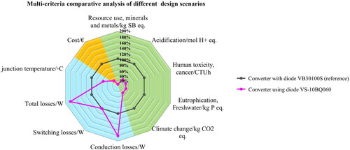
Step (5): Evaluating the design Performances of several Scenarios. New ecodesign may modify technical parameters, and subsequently may influence the system’s eco-technical-environmental performances. Therefore, the fifth step focuses on evaluating such multiple performances of the proposed circular design. Multicriteria decision-making in a comparative analysis process is facilitated by choosing several visualizations (Rio et al., Citation2019). For instance, spidermaps and simple horizontal bar charts, may comprehensively support the assessment of different design options based on multiple criteria. Then the strengths and weaknesses associated with each option can be argued by PE designers themselves during the project review.
Through these five stages, the FB-LCA model is implemented to facilitate the integration of environmental evaluation results (LCA indicators) into the process of functional analysis. The hypothesis is that this process supports the establishment of causal links between technical parameters and environmental consequences, in conjunction with the analysis of technical performance and the life cycle economic costs (i.e. costs of purchasing electronic components, production of the converter, repair/reuse/remanufacture, and the final disposal). These functionalities of FB-LCA are meant to support PE designers to monitor the environmental impacts generated by their design choices along the PDP, including the functional structure definition, technology configuration optimization and the hardware allocation decisions (Functional requirements 1, ).
4.3. Application of FB-LCA ecodesign process through a case study: designing a boost converter
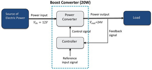
The case study of a boost converter design presented in this section illustrates the practical implementation of FB-LCA model and the potential of applying FB-LCA model to support the integration of circularity and environmental considerations into PE design activities. This case study was conducted in collaboration with a Power Electronics engineer at the G2ELab (Electrical Engineering laboratory) in France.
This 20 W (Watt) boost converter is designed for loudspeaker applications in hybrid vehicles. Its main function is to convert the input voltage from 12 V to 24 V (Volt) output ().
Figure 7. Functional requirement of the boost converter.
4.2.1. Step 1: Functional analysis system technique (FAST) analysis
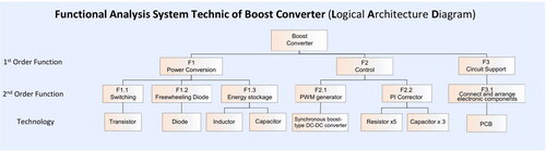
Following the FAST analysis, the PE designer constructed the logical architecture diagram of the converter, as depicted in . The primary order functions of a boost converter were discretized into three functions: power conversion, control, and circuit connection. These functions were further decomposed into second-order functions. As the second-order functions cover the basic functionalities of the converter system, the PE designer selected suitable technologies for each second-order function and sized them accordingly to meet the electrical requirements.
Figure 8. FAST analysis of the boost converter.
4.2.2. Step 2: Construction of a hardware eco-design database
After calculating the electrical constraints associated with the technologies, the boost converter designer proceeded to select hardware components from catalogues. Apart from considering technical parameters and economic costs, the methodology required the PE designer to construct a hardware ecodesign dataset that incorporates circularity and environmental parameters within the hardware block. In this case study, the Mosfet FDS5680 was chosen as the transistor. describes the technical, circularity and environmental parameters, associated with the Mosfet, and its economic value. Then the LCA software EIME was used to specify the corresponding Life Cycle Inventory (LCI) of the hardware blocks. The CODDE® database (version: CODDE-2022-09) provides a ‘transistor’ system unit, described as a small outline transistor, low power, compatible with the Mosfet technical specification described in . The corresponding mass of 0.224 g was specified accordingly by the PEC designer, as well as the type and number of soldering points required to assembly this Mosfet.
Table 5. Example of hardware ecodesign database content (block definition diagram).
At this step, clarifying the value of the technical parameters targeted by the hardware supported the PE designer in objectively simulating the technical performance associated to a function. For instance, in the case of the switching function, junction temperature, conduction and switching losses were calculated to validate the hardware choice from a technical standpoint.
4.2.3. Step 3: Integrated life cycle assessment
Life Cycle Analysis (LCA) is a standardized and mature systems-oriented analytical method that provides a life cycle perspective for quantitatively assessing the potential environmental impacts of products or services. The ISO based standards 14040:2006 and 14044:2006 offer general guidance for performing LCAs (ISO 14040, 14040, Citation2006; ISO 14044, 2006). PE industry is part of a ‘high tech’ industrial system that involves complex industrial systems, from raw extraction to the end of life treatments. LCA can help to analyze the systemic environmental impacts generated by his design choices, by embracing the complexity of the whole value chain. In a simplistic vision, the LCA 14040:2006 ISO standard-based method consists of defining the goal and scope, conducting inventory analysis, performing impact assessment, and interpreting results.
The objectives of performing a LCA in this case study were to inform PEC designers of the environmental consequences of their design choices to build the boost converter, visualize the heterogeneity of environmental impacts generated by the design solutions chosen by the designer to answer the converter’s functions, identify hotspots, and compare different design scenarios based on the integration of heterogeneous constraints.
The functional unit of the boost converter is to convert the input voltage from 12 V to 24 V output with an output power of 20 W for a speaker amplifier in hybrid vehicles, according to the reference usage scenario (5 hours per week) and during a Reference Service Life (RSL) of 15 years. Each phase of the life cycle of the boost converter, including raw materials extraction, manufacturing, distribution, use and disposal, is included in the system boundaries (cf. Appendix B). As no specific data are available for distribution stage, the default data defined in the Product Category Rules for Electrical and Electronic product are taken into consideration for all the stages (PEP ecopassport®, 2021), from manufacturing to end-of-life: International transport: 19,000 km by boat plus 1,000 km by lorry; intracontinental transport: 3,500 km by lorry; Local/domestic transport: 1,000 km by lorry. The LCA software EIME version 6 has been used to carry out the inventory and subsequently apply the life cycle impact methodology. For the impact calculation stage, the indicator set ‘PEF/EN15804 + A2’ available in EIME was used, which respond to the recommendations of the Technical Committee of the Type III environmental declaration program, entitled PEP Ecopassport® (PEP Ecopassport, Citation2021).
During the LCI stage, the inventory data for the manufacturing step was mainly extracted from the ecodesign database constructed at the Step 2. Subcomponent input flows have been structured and modeled according to the logical architecture established through the BDD. This modeling method links environmental impact flows with the different functions, keeping the denomination coherency for ensuring the interoperability between software.
A heatmap, illustrated in , was used to facilitate the tracking of hotspots and communicate the results with other project members in accordance with LCA results visualization recommendations (Rio et al., Citation2020). This approach allowed, for such a case of multisystem-level environmental impact analysis, the PE designer to understand the manufacturing environmental consequences (column) of his design choices associated with each function (row). By identifying functions that generated the highest negative impacts across various impact indicator categories, priority areas for design revision could be easily identified. During the second design choice iteration the PE designer selected an alternative freewheeling diode component, and several impact transfers between indicators occurred, leading to the redistribution of impacts among the second-order functions. The designer found useful to compile multiple heatmaps for his different design scenarios to take his final design decision-making.
Figure 9. Heat map representation of manufacturing environmental impact tracking in converter’s functional structure.

4.2.4. Step 4: Inducing design change
The previous step supported the PE designer in improving the boost converter design by (1) incremental ecodesign or (2) radical innovation, by identifying areas where the environmental performances of the components chosen and associated electronic processes cause the most damages.
Following the option (1), the PE designer proactively explored alternative hardware options for functions identified as hotspots. For instance, the freewheeling diode was recognized as a hotspot in terms of its impact on the climate change indicator (kg CO2-eq). Consequently, the designer considered alternative diode choices to mitigate the environmental consequences associated with this function. Following the option (2), the PE designer envisaged creating two PCB Assemblies (PCBA): PCBA1 (integrating the components for power conversion), and PCBA2 (incorporating the components of control, including the integrated circuit). This modular design approach initiated by the PE designer in this case study appeared to be particularly environmentally beneficial due to the higher risk of failure associated with the power conversion part, attributed to the relatively low reliability of the transistor. By adopting this approach, the control part has the potential to be reused after its first usage, resulting in improved overall environmental impacts on the system. This is particularly beneficial in terms of resource use and reducing pollution to the air, water, and soil, which would otherwise occur through waste landfill or incineration processes straight after being used only once.
4.2.5. Step 5: Performance evaluation and comparison of design scenarios
The prospective LCA can be used to estimate the potential; environmental impacts of the ecodesign scenario. The option (1) incremental ecodesign is chosen to illustrate the step 5. The adoption of new hardware and life cycle model resulted in changes to the system’s technical parameters, which in turn had an impact on its technical, environmental, and economic performances. Between steps 4 and 5, multiple iterations occurred until the ‘optimal’ design solution had been selected by the designer. He considered environmental, economic, and socio-technical aspects (including more personal values linked to his own motivation to reuse components and being able to repair the boost in a few years if required) as a compromise. The proposed performance evaluation platform provided to the PE designer a spider chart to monitor the boost performance evolution over the design iterations, when (re-)organizing topology and (re-)selecting hardware components. An illustration is given , comparing the two design scenarios performances obtained by the designer. In order to enhance the technical performance of the freewheeling diode, the PE designer replaced the reference diode (VB30100S) with another option (VS-10BQ060). In this case, the PE designer found useful to compare on the same radar charts the two design options he ended up with, based on a multiple performance analysis (established on five environmental impact indicators, four technical indicators and cost). The trade-off between potential technical and environmental impacts and costs was facilitated. The complete data of this hardware block can be found in Appendix C.
Figure 10. Example of systematic evaluation of design changes during PDP iterations.
4.4. Limitations and future development
As an answer to the functional requirements for supporting ecodesign of PCB-based PEC (described in Section 3.5), the proposed FB-LCA model presented in this paper aims to address the functional requirement 1: support the definition of functional structure and optimization of technical solutions by considering multiple environmental impacts indicators generated all along its lifecycle (from manufacturing, transport, use, repair, to end-of-life). The proposed ecodesign application five-step method aims to address the functional requirement 5: support an operational ecodesign implementation in the PDP.
The case study of the boost converter is a first attempt to measure the effectiveness of the FB-LCA model in coupling environmental impacts indicators with the functional structure of the PEC through LAD, thereby identifying environmental hotspots across functional blocks. The Life Cycle Inventory (LCI) foreground parameters specified in the BDD supported the exploration of ecodesign spaces across functional blocks and the development of ecodesign scenarios for optimizing technical solutions. The integration of environmental profile and circularity profile into the BDD enabled, address environmental aspects as a performance of functions provided by PEC, in conjunction with technical and economic performances.
The limitation of this case study relies on three aspects.
Firstly, the case study is limited to the illustration of a technology optimization. The performance of the FB-LCA model in supporting functional innovation and system innovation (Design for circularity) is not demonstrated in this case study. The chosen boost converter represents the basic power converter, consisting only of the necessary functional blocks for power conversion. This simplicity does not reflect the complexity of the majority of industrial products, but illustrate an integrated ecodesign reasoning being a simple and common PE based product design development process. The ecodesign scenario implemented in this case study focuses on optimizing technical blocks. While a modular design option was proposed to facilitate converter repairs and extend its lifetime, it was not implemented due to limited development time. This first encouraging results motivate in future research a case study involving a more complex PEC in an industrial context to test and evaluate the effectiveness of the FB-LCA model in supporting functional innovation and system innovation (Design for circularity).
Secondly, the case study lacks of some trade-off analysis. The case study focuses on reducing environmental impacts in the manufacturing stage. The heatmap is ‘only’ showing the distribution of multiple manufacturing environmental impact indicators among functional blocks, and not addressing an in-depth analysis to evaluate the potential environmental gains and losses across different lifecycle stages, especially in the use stage and for circularity scenarios such as the repair stage. An in-depth analysis would explore additional questions, such as which secondary effects in manufacturing, repair, and end-of-life would be caused by an ecodesign scenario optimizing energy efficiency? What will be the secondary effects in use, repair, and end-of-life caused by adopting the ecodesign scenario reducing the manufacturing impacts of electronic components? This deeper analysis opens to ongoing research developments of an ecodesign space and a secondary effects analysis model (Functional requirement 4), as well as a design parameter’s sensitivity analysis model (Functional requirement 2). In this perspective, the goal is to quantitatively analyze and visualize the potential trade-offs with the relevant indicators before any ecodesign implementations.
Thirdly, this boost converter case study only considers circularity at the component level, as exemplified in the BDD of the technical block. The PCB design’s compatibility with circularity scenarios is not addressed. Design constraints aimed at facilitating operations in repair, reuse, and remanufacturing need to be considered in the PCB design. For instance, the addition of test points to facilitate diagnostics and preserving accessible space for desoldering iron are required. The PCB design’s compatibility with circularity scenarios is also addressed as a (Functional requirement 3).
5. Conclusion and perspective
Despite the latest ecodesign methods proposed by researchers to assist Power Electronic industry Product Developments, as well as the regulation incentives to move toward circular economy, circularity and environmental constraints are still not well integrated together into PE Converter Product Development Processes (PEC-PDP). Ten semi-structured interviews results with PE designers were therefore exploited in this research to identify the remaining barriers preventing the ecodesign integration in this specific industrial field. The specific contextual factors involved in the design process of PCB-based PEC identified as crucial include the key actors and their skills, the design activities conducted, some specific design criteria conditioning environmental impact generations and circularity options, the design methods and tools used by PE designers, as well as the product design information development supports, including ecodesign software databases. These factors were categorized into three main stages: conversion structure design, hardware selections, and PCB design. The field investigation revealed a methodological requirement for an ecodesign support process, integrated into the PCB-based PEC PDP specific ecodesign working and decision-making steps ().
As an answer to effectively implement ecodesign in PCB-based PEC PDP enabling functional innovation and system innovation, this paper proposed a parameterized Functional Block-based Life Cycle Analysis (FB-LCA) model. The FB-LCA model captures the Life Cycle Inventory (LCI) based on functional structures, integrating circularity scenarios into the lifecycle modelling ().
The proposition points out the limitations found in existing LCA models, which primarily rely on component inventory and adopt a linear lifecycle perspective. By contrast, the proposed FB-LCA aims to assist designers in defining the functional structures and optimizing the technical solutions by assessing the product performance through several environmental impacts indicators and across its entire (potential) lifecycle (from manufacturing and transportation to use, circularity considerations, and end-of-life scenarios).
The article lastly developed a five-step methodology to operationalize the implementation of the FB-LCA model. A case study of a PCB-based boost converter was conducted in collaboration with a PE engineer to test the practical implementation of FB-LCA model. The results of the case study demonstrate the effectiveness of the FB-LCA model in identifying the environmental hotspots across functional blocks, exploring ecodesign spaces among parameters and developing of ecodesign scenarios. However, this simplistic case study remains indeed limited to the boost converter context, size and level of complexity. This case did not explore functional innovation choices, complex trade-off analysis situations, and was limited to circularity issues addressed at a component level (the boost converter components).
Ongoing research perspectives include a more complex PEC-PDP implementation case study in an industrial context. Following a similar case study protocol, this additional research proposition test is necessary to evaluate the effectiveness of the FB-LCA model in supporting functional innovation and system innovation (Design for circularity) in a more complex product. LCA model for other circularity scenario, i.e. reuse, remanufacturing, repurposing, needs to be developed as well. The index to evaluate design compatibility to circularity is planned to be developed and tested with divers PEC products in the coming months.
In future research, to achieve absolute environmental sustainability for PEC, transitioning from 'better’ to 'good enough’, there should be a focus on developing methodologies for defining limits for environmental impact indicators. This would be necessary to ensure the PEC fraction of the electronic-based industrial world to remain within planetary boundaries in the coming decade (Persson et al., Citation2022). In addition to environmental considerations, achieving alignment with sustainability objectives necessitates a thorough examination of the social impacts across the entire life cycle of PECs, using methodologies such as Social Life Cycle Analysis (SLCA) to ensure comprehensive sustainability integration (Jørgensen et al., Citation2008).
Ethical approval
Regarding ethical approval, the Ethical Committee for Research of Univ. Grenoble Alpes (CERGA), accredited by the US Office for Human Research Protection (OHRP) as an Institutional Review Board (IRB), indicated that ethical approval was not required for this study, as this study consists of non-interventional surveys and has no impact on human participants.
CRediT authorship contribution statement
Li Fang: Conceptualization, Methodology, Validation, Formal analysis, Investigation, Data curation, Writing original draft, Writing - review & editing, Visualization. Pierre Lefranc: Methodology, Resources, Review & editing, Visualization, Supervision, Project administration, Funding acquisition. Maud Rio: Methodology, Resources, Review & editing, Visualization, Supervision, Project administration, Funding acquisition.
| Nomenclature | ||
| AC | = | Alternative Current |
| AM | = | Assembly Module |
| CEAP | = | Circular Economy Action Plan |
| DC | = | Direct Current |
| DRM | = | Design Research Methodology |
| EEE | = | Electrical and Electronic Equipment |
| LCA | = | Life Cycle Analysis |
| PCB | = | Printed Circuit Board |
| PCBA | = | Printed Circuit Board Assembly |
| PDP | = | Product Development Process |
| PE | = | Power Electronics |
| PEC | = | Power Electronics Converters |
| RC | = | Research Clarification |
| RoHS | = | Restriction of Hazardous Substances Directive 2022/95/EC |
| REACH | = | Registration, Evaluation, Authorisation and Restriction of Chemicals (EC) No 1907/2006 |
| SWOT | = | Strength, Weakness, Opportunity, Threat analysis |
| TO | = | Technological Organigram |
| WEEE | = | Waste from Electrical and Electronic Equipment |
Supplementary Material.docx
Download MS Word (90.2 KB)Data availability statement
The authors confirm that the data supporting the findings of this study are available within the article and its supplementary materials. The corresponding author, Li Fang, agree to share the data upon reasonable request.
Disclosure statement
No potential conflict of interest was reported by the author(s).
Additional information
Funding
Notes on contributors
Li Fang
Li Fangis a PhD candidate at the Polytechnic Institute of Grenoble, affiliated with both the G-SCOP Laboratory and the G2ELab Laboratory in France. Her doctoral research is a part of the ANR VIVAE project (Innovative Lifecycle to Keep Value in Power Electronics). Her research work focuses on the integration of ecodesign in the sustainable product development process, emphasizing environmental impact modeling, control, and monitoring from a circular economy perspective.
Pierre Lefranc
Pierre Lefranc received the M.S. degree in electrical engineering from Supelec, Paris, France, in 2002. He received the Ph.D. degree in electrical engineering from the Institut National de Sciences Appliquees de Lyon, Villeurbanne, France, in 2005. He was an Assistant Professor in the Energy Department, Supelec Engineering School, France, from 2006 to 2012. He is currently with the ENSE3 Engineering School, INP Grenoble, G2ELAB Laboratory, Grenoble, France, as an Associate Professor. His research interests include modeling, optimization, design of power electronic applications, and gate drive for semiconductor devices. Since 2021, he is working on eco-design methodologies and considering environmental impacts of power electronics technologies.
Maud Rio
Maud Riois an Associate Professor at Grenoble Alps University G-SCOP Laboratory, part of the CoSYS Team. She completed her Ph.D. in 2012 after graduating in mechanical design engineering and sustainable development in 2009 from the UTT (France). Her research includes developing models and designing methods based on the approach of integrated design to boost the environmental performance of products and processes in line with emerging technologies, leading to new forms of consumption and production. She is actively involved in European research projects and national research projects, in the field of design for sustainable circularity, and co-supervises PhD students. Being involved in researcher communities in sustainability, she co-founded the Technical Comity “Sustainability” in the scientific communities SAGIP and GDR MACS. In charge of planning, developing and supporting the sustainability and ecodesign teaching at the mechanical and manufacturing department of the IUT1 of Grenoble, she also drives research projects in the field of integrating absolute sustainability thinking into academia.
References
- A New Circular Economy Action Plan For a Cleaner and More Competitive Europe. (2020). https://eur-lex.europa.eu/legal-content/EN/TXT/?qid=1583933814386&uri=COM:2020:98:FIN
- Bauer, T., Mandil, G., Naveaux, É., & Zwolinski, P. (2016). Lifespan extension for environmental benefits: A new concept of products with several distinct usage phases. Procedia CIRP, 47, 430–435. https://doi.org/10.1016/j.procir.2016.03.079
- Blessing, L. T. M., & Chakrabarti, A. (2009). DRM, a design research methodology. London: Springer. https://doi.org/10.1007/978-1-84882-587-1
- Borres, B. A., Lorenz Ardiente, I., Satur, J. R., Valiente, F., & Martinez, J. (2019 Design optimization of a two-phase interleaved transition mode boost converter for power factor correction [Paper presentation]. 2019 IEEE 11th International Conference on Humanoid, Nanotechnology, Information Technology, Communication and Control, Environment, and Management (HNICEM) (pp. 1–6). https://doi.org/10.1109/HNICEM48295.2019.9072711
- Bovea, M. D., & Pérez-Belis, V. (2012). A taxonomy of ecodesign tools for integrating environmental requirements into the product design process. Journal of Cleaner Production, 20(1), 61–71. https://doi.org/10.1016/j.jclepro.2011.07.012
- Bracquene, E., Peeters, J. R., Burez, J., De Schepper, K., Duflou, J. R., & Dewulf, W. (2019). Repairability evaluation for energy related products. Procedia CIRP, 80, 536–541. https://doi.org/10.1016/j.procir.2019.01.069
- Brambila-Macias, S. A., & Sakao, T. (2021). Effective ecodesign implementation with the support of a lifecycle engineer. Journal of Cleaner Production, 279, 123520. https://doi.org/10.1016/j.jclepro.2020.123520
- Dangal, S., Faludi, J., & Balkenende, R. (2022). Design aspects in repairability scoring systems: comparing their objectivity and completeness. Sustainability, 14(14), 8634. https://doi.org/10.3390/su14148634
- de Freitas Lima, G., Rahmani, B., Rio, M., Lembeye, Y., & Crebier, J.-C. (2021). Eco-dimensioning approach for planar transformer in a dual active bridge (DAB) application. Eng, 2(4), 544–561. https://doi.org/10.3390/eng2040035
- Debusschere, V., Ben Ahmed, H., & Multon, B. (2007). Eco-design of electromagnetic energy converters: The case of the electrical transformer. In IEEE IEMDC 2007 (pp. 1599–1604). https://hal.archives-ouvertes.fr/hal-00676233
- Diaz, A., Schöggl, J.-P., Reyes, T., & Baumgartner, R. J. (2021). Sustainable product development in a circular economy: Implications for products, actors, decision-making support and lifecycle information management. Sustainable Production and Consumption, 26, 1031–1045. https://doi.org/10.1016/j.spc.2020.12.044
- Directive 2009/125/EC of the European Parliament and of the Council. (2009). of 21 October 2009 Establishing a Framework for the Setting of Ecodesign Requirements for Energy-Related Products (Text with EEA Relevance), CONSIL, EP, 285 OJ L http://data.europa.eu/eli/dir/2009/125/oj/eng
- Directorate-General for Environment. (2022). Proposal for ecodesign for sustainable products regulation. https://environment.ec.europa.eu/publications/proposal-ecodesign-sustainable-products-regulation_en
- Falck, J., Felgemacher, C., Rojko, A., Liserre, M., & Zacharias, P. (2018). Reliability of power electronic systems: An industry perspective. IEEE Industrial Electronics Magazine, 12(2), 24–35. https://doi.org/10.1109/MIE.2018.2825481
- Fang, L., Lefranc, P., & Rio, M. (2023). Barriers for eco-designing circular Power Electronics Converters. Procedia CIRP, 116, 287–292. https://doi.org/10.1016/j.procir.2023.02.049
- Fang, L., Romano, T. T., Alix, T., Crebier, J.-C., Lefranc, P., Rio, M., & Zwolinski, P. (2023, March 22). Eco-design implementation in power electronics: A literature review. In International Symposium on Advances Technologies in Electrical Systems (SATES 23). https://hal.science/hal-04074109
- Flipsen, B., Huisken, M., Opsomer, T., & Depypere, M. (2019). Smartphone reparability scoring: PLATE 2019. PLATE 2019
- Forti, V., Baldé, C. P., Kuehr, R., & Bel, G. (2020). The global e-waste monitor 2020, 120.
- Holt, J., & Perry, S. (2008). SysML for systems engineering (1. publ). Institution of Engineering and Technology. London.
- IEC 62430. (2019). IEC 62430:2019. ISO. https://www.iso.org/standard/79064.html
- ISO 14040. (2006). ISO 14040:2006. ISO. https://www.iso.org/cms/render/live/fr/sites/isoorg/contents/data/standard/03/74/37456.html
- ISO 14044:2006. (2006). ISO. https://www.iso.org/cms/render/live/fr/sites/isoorg/contents/data/standard/03/84/38498.html
- Jaouen, C., Multon, B., & Barruel, F. (2011). Design optimization methodology for power converters based on global energy requirement criteria. Application to a DC-DC flyback structure. In Proceedings of the 2011 14th European Conference on Power Electronics and Applications (pp. 1––10).
- Javier Hurtado Albir, F., & Antonio Carrasco Hernández, J. (2011). Environmental aspects of manufacturing and disposal of power electronics equipment. EPE Journal, 21(3), 5–13. https://doi.org/10.1080/09398368.2011.11463798
- Johansson, G. (2002). Success factors for integration of ecodesign in product development: A review of state of the art. Environmental Management and Health, 13(1), 98–107. https://doi.org/10.1108/09566160210417868
- Jørgensen, A., Le Bocq, A., Nazarkina, L., & Hauschild, M. (2008). Methodologies for social life cycle assessment. The International Journal of Life Cycle Assessment, 13(2), 96–103. https://doi.org/10.1065/lca2007.11.367
- Kampen, D., & Burger, M. (2016). Drive system loss reduction by allpole sine filters. PCIM Europe 2016; International Exhibition and Conference for Power Electronics, Intelligent Motion, Renewable Energy and Energy Management (pp. 1–4).
- Kim, J.-W., Noh, Y.-S., Joo, D., Hwang, D. Y., Kim, J.-H., & Choi, J.-H. (2021). Development of high efficiency and power density converter using SiC MOSFET for xEV [Paper presentation]. 2021 24th International Conference on Electrical Machines and Systems (ICEMS) (pp. 2132–2137). https://doi.org/10.23919/ICEMS52562.2021.9634326
- Middendorf, A., Benecke, S., Nissen, N. F., Wittler, O., & Lang, K.-D. (2015). Establishing ecoreliability of electronic devices in manufacturing environments. Procedia CIRP, 26, 436–442. https://doi.org/10.1016/j.procir.2014.07.063
- Millet, D. (2003). Environmental integration in design. Paris: Hermes Science publications.
- Multon, B., Ben Hamed, H., Debusshere, V., Aubry, J., Jaouen, C., & Barruel, F. (2012a). Expériences de recherche en éco-conception dans le domaine du génie électrique. European Journal of Electrical Engineering, 15(5), 433–449. https://doi.org/10.3166/ejee.15.433-449
- Multon, B., Ben Hamed, H., Debusshere, V., Aubry, J., Jaouen, C., & Barruel, F. (2012b). Research experiences in ecodesign in the field of Electrical Engineering. European Journal of Electrical Engineering, 15(5), 433–449. https://doi.org/10.3166/ejee.15.433-449
- Pahl, G., & Beitz, W. (1996). Engineering Design. K. Wallace (Ed.). London: Springer. https://doi.org/10.1007/978-1-4471-3581-4
- PEP Ecopassport. (2021). PEP Ecopassport. http://www.pep-ecopassport.org/
- PEP ecopassport®. (2021). Product category rules for electrical, electronic and HVAC-R products, PEP ecopassport® PROGRAM.
- Persson, L., Carney Almroth, B. M., Collins, C. D., Cornell, S., de Wit, C. A., Diamond, M. L., Fantke, P., Hassellöv, M., MacLeod, M., Ryberg, M. W., Søgaard Jørgensen, P., Villarrubia-Gómez, P., Wang, Z., & Hauschild, M. Z. (2022). Outside the safe operating space of the planetary boundary for novel entities. Environmental Science & Technology, 56(3), 1510–1521. https://doi.org/10.1021/acs.est.1c04158
- Pirson, T., Delhaye, T. P., Pip, A. G., Le Brun, G., Raskin, J.-P., & Bol, D. (2023). The environmental footprint of IC production: Review, analysis, and lessons from historical trends. IEEE Transactions on Semiconductor Manufacturing, 36(1), 56–67. https://doi.org/10.1109/TSM.2022.3228311
- Popescu, R., Botez, G., Mihai, C., & Stoia, D. (2017 A comparative study of transformers losses with eco-design requirements [Paper presentation]. 2017 International Conference on Optimization of Electrical and Electronic Equipment (OPTIM) & 2017 Intl Aegean Conference on Electrical Machines and Power Electronics (ACEMP) (pp. 25–30). https://doi.org/10.1109/OPTIM.2017.7974942
- Popović-Gerber, J., Ferreira, J. A., & Wyk, J. D. v (2011). Quantifying the value of power electronics in sustainable electrical energy systems. IEEE Transactions on Power Electronics, 26(12), 3534–3544. https://doi.org/10.1109/TPEL.2011.2166088
- Popović-Gerber, J., Oliver, J. A., Cordero, N., Harder, T., Cobos, J. A., Hayes, M., O'Mathuna, S. C., & Prem, E. (2012). Power electronics enabling efficient energy usage: Energy savings potential and technological challenges. IEEE Transactions on Power Electronics, 27(5), 2338–2353. https://doi.org/10.1109/TPEL.2011.2171195
- Potting, J., Hekkert, M. P., Worrell, E., & Hanemaaijer, A. (2017). Circular economy: Measuring innovation in the product chain. Planbureau Voor de Leefomgeving, PBL publication number: 2544, 9–14.
- Rahmani, B., Lembeye, Y., Rio, M., & Crebier, J.-C. (2021). Analysis of passive power components reuse. PCIM Europe Digital Days (International Exhibition and Conference for Power Electronics, Intelligent Motion, Renewable Energy and Energy Management Proceedings) (pp. 956–963). https://hal.archives-ouvertes.fr/hal-03347175
- Rio, M., Blondin, F., & Zwolinski, P. (2019). Investigating product designer LCA preferred logics and visualisations. Procedia CIRP, 84, 191–196. https://doi.org/10.1016/j.procir.2019.04.293
- Rio, M., Blondin, F., Coeurdevey, J., & Pochat, S. L. (2020). pLayRoOM-LcA Results chOice Maker: Représentation partagée d’Analyse du Cycle de Vie.
- Rio, M., Khannoussi, K., Crebier, J.-C., & Lembeye, Y. (2020). Addressing circularity to product designers: Application to a multi-cell power electronics converter. Procedia CIRP, 91, 134–139. https://doi.org/10.1016/j.procir.2020.02.158
- Romano, T. T., Alix, T., Lembeye, Y., Perry Lembeye, N., & Crebier Lembeye, J. C. (2023). Towards circular power electronics in the perspective of modularity. Procedia CIRP, 116, 588–593. https://doi.org/10.1016/j.procir.2023.02.099
- Sanfelix, J., Cordella, M., & Alfieri, F. (2019). Methods for the assessment of the reparability and upgradability of energy-related products—Publications Office of the EU. https://op.europa.eu/fr/publication-detail/-/publication/c0b344f5-216c-11ea-95ab-01aa75ed71a1/language-en
- Spreafico, C., Landi, D., & Russo, D. (2023). A new method of patent analysis to support prospective life cycle assessment of eco-design solutions. Sustainable Production and Consumption, 38, 241–251. https://doi.org/10.1016/j.spc.2023.04.006