Abstract
Large-scale fabrication of graphene and reduced graphene oxide (rGO) is important for industrial and research applications of this material. Chemical solution methods offer a low-cost alternate to produce rGO with high yield. This research is to explore the effect of chemical and thermal reduction on the quality of chemically synthesized graphene and its derivatives. A top-down process involved the chemical oxidation of the precursor graphite powder (size ~10 μm) using a concentrated mixture of sulphuric acid and nitric acid. Oxidized graphite powder was thermally exfoliated at 1,050°C for 30 s to produce graphene oxide (GO). Chemical reduction in GO sheets with sodium borohydride led to the formation of rGO. Characterization by Raman spectroscopy revealed an intensity ratio of 2D/G bands of rGO as approximately 0.5 indicating a multi-layered structure. X-ray diffraction, field emission scanning electron microscopy (FESEM) and atomic force microscopy (AFM) results indicated a multi-layered rGO with a lateral size up to 5 μm.
Public Interest Statement
Large scale production yet maintaining quality has been an engrossing area of research in the production of graphene derivatives globally since 2004. Due to their simplicity and lower cost, wet chemical methods result in lower-cost alternative to produce reduced graphene oxide (rGO) with higher yield. The present research is an effort to synthesize rGO through an improved chemical route and quality analysis of the product by appropriate techniques. Rapid thermal treatment combined with chemical reduction step improved the exfoliation and isolation of rGO nanoplatelets.
1. Introduction
Graphene is a monoatomic thick (~0.35 nm) sheet consisting of carbon atoms arranged in a honeycomb-like (hexagonal) structure. High electrical conductivity, large specific surface area and excellent charge mobility are the main characteristics that make graphene-based materials excellent candidates for a wide variety of electrical applications (Pinto, Jones, Goss, & Briddon, Citation2010). A charge carrier mobility up to 3,700 cm2/Vs (Liao & Duan, Citation2010), ability to withstand current density of 108 A/cm² (Lin, et al., Citation2013), transmittance up to 97% to the visible light (Mkhoyan et al., Citation2009) and high thermal conductivity of the order of 5 × 10³ W/mK (Balandin et al., Citation2008) has made graphene and its derivatives among the hot topics of research today.
GO and rGO are intriguing materials for photonics and electronic devices both for intrinsic characteristics and as precursors for the synthesis of graphene. Overall, a fine control of the chemical and physical properties is required since the performances of graphene-based systems depend on the reduction state of graphene oxide that is strongly affected by processing. Since its first isolation (Park & Ruoff, Citation2009), graphene has witnessed a surge of interest to develop methods for a larger-scale and economical production. Chemical solution methods have been popular because of the inexpensive starting materials and the requirement of simple processing equipment. Methods proposed by Staudenmaier, Hofmann and Hummers remained more prominent (Poh et al., Citation2012) to synthesize graphene by chemical oxidation of graphite and subsequent reduction.
In order to facilitate separation of the individual graphene layers, the van der Waals attraction between graphite basal planes has to be overcome, for which thermal or chemical exfoliation has been proposed (Stankovich et al., Citation2007). One approach is to expand the interlayer distance by oxidation of graphite and intercalation of compounds (Ang, et al., Citation2009). The resulting oxidized graphite revealed a disordered graphitic stacking with d-spacing increased from ~0.34 to 0.7 nm (Ang et al., Citation2009). Exfoliation by ultrasonication and thermal treatments increases the pressure between adjacent layers of GO due to gases/vapours released from decomposition reactions (Hernandez et al., Citation2008; Schniepp et al., Citation2006).
It is desired to study the effect of chemical oxidation and thermal exfoliation on the quality and size of graphene. The present research aims to process graphite through a facile chemical method to produce rGO. To achieve the exfoliation of graphene, a thermal treatment step was integrated. Detailed characterization by XRD, Raman spectroscopy, FESEM and AFM was conducted to study the product properties at subsequent stages.
2. Results and discussion
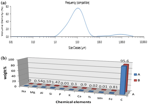
The particle size of the precursor graphite is an important parameter in the chemical oxidation reactions. If the size is too smaller, rapid reaction rate will be observed while the end product lateral dimension reduces and vice versa. An optimum size is therefore necessary to obtain an appreciable size of the graphene sheets after exfoliation and chemical reduction. The particle size results obtained from the as-received graphite powder exhibited a size in the range 1–30 μm as shown in Figure (a). The median of normal distribution at 10 μm indicates the average particle diameter in the sample. The chemical composition by XRF obtained from the same sample is shown in Figure (b). The sample consisted of carbon as the main constituents with minor inclusions of Si, Ca and Fe.
The microstructure of the precursor graphite particles before and after chemical processing as observed by FESEM is shown in Figure . The as-received graphite powder revealed an irregular flaky shape, which is the typical morphology of the graphite powder. The corresponding EDX analysis is shown in Figure (b) that indicates the carbon peak only from the starting graphite powder. The quantitative analysis indicated up to 98% carbon in the precursor graphite which is in good agreement with the XRF results. The results suggest that the commercial grade graphite powder contained impurities which may increase the processing time to remove them without affecting the quality of graphene.
Figure 2. FEG-SEM images of the precursor graphite powder (a), corresponding EDX analysis (b), oxidized (c), chemically reduced (d) and thermally exfoliated (e) products, 5 μm scale bar (a, b and e) and 10 μm scale bar (c and d).
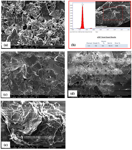
Figure (c) shows the microstructure of graphite after the chemical oxidation reaction. The plates of thin graphite oxide are visible with a regular morphology with size approximately equal to the original size of graphite particles. However, reducing the size of parent graphite flake size will not make a significant difference in GO flake size but it will increase the oxidation reaction (McAllister et al., Citation2007). After the chemical reduction step, the microstructure of rGO is shown in Figure (d). The variations in particle size of rGO in the image may be attributed to poor dispersion during centrifugation and SEM sampling. On the other hand, microstructure of the thermally exfoliated rGO is shown in Figure (e). A high -magnification image revealed the exfoliated individual thin graphene sheets after thermal reduction. By comparison with chemically treated rGO, the thermally reduced rGO looked more promising to obtain graphene with a relatively large aspect ratio.
Figure shows the Raman spectra obtained from the precursor graphite powder, GO and rGO samples synthesized by CHM and MHM, respectively. Various Raman active modes were observed in the sample by CHM corresponding to the in-plane and out of plane C-C bonding. The graphitic nature of the precursor powder was observed by a sharp band occurring near 1,592 cm−1 from sp2 carbon atoms denoted by G-band in Figure (a). After chemical oxidation, sharp bands appeared at 1,354, 1,640 and 2,750 cm−1. The prominent Raman signal at 1,354 cm−1 is attributed to the sp3 defects in the sp2 lattice, which is designated by the D-band and is related to the defects in graphene structure. Another peak at 2,750 cm−1 denoted by 2D-band is attributed to the development of graphene structure. In addition, results obtained from GO and rGO obtained by MHM are shown in Figure (b). The result for precursor graphite remains almost the same as discussed in Figure (a) earlier.
Figure 3. Raman Spectra of the as-received graphite powder, GO and rGO synthesized through (a) CHM and (b) MHM.
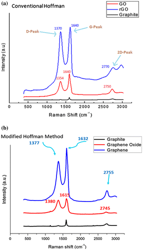
After chemical oxidation of the precursor graphite, more bands appeared at 1,380 cm−1 (D-band), 1,615 cm−1 (G-band) and 2,745 cm−1 (2D-band), respectively. Subsequent reduction by thermal exfoliation resulted in Raman bands appearing at 1,377 cm−1 (D-band), 1,632 cm−1 (G-band) and 2,755 cm−1 (D-band), respectively. Although both Raman spectra obtained from CHM and MHM samples looked similar in shape, the position and intensity of distinct Raman bands were changed after going through the oxidation and reduction processes. The specific Raman bands and their intensity ratios may provide useful information about the structure of graphene such as D/G band intensity ratio, which represents defects (edges, vacancies, ripples etc.) (Ferrari & Robertson, Citation2000) while 2D/G represents the number of layers in graphene (Shen & Lua, Citation2013). There is clear difference observed between shape and intensity of 2D peak of rGO and graphite. The Raman band intensity ratios obtained after chemical reduction and thermal exfoliation by CHM and MHM are listed in Table .
Table 1. Intensity ratio of (D/G) and (2D/G) bands in the product obtained from CHM and MHM
By comparison, a lower density of defects was observed for MHM than CHM on the basis of D/G intensity ratio. Moreover, graphene consisting of less number of layers was obtained by MHM compared to CHM by analysing the intensity ratios of 2D/G bands. It is inferred that lower stacking of graphene layers obtained in MHM may be the reason for lower number of defects and thus of better quality. However, the 2D/G intensity ratio of less than 1 in both methods suggests a multi-layered graphene structure.
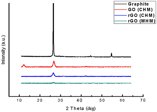
XRD patterns obtained from the precursor graphite, GO, rGO processed through CHM and MHM are given in Figure . The starting graphite powder produced a sharp peak at 26.54° 2θ angle. The corresponding d-spacing of this peaks was calculated to be 0.33 nm that precisely matched with the (002) plane of the graphite hexagonal structure. After chemical oxidation step, this main peak intensity was reduced and it transformed into a rather broad peak (GO CHM). An additional peak appeared at 12.35° angle with a corresponding d-spacing of 0.73 nm. This new peak is attributed to the graphite oxide structure formed after chemical oxidation of the precursor graphite and it is clearly in agreement with results shown by McAllister et al. (Citation2007).
Subsequent chemical reduction in GO by NaBH4 through CHM, the intensity of (002) carbon peak was further reduced while the GO peak was removed. This is attributed to the removal of functional oxide groups and exfoliation of graphene in multi-layered structure as indicated by Raman spectra earlier. Interestingly, the graphene produced by MHM revealed the lowest intensity of the (002) carbon peak in the XRD spectrum. It is inferred that the lowest intensity was due to the more effective separation of the individual graphene layers by the addition of thermal exfoliation step during processing.
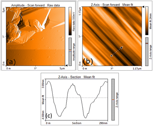
The AFM tapping mode images obtained from GO samples obtained through CHM are shown in Figure . The rGO sample prepared by CHM revealed graphene in the form of stacked layers as shown in Figure (a). A high-resolution AFM image shown in Figure (b) was obtained from a selected area of the image (indicated in Figure (a)). It shows the expanded graphene layers after chemical oxidation and thermal exfoliation. The gaps between individual layers are formed after entrapped in/out-of-plane functional groups decomposed and expelled as gases during the thermal reduction. The height profile image in Figure (c) was obtained from the area indicated by an arrow in Figure (b). Various tiny steps were successfully resolved by the AFM and corresponded to the distance between the two adjacent graphene layers i.e. 0.4–0.45 nm. It was slightly greater than the separation distance (0.33 nm) of individual graphene layers inside a perfect graphite crystal. It is attributed mainly to the intercalation of functional groups (oxides), and rapid thermal reduction which expanded the individual graphene layers.
3. Conclusions
A modified chemical solution method has been adopted to synthesize rGO and multi-layered graphene-based nanomaterials. Commercial grade, graphite precursor powder with defects was successfully oxidized and chemically reduced to yield GO and rGO. For high-quality rGO production, processing steps will be needed to remove defects from commercially available graphite. Thermal reduction was helpful to generate graphene structure in multilayers stacking with a better quality compared to the conventional method. The Raman spectra indicated that graphene was stacked in multilayer structure by comparing 2D/G band intensity ratio. XRD results suggested a successful conversion of precursor graphite into GO, rGO and graphene layers. Process optimization to produce separated graphene sheets through combined chemical and thermal exfoliation is proposed for further work.
4. Experimental
The raw materials and chemicals used in the fabrication of rGO included graphite powder, potassium chlorate, sodium borohydride, sulphuric acid, nitric acid, hydrochloric acid, hydrogen peroxide, diethyl ether and distilled water. All these were used in reagent grade purity except the graphite powder which was in commercial grade. A modified Hoffman method was adopted for the preparation of rGO and was compared with the conventional Hoffman method. A thermal reduction step was introduced to increase the exfoliation of GO by heating for short time at 1,050°C in air for 30 s.
4.1. rGO through the conventional Hoffman method (CHM)
The method used to prepare rGO by CHM is reported elsewhere (Poh et al., Citation2012). The reaction residue obtained after filtration and washing, with 5% HCl and de-ionized water, was ultrasonicated for 30 min, dried at 120°C for 24 h to obtain dried GO. This powder was chemically reduced with NaBH4 and dried in vacuum oven to obtain rGO.
4.2. rGO through a modified Hoffman method (MHM)
A similar procedure was followed as described above except that after washing with distilled water and 5% HCl, the mixture was subjected to thermal reduction for 30 s in the preheated furnace at 1,050°C. The powder was removed from furnace and cooled to room temperature and then washed with H2O2 and ether to remove further impurities. Chemical reduction was carried out with NaBH4 and product was dried in oven at 120°C to obtain rGO through MHM.
5. Characterization
The samples were characterized by employing various instruments at each stage. The electron microscopy was conducted by using FEI Nova 450 FESEM with EDX analyser. Powder XRD was conducted by using Phillips X’pert pro PMD operated at 40KV and 30 mA with Cu-Kα radiation scanned in the Braggs angle range of 20–80 degrees in continuous mode. Phase identification of the diffraction patterns was carried out by using the PAN analytical X-Pert high score. Raman spectroscopy was conducted at room temperature by using Horiba Jobin-Yvon T6400 with 514 nm excitation wavelength for 10 min. AFM imaging and analysis was conducted on a Nano surf Model in tapping mode. The sample for AFM was prepared by suspending the treated graphite particles in N, N-dimethylformamide (DMF) solution and ultrasonicated before spin-coating on clean glass slides at 2,000 rpm.
Funding
This work was funded by Ghulam Ishaq Khan Institute of Engineering Sciences and Technology.
Acknowledgment
We acknowledge the staff of FMCE, GIK institute for their help in experiments and characterization especially AFM imaging done by Dr Imran Khan. We also thank Prof Dr Arshad Saleem Bhatti and Dr Muhammad Anis-ur-Rehman at CIIT Islamabad for facilitating during Raman spectroscopy and XRD analysis.
Additional information
Notes on contributors
Qaiser Ali Khan
Qaiser Ali Khan is a master’s student in University of Kiel and Helmholtz-Zentrum Geesthacht Centre for Materials and Coastal Research, Germany. He passed his BSc degree in Materials science from GIK Institute, Pakistan with thesis supervision under Yasir Faheem Joya. His research interests are (1) Electrochemical behaviour of TiO2 layer and (2) synthesis and characterization of carbon nanomaterials.
References
- Ang, P. K., Wang, S., Bao, Q., Bao, Q., Thong, J. T., & Loh, K. P. (2009). High-throughput synthesis of graphene by intercalation−exfoliation of graphite oxide and study of ionic screening in graphene transistor. ACS Nano, 3, 3587–3594.10.1021/nn901111s
- Balandin, A. A., Ghosh, S., Bao, W., Calizo, I., Teweldebrhan, D., Miao, F., & Lau, C. N. (2008, March). Superior thermal conductivity of single-layer graphene. Nano Letters, 8, 902–907.10.1021/nl0731872
- Ferrari, A., & Robertson, J. (2000). Interpretation of Raman spectra of disordered and amorphous carbon. Physical Review B, 61, 14095–14107.10.1103/PhysRevB.61.14095
- Hernandez, Y., Nicolosi, V., Lotya, M., Blighe, F. M., Sun, Z., De, S., … Boland, J. J. (2008). High-yield production of graphene by liquid-phase exfoliation of graphite. Nature Nanotechnology, 3, 563–568.10.1038/nnano.2008.215
- Liao, L., & Duan, X. (2010, November). Graphene–dielectric integration for graphene transistors. Materials Science and Engineering: R: Reports, 70, 354–370.10.1016/j.mser.2010.07.003
- Lin, J., Peng, Z., Xiang, C., Ruan, G., Yan, Z., Natelson, D., & Tour, J. M. (2013, July). Graphene nanoribbon and nanostructured SnO 2 composite anodes for lithium ion batteries. ACS Nano, 7, 6001–6006.10.1021/nn4016899
- McAllister, M. J., Li, J., Adamson, D. H., Schniepp, H. C., Abdala, A. A., Liu, J., … Aksay, I. A. (2007). Single sheet functionalized graphene by oxidation and thermal expansion of graphite. Chemistry of Materials, 19, 4396–4404.10.1021/cm0630800
- Mkhoyan, K., Contryman, A. W., Silcox, J., Stewart, D. A., Eda, G., Mattevi, C., … Chhowalla, M. (2009, March). Atomic and electronic structure of graphene-oxide. Nano Letters, 9, 1058–1063.10.1021/nl8034256
- Park, S., & Ruoff, R. S. (2009, April). Chemical methods for the production of graphenes. Nature Nanotechnology, 4, 217–224.
- Pinto, H., Jones, R., Goss, J. P., & Briddon, P. R. (2010). Mechanisms of doping graphene. physica status solidi (a), 207, 2131–2136. https://doi.org/10.1002/pssa.201000009
- Poh, H. L., Šaněk, F., Ambrosi, A., Zhao, G., Sofer, Z., & Pumera, M. (2012). Graphenes prepared by Staudenmaier, Hofmann and Hummers methods with consequent thermal exfoliation exhibit very different electrochemical properties. Nanoscale, 4, 3515–3522. 10.1039/c2nr30490b
- Schniepp, H. C., Li, J. L., McAllister, M. J., Sai, H., Herrera-Alonso, M., Adamson, D. H., … Aksay, I. A. (2006). Functionalized single graphene sheets derived from splitting graphite oxide. The Journal of Physical Chemistry B, 110, 8535–8539.10.1021/jp060936f
- Shen, Y., & Lua, A. C. (2013). A facile method for the large-scale continuous synthesis of graphene sheets using a novel catalyst. Scientific Reports, 3, 1–6.
- Stankovich, S., Dikin, D. A., Piner, R. D., Kohlhaas, K. A., Kleinhammes, A., Jia, Y., … Ruoff, R. S. (2007). Synthesis of graphene-based nanosheets via chemical reduction of exfoliated graphite oxide. Carbon, 45, 1558–1565.10.1016/j.carbon.2007.02.034

