
Abstract
Objective: To evaluate fracture strength of veneered translucent zirconium dioxide crowns designed with different porcelain layer thicknesses.
Materials and Methods: Sixty crowns, divided into six groups of 10, were used in this study. Groups were divided according to different thicknesses of porcelain veneer on translucent zirconium dioxide cores of equal thickness (0.5 mm). Porcelain thicknesses were 2.5, 2.0, 1.0, 0.8, 0.5 and 0.3 mm. Crowns were artificially aged before loaded to fracture. Determination of fracture mode was performed using light microscope.
Results: Group 1.0 mm showed significantly (p ≤ .05) highest fracture loads (mean 1540 N) in comparison with groups 2.5, 2.0 and 0.3 mm (mean 851, 910 and 1202 N). There was no significant difference (p>.05) in fracture loads among groups 1.0, 0.8 and 0.5 mm (mean 1540, 1313 and 1286 N). There were significantly (p ≤ .05) more complete fractures in group 0.3 mm compared to all other groups which presented mainly cohesive fractures.
Conclusions: Translucent zirconium dioxide crowns can be veneered with minimal thickness layer of 0.5 mm porcelain without showing significantly reduced fracture strength compared to traditionally veneered (1.0–2.0 mm) crowns. Fracture strength of micro-veneered crowns with a layer of porcelain (0.3 mm) is lower than that of traditionally veneered crowns but still within range of what may be considered clinically sufficient. Porcelain layers of 2.0 mm or thicker should be used where expected loads are low only.
Introduction
Yttria-stabilized tetragonal zirconia polycrystal (Y-TZP), used as core material for all-ceramic dental restorations, is considered to be a reliable crown and bridge material for restoring patients’ oral functions, including esthetics [Citation1,Citation2]. The unique transformation toughening properties of Y-TZP give the material high mechanical strength and toughness which is one of the reasons that the material is often described as the ideal substitute for metal alloys for cores and frameworks in veneered restorations [Citation3,Citation4].
Despite the excellent mechanical properties of Y-TZP, superficial chip-off fractures in the veneering porcelain have been reported as a common issue and, furthermore, the most common reason for the clinical failure of veneered Y-TZP [Citation1,Citation5]. The mechanisms behind the chipping of veneered Y-TZP have been discussed in the literature. Studies have suggested various reasons, such as poor fracture toughness of the veneer materials [Citation6], inadequate bond strength between the veneer ceramic and the Y-TZP core [Citation7], inadequate core design in relation to veneer thickness [Citation8–10], mismatch of coefficients of thermal expansion between the veneer ceramic and the Y-TZP core [Citation7,Citation11], and finally problems relating to the build-up of residual stresses in the veneer material during firing due to improper cooling [Citation12,Citation13].
Several methods for preventing chip-off fracture of veneered Y-TZP restorations have been described in the literature, such as improving technical procedures [Citation14,Citation15] and creating different stress breaking designs [Citation8,Citation9,Citation16] in addition to producing materials with high standard processing and improved mechanical properties. A reliable way to avoid chip-off fractures is to fabricate monolithic restorations made entirely from translucent zirconium dioxide material with equivalent strength compared to traditional Y-TZP [Citation17]. However, this new direction away from bi-layered design toward monolithic restorations does not always completely eliminate the need to veneer translucent zirconium dioxide with porcelain to enhance the esthetic result when needed. By adding a thin layer of porcelain to translucent zirconium dioxide, it might be possible to improve the esthetic appearance of monolithic restorations [Citation18,Citation19]. This design, however, is not within the manufacturer’s recommendations and there is no recommendation as to how thin the porcelain layer can be made without affecting fracture strength of such micro-veneered translucent zirconium dioxide restorations.
According to manufacturer’s recommendations, the optimal thickness of veneering porcelain on a Y-TZP core should be 1.0–2.0 mm. In a mathematical analysis study, however, it was suggested that within a combination of two laminated materials, such as porcelain and Y-TZP, a reduced overall thickness of the combined materials lead to less detrimental stress formation in the porcelain after firing of the material [Citation12]. The results were confirmed in another finite element analysis (FEA) study where spherical specimens were used [Citation13]. Since the clinically weak point of veneered Y-TZP restorations is the porcelain layer [Citation6], the effect of reduced porcelain thickness might play a major role in fracture strength of the crowns. With that in mind, and to investigate if those findings are applicable on fracture strength of porcelain-veneered translucent zirconium dioxide crowns, a study evaluating the design of anatomically shaped crowns with minimum porcelain layer thicknesses is motivated. The preparation depth of the abutment should then be considered, since the overall thickness of a crown calls for a corresponding tooth preparation. Consequently, a thinner crown allows for a less aggressive tooth-preparation, which might have an impact on the prognosis of the tooth-crown complex [Citation20].
Therefore, the aim of this study was to investigate fracture strength of veneered translucent zirconium dioxide crowns designed with different porcelain layer thicknesses. The null hypothesis was that the veneer thickness does not affect fracture strength of veneered translucent zirconium dioxide crowns.
Materials and methods
Experimental design
A total of 60 standardized translucent zirconium dioxide crowns, divided into six groups of 10, were used in this study (). The six groups were divided according to different thicknesses of the porcelain layer on translucent zirconium dioxide cores of equal thickness (0.5 mm). The thicknesses of porcelain veneer were 2.5, 2.0, 1.0, 0.8, 0.5 and 0.3 mm. The gradual reduction in porcelain thicknesses, from group 2.5 to group 0.3, resulted in a corresponding decrease in preparation depths of the abutment dies without changing the outer dimensions of any of the crowns ().
Figure 1. An illustration showing the CAD files of the different groups with overall crown thicknesses (core/porcelain). All crowns had an equal core thickness but different porcelain thicknesses. The gradual reduction in crown thicknesses resulted in a corresponding decrease in preparation depths without changing the outer dimensions (the X-imaginary line) of any of the crowns. The red dotted line denotes the core/porcelain interface.
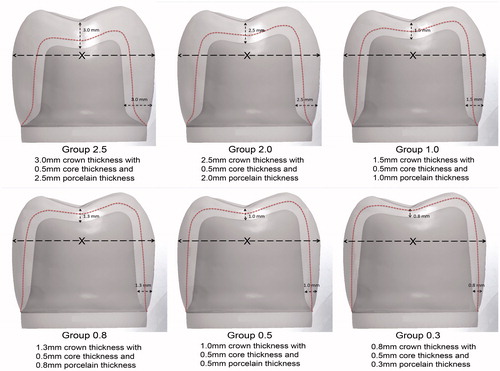
Table 1. Porcelain layer thicknesses in the different groups.
Design and production of translucent zirconium dioxide cores and abutment dies
A metal die resembling a molar crown preparation was made for an all-ceramic crown with a 1.2 mm deep 120° cervical chamfer and 15° angle of convergence. The die was replicated using a silicone impression material (President®, Coltene AG, Altstätten, Switzerland). The impression was poured with die stone material (Vel-Mix, Kerr Corporation, Orange, CA) to create the master die. By using a double scan technique, the master die was scanned following scanning of a wax-up of a full anatomic crown with an occlusal thickness of 3.0 mm and an axial thickness of 3.0 mm. The scanning was carried out with a dental laboratory scanner (D900L, 3Shape, Copenhagen, Denmark) and the data were then transferred to a computer running computer-aided design (CAD) software (Autodesk, San Rafael, CA). By using the CAD software, the first crown/die complex was copied and adjusted virtually by decreasing the preparation depths and correspondingly reducing the crown thickness toward the dimension settings of the different six groups. In this way, the outer dimensions of the crowns in all groups were identical, but the preparation depths of the abutment dies differed to match the different crown thicknesses ().
Six different CAD files were thus produced and subsequently sent to a certified BruxZir milling center (Cosmodent AB, Malmö, Sweden) where they were used to produce 60 translucent zirconium dioxide cores of equal 0.5 mm-thickness (BruxZir® Solid zirconia, Glidewell dental laboratories, San Diego, CA). The CAD data were also used to produce 60 dies in six different preparation depths corresponding to the different six groups. All abutment dies were milled from a polymer material (Polyoxymethylene, Nordbergs Tekniska AB, Stockholm, Sweden).
Veneer build-up
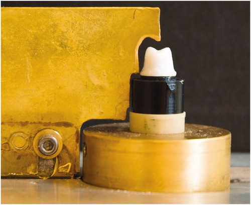
The porcelain was built up by hand, using a technique that has been described in detail in previous studies [Citation21,Citation22]. The zirconium dioxide cores were veneered with a porcelain recommended by the manufacturer (IPS e.max Ceram, Ivoclar Vivadent, Schaan, Liechtenstein). A custom-made knife () was used to standardize the outer shape and dimension of the crowns. Each crown underwent five porcelain firing cycles: liner, wash, dentin 1 and 2 and finally glaze firing. The firing cycles were carried out in a calibrated furnace (Ivoclar P 500, Ivoclar Vivadent, Schaan, Liechtenstein) according to the manufacturer’s recommendations.
Figure 2. A custom-made knife used for the porcelain build-up, with a zirconia core mounted on the abutment die.
Artificial aging
All crowns underwent three stages of artificial aging: thermocycling, storing in a 37 °C moist environment and cyclic preload.
Thermocycling
In the first stage of artificial aging, all crowns underwent 10,000 thermocycles in two water baths of a specially built thermocycling device at temperatures of 5 and 55 °C. Each cycle lasted for 60 s; 20 s in each bath and 10 s for transfer between the baths.
Cementation and storing in an incubator
The 60 crowns were cemented to the respective abutment dies using a methacryloyloxydecyl dihydrogen phosphate (MDP) containing resin cement Panavia F version 2.0 (Kuraray Medical Inc., Okayama, Japan) according to the manufacturer’s recommendations. The inner surfaces of the crowns were sandblasted using 50 µm aluminum oxide at a pressure of 2 bar, and then they were rinsed with water according to the manufacturer’s recommendations and as was suggested in a previous study by Kern et al. [Citation23] Before crown cementation, the abutment dies were roughened with air-abrasion (Basic Quattro IS, Renfert GmbH, Hilzingen, Germany) using 110 µm aluminum oxide at a pressure of 2 bar from a distance of 1.0 cm at a 90° angle to the abutment surface. Then they were steam cleaned and subsequently treated with ED PRIMER II A and B (Kuraray Medical Inc., Okayama, Japan). The crowns were cemented to the abutment dies with a standardized seating load of 15 N in the direction of insertion.
After cementation, the specimens were stored in a plastic container inside an incubator (Memmert Incubator, Memmert, GmbH, Schwabach, Germany) at a temperature of 37 °C for 60 d. All specimens were wrapped in a wet paper to create a moist environment like the oral cavity and to prevent desiccation of the luting cement.
Cyclic preload
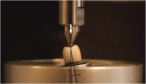
In the final stage of artificial aging, cyclic preload, a specially made preloading device was used (MTI Engineering AB/Pamaco AB, Malmö, Sweden) to subject the specimens to 10,000 load cycles between 30 and 300 N, with a load frequency of 1 Hz and with the specimens submerged in distilled water at 10° of inclination toward the tooth axis (). Preload was applied with a 4.0 mm Ø stainless steel ball placed on the occlusal surface of the crowns. A 0.2 mm thick plastic foil (PE-Baufolie, Probau, Bauhaus, Zug, Switzerland) was placed between the ball and the crown to distribute the load evenly and to prevent cone-crack formation as was suggested by Kelly JR [Citation24].
Figure 3. An illustration of the test set-up used for both the cyclic preload and the load to fracture. NB: The crowns were submerged in water, and a plastic foil was used to spread the load evenly over the loaded surfaces.
Load to fracture
All specimens were mounted in a test jig at 10° inclination, in the same way as during preloading, and as was used in previous laboratory studies [Citation9,Citation17,Citation21]. Specimens were loaded to fracture using a universal testing machine (Instron 4465, Instron Co. Ltd, Norwood, MA). The load was applied on the occlusal surface of the crowns with a 4.0 mm Ø stainless steel ball and a 0.2 mm thick plastic foil inserted between the ball and the crown. The crosshead speed was 0.255 mm/min, and the fracture was defined as a visible crack, load drop or an acoustic event, whichever occurred first. The acoustic event was determined by hearing a cracking sound that is accompanied by the changes in the load-path graph on a computer that is connected to the testing machine.
Analysis of fracture mode
Examination of the fracture surfaces and determination of fracture mode (complete, cohesive or adhesive fractures) were performed by a gross visual and microscopic (Leica DFC 420, Leica Microsystems CMS GmbH, Wetzlar, Germany) assessment by one investigator.
Statistical analysis
Loads at fracture were recorded and one-way ANOVA, Tukey’s test was used to analyze differences in fracture loads among the groups, IBM SPSS Statistics version 22 (SPSS Inc., Chicago, IL). The differences in fracture mode were analyzed using Fishers’ Exact Probability test. The level of significance was set to p values ≤ .05. All statistical analysis was done by an experienced professional statistician.
Results
All specimens were visually intact through all steps of the artificial aging, and neither fractures nor crack formations were detected in the crowns or the abutment dies. Loads at fracture, levels of significance and fracture modes are summarized in ().
Table 2. Load at fracture in Newton.
Fracture load
The one-way ANOVA showed significant differences in fracture loads among the groups. Group 1.0 showed significantly (p ≤ .05) highest fracture loads (mean 1540 N) in comparison with groups 2.5, 2.0 and 0.3 (mean 851, 910 and 1202 N).
There was no significant difference (p > .05) in fracture loads among groups 1.0, 0.8 and 0.5 (mean 1540, 1313 and 1286 N). Groups 2.0 and 2.5 showed significantly lower fracture loads in comparison with all other groups but with no significant differences between them (p > .05).
Fracture mode
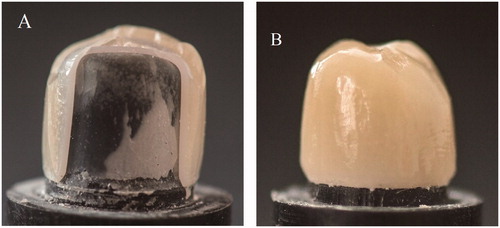
There were significant differences in the way the crowns fractured. Two kinds of fracture mode were seen visually, either complete fracture involving both the veneer and the core or cohesive fracture denoting fracture within the veneer only, i.e. chipping (). No adhesive fractures, involving the bonding area between the veneer and the core, were observed in the crowns under the light microscope. All crowns in groups 2.5 and 2.0 and more than 80% of the crowns in groups 1.0, 0.8 and 0.5 showed cohesive fracture mode. Conversely, there were significantly (p ≤ .05) more complete fractures in group 0.3 compared to all other groups.
Figure 4. Example of the two fracture modes: (A) Complete fracture (B) Cohesive fracture.
Discussion
Despite the fact that recently developed zirconium dioxide materials are more translucent than traditional Y-TZP, the improvements may be esthetically insufficient for use without adding porcelain. From a mechanical point of view, however, it has been suggested that the veneering porcelain should be kept to a minimum to avoid chip-off fractures commonly seen on traditionally veneered reconstructions based on Y-TZP [Citation1,Citation5]. The optimal design for such translucent reconstructions, however, is still an open question. The results of this study suggest that changes in the thickness of the porcelain layer have a significant influence on fracture strength of translucent zirconium dioxide crowns. Thus, the null hypothesis of the study was rejected.
The porcelain veneer thickness in the range of 1.0–2.0 mm on the traditional Y-TZP core is commonly recommended by the manufacturers to protect porcelain against fracturing and to achieve a clinically acceptable esthetic appearance by masking the underlying white opaque Y-TZP. The results of this study showed that the reduction of the porcelain layer, from 1.0 to 0.5 mm, lead to numerically but not significantly decreased loads at fracture, still being within the range of what might be considered clinically sufficient. Of 1000 N or more have been suggested to be an adequate safety limit for long-term durability of the crowns for most patients in all areas of the mouth [Citation24–26]. At porcelain thickness of 0.3 mm only, the difference in fracture loads became significant, but the loads the crowns endure before fracture are still within what is considered clinically sufficient. Consequently, all crowns with porcelain thickness thinner than recommended passed the safety limit and showed satisfactory results regarding fracture load. Most crowns with a porcelain thickness of 2.5 or 2.0 mm, on the other hand, showed fracture loads less than 1000 N. One explanation may be that the strength of a ceramic material is greatly influenced by the volume of material under stress. The increased volume presents more flaw populations including different flaw sizes and shapes, with a higher probability that a critical flaw would be present where the highest stresses are concentrated during loading. Consequently, this results in lower strength. Another possible explanation is that thicker layers of porcelain receive less support from the core than thinner ones, for geometrical reasons, and consequently become subjected to greater tensile forces that are especially detrimental to the brittle porcelain. Furthermore, all crowns of these two groups 2.5, 2.0 showed cohesive fractures in the porcelain, leaving the zirconia core visually intact. This result is consistent with studies showing an increased risk of cohesive porcelain fractures where the zirconia core is die-shaped rather than anatomically shaped, leaving the porcelain unsupported in thick layers [Citation8,Citation9,Citation16].
The results of this laboratory study showed that the most common fracture mode was similar to those seen when investigating clinical failures, cohesive fractures involving fracture of thin flakes of porcelain within the surface of the veneer only [Citation1,Citation5]. This fracture mode is quite different from so-called cone cracks, sometimes seen in laboratory studies. This implies that the loading of the anatomically shaped specimens was adequate. Further investigations using fractography, however, might give detailed information on fracture mode.
Previous studies have attempted to classify cohesive fractures by their size and how they affect function and what kind of intervention is needed if any [Citation27,Citation28]. In this study, further analysis of the severity of cohesive fractures was not possible as the observation of how a chip affects the function and the decision on whether an intervention is needed or not, depends for instance on neighbor teeth, antagonist as well as patient expectations.
The crowns with 0.3 mm porcelain showed, however, a majority of complete fractures, suggesting that since the porcelain layer was so thin, no tensile stresses are built up within this thin layer. Thus, the full impact of the load is transferred to the core, making it the limiting factor for the strength of the crowns rather than the porcelain. In this study, the zirconia cores were only 0.5 mm thick, which is the thinnest dimension recommended for this type of crown according to the manufacturers. This recommendation was further supported in a study by Nakamura et al. [Citation29]. If the core had been thicker, the loads at fracture might have been substantially higher, even for the groups with the thinnest porcelain. As was reported by Wakabayashi et al., fracture resistance of veneered alumina disks increases and fracture sites shifts from the veneer to the core as the core/veneer ratio increases [Citation30]. Although that study was investigating a different core material with a different methodology compared to that of this study, the results of this study support the findings of that previous study. With that in mind and to gain increased overall strength of porcelain-veneered translucent zirconium dioxide crowns, it would be interesting to study the combination of thicker cores and a 0.3 mm micro-veneering layer of porcelain in future research projects.
Previous studies have investigated the role of the overall thickness (core/veneer) on residual stress formation in porcelain-veneered zirconia using mathematical analysis of a bilayer model and FEA of spherically shaped specimens [Citation12,Citation13]. This study confirmed previous results but also added information based on clinically complex shaped crowns on tooth-like abutments. It was shown in previous studies that a thinner overall thickness of laminated specimens results in lower levels of stress formation during cooling of the material after firing. Since a thinner overall thickness in this study also was followed by a thinner porcelain layer, the higher fracture loads were probably dependent on lower stress formations in the thin porcelain compared to thicker porcelain. During the cooling phase after firing, the surface portion of a thicker porcelain layer will be cooled faster than the bulk material close to the zirconia core, since the zirconium dioxide material has extremely low thermal conductivity compared to a metal coping [Citation12]. If the surface portion of the porcelain is solidified before the bulk material, then stress formations will occur when the bulk continues to shrink after solidification of the surface layer, resulting in a residual stress zone prone to cohesive chip-off fracture under the surface layer of the porcelain. The probability of such residual stresses might be lower the thinner the porcelain is. Although slow-cooling protocols are used today to avoid the problem with residual stresses, thinner layers might contribute to lowering these residual stresses during cooling. Further studies, using FEA for instance, are needed to be performed to confirm this explanation.
It was, however, shown in a previous study that fracture strength of laminated dental ceramics is not sensitive to the core/veneer thickness ratio [Citation31]. That study suggested instead increasing the crown strength by adding thicker porcelain layers, keeping the core thickness as thin as possible. Those conflicting results might be explained by that a different core material was used in that study (lithium disilicate) and the total thickness for the specimens tested was 1.5 mm, with the thickest porcelain layer thickness of 1 mm only. Hence, the core material used in that study is not associated with the cooling problems seen with zirconium dioxide, and the veneer thickness was not exceeding the optimal porcelain thickness of 1 mm.
The preparation of abutment dies in this study was made with an anatomical occlusal shape to mimic the clinical situation. The preparation design used, with a cervical chamfer, was the same for all groups in accordance with the manufacturer’s recommendations. To obtain mechanical support comparable to that in real clinical situations, all crowns were cemented onto abutment dies made of a material with mechanical properties and a modulus of elasticity close to dentin. In that way, the risk of unrealistically high fracture loads of the crowns or fracture of abutments would be reduced as was investigated in previous studies [Citation32–35]. Previous studies have shown the deleterious impact of the laboratory thermocycling on the integrity of bonding between restorative materials and cement [Citation36,Citation37]. Therefore, the crowns were cemented using a recommended MDP containing resin cement after thermocycling stage to prevent partly loose crowns during the pre-load and load to fracture tests.
In this study, the proper thickness of porcelain veneer was built-up manually on the cores by one operator. It is well known that manually built-up veneers are never completely identical between the crowns because the ratio of porcelain powder and liquid plus the compaction process leads to different shrinkage and flaw populations. Consequently, the strength will always differ to some extent between individual specimens. The over-press veneering technique might provide more standardization in the veneering process in comparison with manually build-up technique. However, using manually build-up veneering technique is the dominating technique in dental labs compared to the over-press technique, the latter uses quite different ceramic materials (glass or hybrid) than commonly used feldspathic porcelain. So, manually build-up veneering technique is a preferable method based on the used materials in this study. Furthermore, there is no absolute consensus on the reliability of the over-press technique [Citation38–40]. When the veneers are fired under controlled laboratory conditions, in using manually build-up technique, any differences will have only minor effects on fracture strength of the crowns. In the study, the proportions of porcelain powder and liquid were measured and standardized within the crowns of the same group and between different groups according to the manufacturer’s recommendations.
Different protocols for the artificial aging procedures have been suggested in previous studies [Citation41,Citation42]. Fatigue protocols aim to simulate the various complex forces ceramic restorations would be subject to in a real clinical situation. It is well known that all-ceramic restorations are prone to continuous slow crack growth as a result of low continuous cyclic loads in a wet environment, resulting in stress corrosion at the crack tips of critical flaws. Thermocycling was used to mimic the influence of stresses that develop during the function, while the possible effects of the physical process of chewing were produced by cyclic preload with the specimens submerged in water. Nevertheless, there is no clear evidence on what aging protocol that resembles the aging in the clinical situation. Furthermore, there is no consensus regarding the effectiveness of these aging tests as some fail to show a direct relationship between the fatigue procedures and fracture loads of dental ceramics [Citation43]. In this study, however, thermocycling and preload tests were adopted from previous studies conducted by the same research group to allow for comparison of the results of these studies [Citation9,Citation17,Citation32].
In this study, static load to fracture test was used to assess fracture strength of the crowns. The crowns were mounted with a 10° of inclination relative to the load direction. This angle of inclination has been used in many previous studies and was initially suggested by Yoshinari and Derand [Citation9,Citation17,Citation21]. A more eccentric loading angle might have been favorable to evaluate fracture strength of the crowns. However, the test set up was adopted from previous studies to make comparisons possible.
There are always limitations in all laboratory studies. A full clinical scenario in respect of the performance of restorations can be seen in a clinical setting only. It is hard to extrapolate clinical results from the static loading test alone. Therefore, the results of this study are needed to be confirmed clinically.
Conclusions
Within the limitations of this laboratory study, the following conclusions can be drawn: translucent zirconia crowns can be veneered with minimal thickness layer of 0.5 mm porcelain without showing significantly reduced fracture strength compared to traditionally veneered (1.0–2.0 mm) crowns. Fracture strength of micro-veneered crowns with a layer of porcelain (0.3 mm) is lower than that of traditionally veneered crowns but still within range of what may be considered clinically sufficient. Porcelain layers of 2.0 mm or thicker on translucent zirconium dioxide result in significantly decreased fracture strength of the crowns compared to 1.0 mm or thinner and should, therefore, be used where the expected loads are low only.
Acknowledgments
The authors give special thanks RH Dental ApS in Denmark for providing Panavia F version 2.0 cement material.
Disclosure statement
The authors declare no conflicts of interests relevant to this submitted manuscript.
Additional information
Funding
References
- Al-Amleh B, Lyons K, Swain M. Clinical trials in zirconia: a systematic review. J Oral Rehabil. 2010;37:641–652.
- Sailer I, Feher A, Filser F, et al. Five-year clinical results of zirconia frameworks for posterior fixed partial dentures. Int J Prosthodont. 2007;20:383–388.
- Heintze SD, Rousson V. Survival of zirconia- and metal-supported fixed dental prostheses: a systematic review. Int J Prosthodont. 2010;23:493–502.
- Lughi V, Sergo V. Low temperature degradation -aging- of zirconia: a critical review of the relevant aspects in dentistry. Dent Mater J. 2010;26:807–820.
- Larsson C, Wennerberg A. The clinical success of zirconia-based crowns: a systematic review. Int J Prosthodont. 2014;27:33–43.
- Quinn JB, Quinn GD, Sundar V. Fracture toughness of veneering ceramics for fused to metal (PFM) and zirconia dental restorative materials. J Res Natl Inst Stand Technol. 2010;115:343–352.
- Fischer J, Stawarczyk B, Tomic M, et al. Effect of thermal misfit between different veneering ceramics and zirconia frameworks on in vitro fracture load of single crowns. Dent Mater J. 2007;26:766–772.
- Rosentritt M, Steiger D, Behr M, et al. Influence of substructure design and spacer settings on the in vitro performance of molar zirconia crowns. J Dent. 2009;37:978–983.
- Larsson C, El Madhoun S, Wennerberg A, et al. Fracture strength of yttria-stabilized tetragonal zirconia polycrystal crowns with different design: an in vitro study. Clin Oral Implants Res. 2012;23:820–826.
- Kokubo Y, Tsumita M, Kano T, et al. The influence of zirconia coping designs on the fracture load of all-ceramic molar crowns. Dent Mater J. 2011;30:281–285.
- Bonfante EA, Rafferty B, Zavanelli RA, et al. Thermal/mechanical simulation and laboratory fatigue testing of an alternative yttria tetragonal zirconia polycrystal core-veneer all-ceramic layered crown design. Eur J Oral Sci. 2010;118:202–209.
- Swain MV. Unstable cracking (chipping) of veneering porcelain on all-ceramic dental crowns and fixed partial dentures. Acta Biomater. 2009;5:1668–1677.
- Guazzato M, Walton TR, Franklin W, et al. Influence of thickness and cooling rate on development of spontaneous cracks in porcelain/zirconia structures. Aust Dent J. 2010;55:306–310.
- Schmitter M, Mueller D, Rues S. Chipping behaviour of all-ceramic crowns with zirconia framework and CAD/CAM manufactured veneer. J Dent. 2012;40:154–162.
- Beuer F, Schweiger J, Eichberger M, et al. High-strength CAD/CAM-fabricated veneering material sintered to zirconia copings–a new fabrication mode for all-ceramic restorations. Dent Mater J. 2009;25:121–128.
- Alhasanyah A, Vaidyanathan TK, Flinton RJ. Effect of core thickness differences on post-fatigue indentation fracture resistance of veneered zirconia crowns. J Prosthodont. 2013;22:383–390.
- Johansson C, Kmet G, Rivera J, et al. Fracture strength of monolithic all-ceramic crowns made of high translucent yttrium oxide-stabilized zirconium dioxide compared to porcelain-veneered crowns and lithium disilicate crowns. Acta Odontol Scand. 2014;72:145–153.
- Moscovitch M. Consecutive case series of monolithic and minimally veneered zirconia restorations on teeth and implants: up to 68 months. Int J Periodontics Restorative Dent. 2015;35:315–323.
- Bomicke W, Rammelsberg P, Stober T, et al. Short-term prospective clinical evaluation of monolithic and partially veneered zirconia single crowns. J Esthet Restor Dent. 2017;29:22–30.
- Whitworth JM, Walls AW, Wassell RW. Crowns and extra-coronal restorations: endodontic considerations: the pulp, the root-treated tooth and the crown. Br Dent J. 2002;192:315–320, 323–327.
- Yoshinari M, Derand T. Fracture strength of all-ceramic crowns. Int J Prosthodont. 1994;7:329–338.
- Vult von Steyern P, Ebbesson S, Holmgren J, et al. Fracture strength of two oxide ceramic crown systems after cyclic pre-loading and thermocycling. J Oral Rehabil. 2006;33:682–689.
- Shahin R, Kern M. Effect of air-abrasion on the retention of zirconia ceramic crowns luted with different cements before and after artificial aging. Dent Mater. 2010;26:922–928.
- Kelly JR. Clinically relevant approach to failure testing of all-ceramic restorations. J Prosthet Dent. 1999;81:652–661.
- Helkimo E, Carlsson GE, Helkimo M. Bite force and state of dentition. Acta Odontol Scand. 1977;35:297–303.
- Waltimo A, Kononen M. Maximal bite force and its association with signs and symptoms of craniomandibular disorders in young Finnish non-patients. Acta Odontol Scand. 1995;53:254–258.
- Moraguez OD, Wiskott HW, Scherrer SS. Three- to nine-year survival estimates and fracture mechanisms of zirconia- and alumina-based restorations using standardized criteria to distinguish the severity of ceramic fractures. Clin Oral Invest. 2015;19:2295–2307.
- Pang Z, Chughtai A, Sailer I, et al. A fractographic study of clinically retrieved zirconia-ceramic and metal-ceramic fixed dental prostheses. Dent Mater. 2015;31:1198–1206.
- Nakamura K, Harada A, Inagaki R, et al. Fracture resistance of monolithic zirconia molar crowns with reduced thickness. Acta Odontol Scand. 2015;73:602–608.
- Wakabayashi N, Anusavice KJ. Crack initiation modes in bilayered alumina/porcelain disks as a function of core/veneer thickness ratio and supporting substrate stiffness. J Dent Res. 2000;79:1398–1404.
- Dibner AC, Kelly JR. Fatigue strength of bilayered ceramics under cyclic loading as a function of core veneer thickness ratios. J Prosthet Dent. 2016;115:335–340.
- Mahmood DJ, Linderoth EH, Vult Von Steyern P. The influence of support properties and complexity on fracture strength and fracture mode of all-ceramic fixed dental prostheses. Acta Odontol Scand. 2011;69:229–237.
- Yucel MT, Yondem I, Aykent F, et al. Influence of the supporting die structures on the fracture strength of all-ceramic materials. Clin Oral Investig. 2012;16:1105–1110.
- Aboushelib MN, Feilzer AJ, Kleverlaan CJ. Bridging the gap between clinical failure and laboratory fracture strength tests using a fractographic approach. Dent Mater. 2009;25:383–391.
- Oilo M, Kvam K, Tibballs JE, et al. Clinically relevant fracture testing of all-ceramic crowns. Dent Mater. 2013;29:815–823.
- Ehlers V, Kampf G, Stender E, et al. Effect of thermocycling with or without 1 year of water storage on retentive strengths of luting cements for zirconia crowns. J Prosthet Dent. 2015;113:609–615.
- Luthy H, Loeffel O, Hammerle CH. Effect of thermocycling on bond strength of luting cements to zirconia ceramic. Dent Mater. 2006;22:195–200.
- Guess PC, Bonfante EA, Silva NR, et al. Effect of core design and veneering technique on damage and reliability of Y-TZP-supported crowns. Dent Mater. 2013;29:307–316.
- Christensen RP, Ploeger BJ. A clinical comparison of zirconia, metal and alumina fixed-prosthesis frameworks veneered with layered or pressed ceramic: a three-year report. J Am Dent Assoc. 2010;141:1317–1329.
- Beuer F, Edelhoff D, Gernet W, et al. Three-year clinical prospective evaluation of zirconia-based posterior fixed dental prostheses (FDPs). Clin Oral Invest. 2009;13:445–451.
- Kohorst P, Dittmer MP, Borchers L, et al. Influence of cyclic fatigue in water on the load-bearing capacity of dental bridges made of zirconia. Acta Biomater. 2008;4:1440–1447.
- Anusavice KJ, Kakar K, Ferree N. Which mechanical and physical testing methods are relevant for predicting the clinical performance of ceramic-based dental prostheses? Clin Oral Implants Res. 2007;18:218–231.
- Sundh A, Molin M, Sjogren G. Fracture resistance of yttrium oxide partially-stabilized zirconia all-ceramic bridges after veneering and mechanical fatigue testing. Dent Mater J. 2005;21:476–482.