
 ?Mathematical formulae have been encoded as MathML and are displayed in this HTML version using MathJax in order to improve their display. Uncheck the box to turn MathJax off. This feature requires Javascript. Click on a formula to zoom.
ABSTRACT
Spillway is one of the most cost-effective energy dissipating structures used in dams which leads to dissipation of flow energy at the end of the structure. Scouring is a phenomenon occurring next to the hydraulic structures, and which can lead to deterioration and even collapse of such structures. One of the methods to control the scouring downstream of a dam is using riprap. In this study it was investigated the stability of riprap based on relative particle diameter downstream of spillways of four different categories of energy dissipators, namely simple flip bucket, dentated flip bucket, simple triangular sill, and dentated triangular sill. The experiments were performed in a rectangular test flume. Ripraps of the same density and of four different diameters were investigated at five discharges at the movement threshold. Results of the study suggested that the relative particle diameter was an important factor in stability of the riprap. Besides, in all of the four aforementioned spillways, the stability number at the movement threshold was found to decrease with increase in the relative particle diameter. For all of the relative particle diameters, use of dentates led to an increase in the stability number 11% and 7% in spillways with simple flip bucket and triangular sill respectively. Also, a formula for estimating relative particle diameter was proposed. The correlation coefficient of the results yielded by this formula and the laboratory results was found to be 0.9 and 0.6 for the spillway with simple flip bucket and the other three types of the spillways respectively.
Introduction
With the construction of high dams, spillways discharge the volume exceeding the capacity of the reservoir of a dam. Since the flow over a spillway is supercritical, the kinetic energy of the flow is very high at the end of the spillway. This can lead to erosion downstream of a spillway. Consequently, a spillway requires an energy dissipating structure at its end to reduce the excessive energy of the discharging flow, and consequently, minimize erosion and scouring downstream the spillway. A scour forming downstream of a hydraulic structure increases the flow underneath the structure causing the scour to move toward the structure. This can jeopardize the stability of the structure and that of other related structures and result in their failure (Magela, Citation2020).
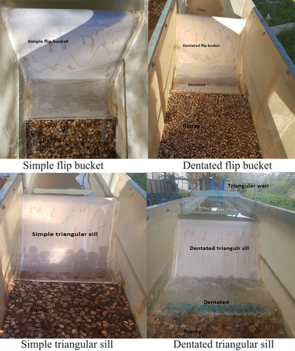
In recent years, the use of flip buckets has drawn more attention compared to other types of energy dissipators such as stilling basin, thanks to their economic advantages in certain geological and topographical conditions. Owing to better energy dissipation, a flip bucket in a submerged state outperforms one in a free-falling state and causes less scouring. Depicted in is an example of scour profile downstream of a flip bucket. Solid buckets and dentated buckets are two common types of flip buckets used in practice. These sorts of flip buckets are shown in . Flow is bent upwards prior to hitting the body of tailwater. In a dentated bucket, however, passing through the dentate, part of the flow energy is dissipated. In such flip buckets, the flow is spread over a larger region, leading to improvement in the dissipation of energy (Bhavan & Shahzafar Marge, Citation2010; Taraimovich, Citation1978; Vischer & Hager, Citation1995).
Figure 1. Scour profile downstream of a flip bucket.
Figure 2. A view of solid bucket.
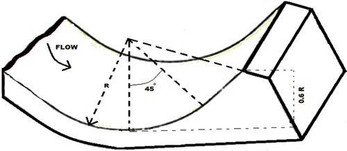
Figure 3. A sketch of a dentated bucket.
Examined in this study was the scour formed downstream of a solid and dentateted flip bucket. The dentated flip buckets were of rectangular and triangular shaped dentates straight and labyrinth forms. Scouring has been the subject of numerous studies. In the previous studies of the use of riprap for protection of hydraulic structures various methods have been utilized for designing the riprap, determining the average size of the particles, thickness of the riprap layer, placement depth of the riprap, the layout of the riprap, and the stability of riprap layers. Posey (Citation1974) considered the initiation of the motion of the riprap particles as the failure criterion. Scouring downstream of a flip bucket was studied by Mason and Arumugam (Citation1985). This souring results from the free falling jets. They argued that when a high-velocity flow passes a flip bucket, it’s bent upward. Consequently, the flow and its dissipation of energy vary with the trajectory angle of a bucket, which is why such a structure outperforms other sorts of energy dissipators. Worman (Citation1989) showed that if the thickness of the riprap layer was sufficient, the underlying filter layer would not be necessary. They conclude that the performance of a riprap system comprising multiple layers of different gradings is equivalent to that of an individual homogeneous layer of a less thickness. Parola (Citation1993) made use of a trilayer riprap with a colored intermediate layer. They considered the incipient failure of the riprap to be the exposition of the colored layer after 30 minutes of being stationary. Riprap thickness and characteristics of the filter layer are other design variables of riprap. The leaching propensity of the small particles of the substrate through the riprap pores can cause winnowing failure. A solution to prevent this mode of failure is to thicken the riprap layer and to place a filter between the riprap and the fine particles. How introducing along a trajectory channel of a series of prismatic dentates affects the scouring was experimentally investigated by Vischer and Hager (Citation1995). They observed that the application of a larger number of narrower dentates would reduce the scouring. They used prismatic dentates in their research and alleged that further research would be necessary to better understand the effect on the performance of flip buckets of dentate configuration.
Modifying and extending the Parola’s method, Yoon, Yoon, and Yoon (Citation1995) proposed a more accurate and more comprehensive method to design ripraps around bridge piers. In their method, the effect on riprap stability of various calibrators were incorporated as correction factors applied to the stability number. Chiew (Citation1995) used a time interval of 15 minutes to observe the failure of the riprap around bridge piers. They decided the instability of the riprap layer to be its overall failure. They maintained that removal of a number of particles from a riprap layer was not sufficient to be considered as its failure. Lauchlan and Melville (Citation2001) considered the performance of the riprap layer to be acceptable as long as its scour depth had not reached 20 percent of the scour extent of a bed not coated with riprap. Simarro, Chreties, and Teixeria (Citation2011) sought to determine the riprap size suitable for protection of bridge priers against erosion. In their research, they accounted for the hydraulic effect of the flow as well as pier spacing. Their experiments were conducted using four riprap sizes within a rectangular test flume set at a 7% slope. They found the pier spacing to be of little effect on the riprap size.In their experimental study, Eskandari, Heidarnejad, Masjedi, Purmohammadi, and Kamanbedast (Citation2020) examined how scour dimension downstream of a flip bucket was affected by dentates of various forms. According to their findings, incorporation of deflectors in the form of a labyrinth rectangular layout could reduce the scouring by 53%. Their results were in parallel with the empirical equations. Comparatively, in the case of control experiments, the Taraimovich equation yielded more accurate results. Likewise, as far as the labyrinth rectangular and triangular dentated buckets are concerned, the Damle-A and Damle-B equations predicted more accurate results. Ran, Liua, Dengb, Weib, and Longa (Citation2023), in this present, the prediction about the range of the free nappe is not complete. The studies show that the ejection angle is different at different locations of the outlet section, but the specific distribution of the outlet section velocity is still unclear. The measurement of free nappe range is mostly the direct measurement, how to accurately control is still difficult, and no systematic study has been made. Especially, the studies on the diffusion width of free nappe are few, the understanding of free nappe diffusion is not enough. In this article, the deflection degree of flow velocity at the outlet section in the lateral direction is quantified by the spread angle. Studied the distribution characteristic of spread angle through numerical simulation. The results show that the distribution characteristics and the maximum value of spread angle are affected by the change of flip bucket size and approach flow condition, and presented a set of equations for calculating the maximum angle. Numerous studies have investigated the diameter of stable riprap downstream of stilling basins and a number of formulas have been proposed for determining the riprap diameter, for example, Peterka relations (Peterka, Citation1968), Pilarczyk (Citation1990), Escarameia and May (Citation1992), Farhoudi and Valizadegan (Citation2004).
Flip buckets of different geometrical forms are different from each other in terms of their performance in dissipation of kinetic energy. The objective of this study is to experimentally investigate the stability of ripraps used downstream of spillways models of four different energy dissipators, namely simple flip bucket, dentated flip bucket, simple triangular sill, and dentated triangular sill. The dimensions of the spillways were selected in compliance to the USBR standard. Furthermore, to investigate the riprap stability downstream the spillway, ripraps of four different average diameters were used. The ripraps were all of the same density. The experiments were performed at five different discharges.
Materials and methods
Dimensional analysis
Covering with ripraps the downstream side of the spillways reinforces the bed and increases its resistance against the shear stress produced by the flow. One of the major parameters in investigation of the riprap resistance against the stresses induced by flow is the dimensionless parameter of stability number. To conduct the experiments of this study, considering the steady flow and constancy of fluid characteristics Equation (1), the following relation holds between the parameters affecting the scouring depth at a state of equilibrium:
In Equation (1), is denotes the placement depth of the riprap under unstable condition,
is stands for the flow velocity in unstable condition,
is represents the acceleration of gravity,
is denotes the average riprap diameter,
is stands for flow depth upstream the spillway,
is represents flow velocity upstream the spillway,
is stands for the initial depth of hydraulic jump downstream the spillway,
is denotes the flow velocity at the initial depth of hydraulic jump downstream the spillway,
is represents the flow depth over the bucket of the spillway and
is denotes the flow velocity over the bucket of the spillway. Equation (1) becomes dimensionless as follows:
In Eq. (2), is stands for the Froude number under the unstable condition of the riprap,
is represents the relative particle diameter under the unstable condition
is represents the relative energy loss in the spillway
is denotes the Froude number of the spillway. By combining the two parameters of Froude number and relative particle diameter of constant density in Equation (2), the stability number can be obtained as given in Equation (3):
In EquationEquation (3)(3)
(3) ,
is the stability number riprap,
is represents the acceleration of gravity,
is specific gravity of riprap that
is density of riprap and
is density of water,
is denotes the average riprap diameter and
is represents flow velocity upstream the spillway.
Experimental
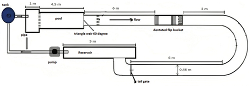
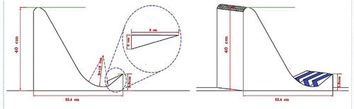
Experimental model was used to evaluate the effect on riprap stability downstream the flip bucket of geometry of the dentate at the end of the flip bucket. In order to carry out this study was used a plexiglass-made test flume of a length of 9 m and a width 46 cm and height of 50 cm (). The test flume belonged to the hydraulics laboratory of the Islamic Azad University of Ahvaz, Iran. The water circulation of the test flume was a closed loop system and water was supplied from a water tank next to the flume. The flip bucket model was built from plexiglass. It complied with the USBR standard and was 40 cm high, 53.4 cm long, with a bucket radius of 16 cm and an inlet length of 5.8 cm.
Figure 4. Schematic view of flume and installation position of the dentated flip bucket.
Furthermore, in order to investigate the effect of dentate, 16 triangular dentates each of which 8 cm long and 2 cm wide were installed at a spacing of 2.1 cm along the end of the flip bucket as per USBR standard (). The ripraps used in this study were round-edged material of the fixed specific gravity of riprap of 2.1 with relative dimeters of 9.52 mm, 11.23 mm, 12.7 mm, and 23.1 mm.
Figure 5. Sketch of dentated triangular spillway.
In order for determining the area of the riprap downstream of the flip bucket, the equilibrium-establishment-time experiment was conducted in the absence of riprap, and maximum scour hole dimensions were determined. The experiment took four hours. It was performed on a spillway positioned on a sand bed (without riprap) approximately 20 cm thick and at a maximum discharge of 15 lit/s and a depth of 12 cm. At the end of the experiment, the pump was switched off and the tailgate was shut and water in the channel was gently drained in order ot to affect the bed topography. Once water fully drained, the horizontal extent of the scour hole downstream of the spillway was measured. Based on the extent of the scour hole, a rectangular ripraps layout of 50 cm length and 46 cm width was selected for the experiments to be performed. Based on the studies carried out by Melville, Van Ballegooy, Coleman, and Barkdoll (Citation2007), the form of the riprap downstream of the spillway was considered to be rectangular and at the same level as the bed material. Likewise, considering the criteria given by Melville, Van Ballegooy, Coleman, and Barkdoll (Citation2007), the thickness of the riprap layer was selected to be twice the average riprap diameter.
All of the experiments carried out in this study were performed at the five discharges of 7, 8, 10, 12 and 15 lit/s. The discharge was measured using a triangular weir 60 degrees installed at the upstream end of the test flume. At the beginning of each experiment, the spillway of interest was positioned 6 meters down the upstream end of the test flume and the sediment on the bed of the channel was leveled to a constant slope using a moving screed. Subsequently, the riprap of a thickness of 250 and of the same level as the bed material was placed downstream of the spillway. Prior to switching the pump on, the tailgate was shut and clear water was gently led toward the channel to prevent any ripple or unevenness in the bed surface. The saturation time of the channel was between 20 to 30 minutes. After the rise of water level, and waiting a few minutes to ensure that the sediments had been wet, the pump was turned on at a low discharge. The discharge was then increased slowly to the desired magnitude by gradually opening the main gate valve on the inlet pipe of the stilling basin.
After the proper discharge was reached, the flow depth was gradually lowered using the tailgate to establish a flow condition which allowed for small movements of the riprap particles. After ensuring the uniformity of the flow depth along the flume, the movement manner of the riprap particles was inspected by eye. The condition under which the riprap particles slowly set in motion is called the movement threshold. At such a condition, the depth on the downstream is called the depth at movement threshold. At the end of each experiment, the pump was switched off and the end gate was shut and water was gently drained in order not to affect the bed topography. In all of the experiments, the secondary depth of the hydraulic jump downstream of the spillway was measured. For this purpose, after adjusting the discharge using the gate valve, the depth and velocity of flow were measured at a location one meter upstream of the spillways for each discharge. The one-meter clearance was to keep distance from changes of water level profile on the upstream side of the spillway. Subsequently, the tailgate was closed to raise tailwater depth. The tailwater depth was increased up to a level at which the hydraulic jump formed immediately past the incidence point of the water jet and flume bottom.
The purpose of creating such a hydraulic jump was to measure the flow depth after passing the bucket. The initial depth of the hydraulic jump could not be directly measured due to the presence of a significant amount of air within the flow at the downstream end of the bucket. The conjugate depth formula was used in order to measure the initial depth of the hydraulic jump, with the assumption of momentum being the same on both sides of the hydraulic jump and neglecting the friction losses and because the flow past the bucket is supercritical, with forming the hydraulic jump immediately after measuring the secondary depth of hydraulic jump (). Subsequently, the energy on both sides of the spillway was calculated by measuring the depths and velocities using the energy equation, and the energy loss of various trajectories were calculated Steiner, Heler, Hager, and Minor (Citation2008).
Figure 6. Properties on the spillway and riprap on the downstream.
Results
In all of the experiments, the flow depth was measured at the particle movement threshold downstream of the spillways. Also, for each riprap particle diameter was calculated the stability number at the movement threshold on the downstream side of spillways of four different categories of energy dissipators, namely simple flip bucket, dentated flip bucket, simple triangular sill, and dentated triangular sill. ().
Table 1. Results of the experiment at movement threshold of riprap.
Investigation of the riprap stability based on froude number at instability downstream of the spillways
In , a dimensionless chart of the riprap stability on the downstream side of spillways of four different energy dissipators, namely simple flip bucket, dentated flip bucket, simple triangular sill, and dentated triangular sill based on the Froude number at instability at five different discharges of 7, 8, 10, 12, and 15 lit/s for four different particle diameters, including 9.52, 11.23, 12.7, and 23.1 mm is given.
Figure 7. Investigation of the riprap stability based on the froude number at instability downstream of the spillways.
As can be seen in , for the same density, the Froude number at instability at movement threshold was the major factor affecting the stability of riprap particles. Likewise, the stability number at movement threshold decreased with increase in the Froude number for all of the four spillways studied. Furthermore, flow velocity increased with increase in Froude number at the instability depth at the movement threshold, leading to the reduction of stability of the riprap particles of all of the average diameters studied and for all of the spillway types experimented. Besides, as depicted in , the stability number was calculated to be 0.60, 0.56, 0.54, and 0.50 for the spillway with dentated triangular sill, dentated flip bucket, simple triangular sill, and simple flip bucket. Since the stability number depends on the instability depth, the instability depth of the riprap downstream the spillway with dentated triangular sill was found to be the smallest as compared to the other three types of the spillways examined.
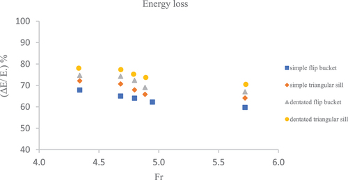
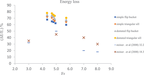
The spillway with dentated triangular sill is superior to the other three categories of the spillways in terms of hydraulics and energy loss. This may be attributed to the geometry of the spillway and presence at its end of the dentate that leads to the breakage and further compression of flow lines, and consequently, increase in the velocity at the throwing moment as well as a greater relative energy loss ()
Figure 8. Relative energy loss in all of the spillways.
compares the effect on the relative energy loss of the Froude number based on the results of this study with the results obtained by Steiner, Heler, Hager, and Minor (Citation2008). As can be seen in the , the energy losses obtained in this study are in parallel with the values obtained by that group of researchers.
Figure 9. Comparison of the results of this study with those obtained by Steiner, Heler, Hager, and Minor (Citation2008).
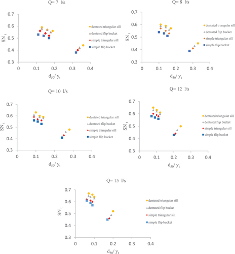
Riprap stability based on the relative particle diameter
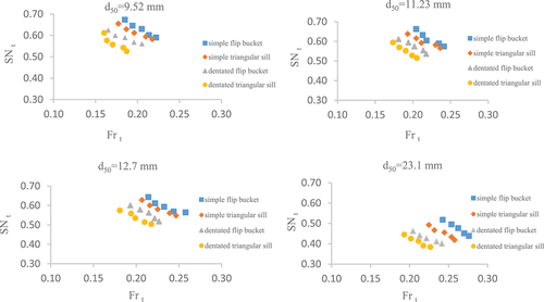
gives the riprap stability based on the relative particle diameter (d50/yt) at five discharges of 7, 8, 10, 12, and 15 liter per second for spillways of four different energy dissipators, namely simple flip bucket, dentated flip bucket, simple triangular sill, and dentated triangular sill with ripraps of the same density and at movement threshold. As can be seen, the relative particle diameter was an effective factor in the riprap stability. Besides, the stability number at the movement threshold of the four aforementioned spillways was found to decrease with increase in relative particle diameter. In other words, particle interlock is decreased with increase in particle size, causing decrease in particle stability. Furthermore, for all of the particle relative diameters examined, the stability number of the dentated triangular spillway was substantially larger than those of the other spillways surveyed, namely simple flip bucket, simple triangular spillway, and toothed flip bucket. Likewise, dentated triangular spillway offered a larger energy dissipation compared to the other three spillways and led to the formation of a lower instability depth and an increased stability in the riprap on the downstream.
Figure 10. Investigation of the riprap stability based on the relative diameter.
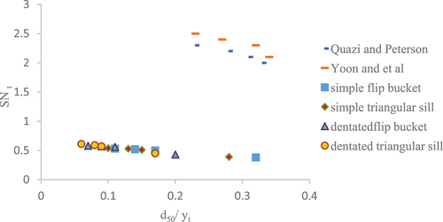
In order to compare the effect on the riprap stability of the relative particle diameter as obtained in this study with those of other researchers, the results of the studies performed by Yoon, Yoon, and Yoon (Citation1995), and Quazi and Peterson (Citation1973) were used. As can be seen in , the stability number measured for various relative diameters of this study are in line with the results of prior research.
Figure 11. Comparison of the results of this study with the results obtained by some other researchers.
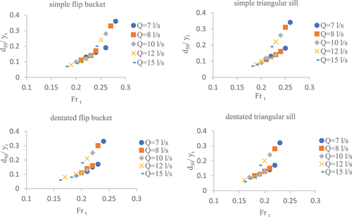
Investigation of the effect on relative particle diameter of the froude number
depicts the effect on relative particle diameter (d50/yt) of Froude number at movement threshold at five different discharges and for particles of the same density. As can be seen, the effect of relative particle diameter depends on the Froude number at movement threshold, meaning that with increase in the Froude number is increased the relative particle diameter. In other words, for a constant discharge, increase in Froude number leads to increase in the shear velocity of the flow and the riprap instability.
Figure 12. The effect of relative particle diameter based on the froude number.
To estimate relative particle diameter downstream of the spillways using the software SPSS, the relationship between the Froude number at movement threshold and relative particle diameter was obtained by nonlinear regression between maximum relative particle diameter, specific gravity of riprap and the Froude number at instability. Using the results obtained from analyzing the experimental data, Equation (4) was derived for the movement threshold:
The variables a, b and c were empirically obtained using the least squares method. After inputting the experimental data into the software SPSS and establishing a significant relationship between the dimensionless parameters, the coefficients in the EquationEquation (4)(4)
(4) , were computed for the four spillways of interest. The results are given in . The model was then constructed using the 70 percent of the data, with validation being performed using the remaining 30 percent. Listed in is the statistical analysis relevant to the evaluation of EquationEquation (4)
(4)
(4) , using the 30 percent of the data not used in the construction of the models.
Table 2. Estimating the parameters of eq. (4), for the four spillways categories studied.
Table 3. The statistical analysis of the suggested equations for estimation of the relative particle diameter.
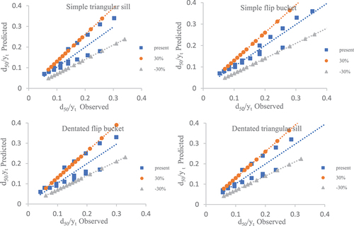
As can be seen in , to examine the accuracy of EquationEquation (4)(4)
(4) , comparison was made between the measured relative particle diameters and the values calculated using EquationEquation (4)
(4)
(4) , for the remaining 30% of the data. In , the two dashed lines −30% and + 30% represent the relative deviation with respect to the 45-degree line.
Figure 13. Correlation between the measured relative particle diameters and the values calculated.
A comparison of the RMSE as obtained in this study with the values obtained by other researchers is given in (Pagan-Ortiz, Citation1991). As can be seen, the results obtained in this study are in close agreement with those obtained by other researchers. Consequently, considering the error factor, the results of this study can be used in EquationEquation (4)(4)
(4) .
Table 4. Comparison of the results of the present study with those of the other researchers.
Conclusion
In this study were performed experiments to investigate riprap stability downstream of spillways of four different categories of energy dissipators, namely simple flip bucket, dentated flip bucket, simple triangular sill, and dentated triangular sill. According to the results of this study, dentated triangular spillway and simple flip bucket were of the largest and smallest stability numbers respectively. Besides, the relative particle diameter was found to be an effective factor in riprap stability, with the stability number decreasing with increase in particle diameter in all of the four spillway categories studied. In other words, at a constant discharge, increase in the Froude number results in increase in shear velocity of the flow and riprap instability. Besides, the stability number was calculated to be 0.60, 0.56, 0.54, and 0.50 for the spillway with dentated triangular sill, dentated flip bucket, simple triangular sill, and simple flip bucket. Also, was proposed a formula for estimating relative particle diameter. The correlation coefficient of the results yielded by this formula and the laboratory results was found to be 0.9 and 0.6 for the spillway with simple flip bucket and the other three types of the spillways respectively.
Notation
| yt | = | denotes the placement depth of the riprap under unstable condition |
| vt | = | stands for the flow velocity in unstable condition |
| g | = | represents the acceleration of gravity |
| d50 | = | denotes the average riprap diameter |
| y1 | = | stands for flow depth upstream the spillway |
| v1 | = | represents flow velocity upstream the spillway |
| v2 | = | denotes the flow velocity at the initial depth of hydraulic jump downstream the spillway |
| y2 | = | stands for the initial depth of hydraulic jump downstream the spillway |
| y | = | represents the flow depth over the bucket of the spillway |
| v | = | denotes the flow velocity over the bucket of the spillway |
| = | stands for the Froude number under the unstable condition of the riprap | |
| = | represents the relative particle diameter under the unstable condition | |
| = | represents the relative energy loss in the spillway | |
| = | Froude number | |
| = | the stability number riprap | |
| = | specific gravity of riprap |
Disclosure statement
The authors declare that they have no conflict of interest.
References
- Bhavan, M., & Shahzafar Marge, B. (2010). Burea of indian standards Central for hydraulic design of bucket type energy dissipators (Second Revision ed.). New Delhi: Bureau of Indian Standards.
- Chiew, Y. M. (1995). Mechanics of riprap failure. Journal of Hydraulic Engineering, ASCE, 121(9), 635–643. doi:10.1061/(ASCE)0733-9429(1995)121:9(635)
- Escarameia, M., & May, R. W. P. 1992. Channel protection downstream of structures. HR Wallingford Report SR 313.
- Eskandari, A., Heidarnejad, M., Masjedi, A., Purmohammadi, M., & Kamanbedast, A. 2020. Experimental investigation on the effect of different dentate shapes and configurations on scour dimension downstream of flip buckets. Water SA [Online]. 463: 458–464. 10.17159/wsa/2020.v46.i3.8656. ISSN 1816-7950
- Farhoudi, J., & Valizadegan, E. (2004). Bed protection criterion downstream of stilling basins. Yichang. China: ISRS.
- Lauchlan, C. S., & Melville, B. W. (2001). Riprap protection at bridge piers, ASCE. Journal of Hydraulic Engineering, 127(5), 30–38. doi:10.1061/(ASCE)0733-9429(2001)127:5(412)
- Magela, P. G. (2020). Spillway design - step by step (1st ed.). CRC Press. doi:10.1201/9780367816902
- Mason, P. J., & Arumugam, K. (1985). Free jet scour below dams and flip buckets. Journal of Hydraulic Engineering, 111(2), 220–235. doi:10.1061/(ASCE)0733-9429(1985)111:2(220)
- Melville, B. W., Van Ballegooy, S., Coleman, S. E., & Barkdoll, B. (2007). Riprap size selection at wing-wall abutment. ASCE, Journal of Hydraulic Engineering, 133(11), 1265–1269. doi:10.1061/(ASCE)0733-9429(2007)133:11(1265)
- Pagan-Ortiz, J. E. (1991). Stability of rock riprap for protection at the toe of abutments located at the flood plain Rep. No. FHWA-RD-91-057. Washington D.C: Feederal Highway Administration U.S. Dept. of Transportation.
- Parola, A. C. (1993). Stability of riprap at bridge piers. Journal of Hydraulic Engineering, ASCE, 119(10), 1080–1093. doi:10.1061/(ASCE)0733-9429(1993)119:10(1080)
- Peterka, A. J. (1968). Hydraulic design of stilling basins and energy dissipators engineering monograph no. 25. USA: USBR.
- Pilarczyk, K. W. (1990). Stabiuty criterisi for revetments, proc. Of 1990 national conf. On Hydraulics Eng, Am Soc Civ Eng, eds., San Diego, USA: HH Chang and JC Hill, pp. 15–26.
- Posey, C. J. (1974). Tests of scour protection for bridge piers. Journal of the Hydraulics Division, ASCE, 100(12), 17731783. doi:10.1061/JYCEAJ.0004132
- Quazi, M. E., & Peterson, A. W. 1973. A method for bridge pier riprap design. Pro. First Can. Hydraul. Conf., CSCE, Edmonton, AB, pp: 96–106.
- Ran, Y., Liua, C., Dengb, J., Weib, W., & Longa, Q. (2023). Numerical simulation study on spread angle in oblique cut flip bucket. Engineering Applications of Computational Fluid Mechanics, 17(1), 2236673. doi:10.1080/19942060.2023.2236673
- Simarro, G., Chreties, C., & Teixeria, L. (2011). Riprap sizing for pile group. Journal of Hydraulic Engineering, 137(12), 1676–1679. doi:10.1061/(ASCE)HY.1943-7900.0000458
- Steiner, R., Heler, V., Hager, W. H., & Minor, H. E. (2008). Deflector ski jump hydraulics. Journal of Hydraulic Engineering, 134(5), 571–562. doi:10.1061/(ASCE)0733-9429(2008)134:5(562)
- Taraimovich, I. I. (1978). Deformation of channels below high head spillways on rock foundations. Hydrotech Construction (USSR), 8(9), 917–923. doi:10.1007/BF02322089
- Vischer, D., & Hager, W. (1995). Energy dissipators. In A. A. Balkema (Eds.), Hydraulic structures design manual. No. 9 (p. 208). Rotterdam, The Netherlands: Taylor & Francis Group. doi:10.1201/9780203757512
- Worman, A. (1989). Riprap protection without filter layers. Journal of Hydraulic Engineering ASCE, 115(12), 1615–1630. doi:10.1061/(ASCE)0733-9429(1989)115:12(1615)
- Yoon, T. H., Yoon, S. B., & Yoon, K. S. 1995. Design of riprap for scour protection around bridge piers. 26th IAHR Congress, UK, 1: 105–110.