
 ?Mathematical formulae have been encoded as MathML and are displayed in this HTML version using MathJax in order to improve their display. Uncheck the box to turn MathJax off. This feature requires Javascript. Click on a formula to zoom.
ABSTRACT
Gabion steps on stepped spillways can be a suitable alternative to solid impermeable steps due to their economic advantages, ease of implementation, stability through water pressure reduction, and energy dissipation. This study explores hydraulic jumps and the rate of energy dissipation downstream of gabion stepped spillways under different flow regimes. Six stepped spillway models, including a solid spillway with solid steps and five models with gabion steps, were made with different step arrangements in a 26.6° slope (1 V:2 H) facility. The results showed that in stepped spillways with gabion steps and in the nappe flow regime, as a result of seepage flow through the pores of the aggregate and overflow passing the gabion step, there is an increased energy dissipation associated with a smaller sequent depth ratio, the relative length of jumps, and roller length compared to solid and impermeable steps. The reduction in the hydraulic jump depends on the flow regime and the arrangement of the gabion steps. For skimming flows, smaller energy dissipation rates were measured downstream of the gabion step. On average, when gabion steps are placed on all steps, the sequent depth ratio, jump length, and roller length decrease by 3.34%, 8.61%, and 8.14%, respectively, compared to solid steps. The maximum energy dissipation was measured at the downstream end of the gabion steps with a value of 74.4%, which is 5.03% more than that with the solid steps. On the solid stepped spillway, the nondimensional residual head was 4.65, and for the same flow conditions, the average dimensionless residual head on the gabion steps was 4.21.
Introduction
Stepped spillways are a set of steps that start from the crest of a spillway and continue to its downstream chute. The steps artificially roughen the bed and dissipate energy more than other types of spillways. Consequently, a lot of attention has been paid to this type of spillway in recent years. Included in this body of research is Rajaratnam (Citation1990), Rice and Kadavy (Citation1996), Chanson and Toombes (Citation2002), Gonzalez and Chanson (Citation2004), Felder and H (Citation2014), and Ghaderi and Abbasi (Citation2021). Also, in some studies such as Mero and Mitchell (Citation2017), AlTalib, Mohammed, and Hayawi (Citation2019), Felder, Geuzaine, Dewals, and Erpicum (Citation2019), Ghaderi, Abbasi, Abraham, and Azamathulla (Citation2020), and Ghaderi, Abbasi, and Di Francesco (Citation2021), the influence of the chute slope and the number of steps, the evaluation of the scale effect, and the effect of the geometry of the steps on flow characteristics over the stepped spillway were evaluated.
A simple and cost-effective construction type of stepped spillway is the gabion-stepped spillway (see ). A gabion-stepped spillway consists of rectangular baskets (often a galvanized steel mesh) filled with different-sized rocks (Stephenson, Citation1979).
Figure 1. Gabion stepped spillway, Robina, gold coast, Australia (Wüthrich & Chanson, Citation2014).
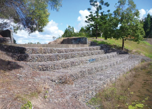
For low-to-medium head stepped spillways, gabions may be a suitable. They are stable, low cost, flexible, and porous (Chanson, Citation2001). The energy dissipation of the flow is high due to seepage flow through the porous body of the spillway, thereby reducing the need for a downstream stilling structure. In addition, gabion structures can be used for riverbed protection and bank stabilization. This type of spillway has more flexibility than its impervious counterparts and is stable against loads caused by water pressure (Zhang & Chanson, Citation2016).
Few studies have been performed to explore the flow characteristics and construction gabion spillways. Chinnarasri, Donjadee, and Israngkura (Citation2008) investigated the hydraulic characteristics of gabion stepped spillways. They showed that the energy dissipation at low discharge on a gabion-stepped weir is greater than that on a solid stepped spillway. Also, they studied the effect of chute slope on flow energy dissipation in gabion stepped spillways at three slopes of 30, 45, and 60 degrees. They found that a gabion stepped spillway with a steep slope has higher energy dissipation than one with a gentler slope. Salmasi, Sattari, and Pal (Citation2012) examined energy dissipation on a gabion stepped spillway, with nine physical models. The results indicated that at low discharge, the energy dissipation on impermeable steps is higher than on others. Increasing the porosity of steps from 38% to 42% and decreasing the slope from 1:1 to 2:1 increases the energy dissipation levels. Wüthrich and Chanson (Citation2014) conducted some experiments on gabion step spillways with a wide range of flow in order to investigate nappe, transition, and skimming flows. Large velocities were observed downstream of gabion stepped spillways and low rates of energy dissipation over gabion steps in comparison to impermeable steps. Zhang and Chanson (Citation2016) presented the flow resistance of a gabion stepped weir. They concluded that with similar flow conditions, the friction coefficient in the gabion weir is half of the value in the solid stepped spillway, and this value increases with the increase in flow discharge. Reeve, Zuhaira, and Karunarathna (Citation2019) used a numerical model to investigate the hydraulic characteristics of flow over stepped gabion weirs. Their results revealed that gabion steps can dissipate more energy than other geometry steps such as overlap, inclined, and pooled steps. Al-Fawzy, Al-Mohammed, Al-Fatlawi, and Al-Zubaidy (Citation2020) studied energy dissipation in a gabion stepped spillway, focusing specifically on a configuration with three steps. They found that energy dissipation increases with increasing flow discharge. The amount of energy dissipation has an inverse relationship with the porosity and the length ratio of the steps. Srinivas and Tiwari (Citation2022) evaluated the performance of three soft computing algorithms, such as the Backpropagation Neural Network (BPNN), Adaptive Fuzzy Inference System (ANFIS), and Deep Neural Network (DNN), for predicting oxygen aeration efficiency (OAE20) passing the gabion stepped spillway. The prediction results reveal that the DNN is a superior model with the following performance metrics: R2 = 0.975, RMSE = 0.034, and MSE = 0.001. The sensitivity analysis results indicate that porosity (n) is the most effective factor and spillway height (P) is the least effective parameter for oxygen aeration efficiency. As shown by Alabas, Al-Ameri, and Das (Citation2023), the milder slope model (1:3) (V:H) has a higher water surface and higher velocity than the steeper slope model (1:1), with an average of 9 and 8%, respectively, for a constant discharge. In addition, the through-flow ratio increased by about 27% when the porosity increased from 0.38 to 0.42.
It is apparent that a stepped spillway is a useful hydraulic structure for improving the hydraulic performance of a water-flow structure. Changing the steps from impermeable to gabion will have an effect on energy dissipation downstream of the stepped spillway. Recently, gabion steps were used on impermeable stepped spillways for ease of implementation and improved structural stability. This study considers gabion steps on a stepped spillway and their impact on the hydraulic jump, the sequent depth ratio, the relative length of the jump and roller length, and energy dissipation downstream of the stepped spillway.
Materials and methods
Dimensional analysis
Dimensional analysis is a method to find the relationship between dimensionless parameters. One method for dimensional analysis is the п-Buckingham method. The most important flow variables for energy dissipation are:
Fluid properties: dynamic viscosity (μ); density (ρ); and surface tension (σ).
Flow characteristics: main flow velocity (V=q/y), where q is discharge per unit width measured at the broad crested weir located at the upstream end of the chute and y is water flow depth, critical depth (yc), total energy upstream of the stepped spillway (E0), length of hydraulic jump (Lj), length of rollers (Lr), initial depth of the hydraulic jump (y1), and sequent depth of jump (y2)
Geometric properties: spillway height (P); step length (l); step height (h) and the porosity of the gabions (n).
A functional relationship connecting the dependent and hydraulic parameters of the stepped spillway with gabion steps as shown in Eq (1):
The rate of energy dissipation and jump characteristics are expressed as a function of the following dimensionless parameters as Eq (2):
Here, Re, Fr, and We are Reynolds numbers, upstream Froude numbers, and Weber numbers, respectively. The flow properties were recorded in the nappe, transition, and skimming flow regimes, for a range of discharges between 0.025 ≤ Q ≤0.054 m3/s with a corresponding Reynolds number between 1.8 × 10⁵ and 4.2 × 10⁵. So, the flow regime is entirely turbulent, so viscous effects can be ignored (Daneshfaraz et al., Citation2023). Considering that the dimensions of the steps are the same for all models, the h/l parameters can also be eliminated. Additionally, porosity is assumed to be constant in the gabion models (42%) and the influence of porosity variations is thus ignored. Furthermore, because the water depth on the edge of all steps in stepped spillway models exceeds 5 cm, the effects of the Weber number (We) were ignored (Chow, Citation1959; Daneshfaraz, Bagherzadeh, Ghaderi, Di Francesco, & Asl, Citation2021). With these simplifications, Eq (2) can therefore be rewritten as Eq (3):
Laboratory facilities and stepped spillway models
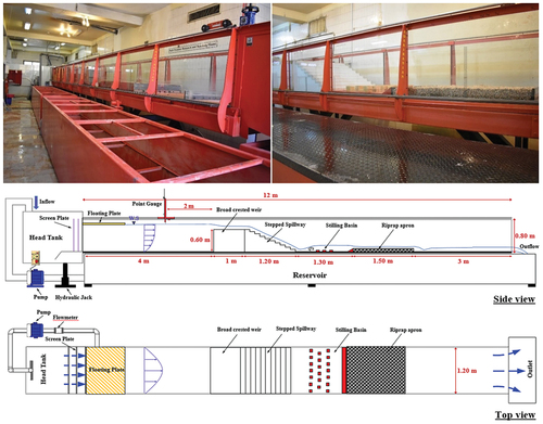
The experiments were performed in a rectangular cross-section flume with: length = 12 m, width = 1.2 m, and height = 0.8 m. The flume possessed a metal floor and plexiglass walls (see ). The slope of the flume was constant and equal to 0.001. The flow of the flume was generated by a pump, which had a 55 l/s flow capacity. A screen eliminated the large-scale flow turbulent structures at the channel inlet and the flow slowly entered the flume. An ultrasonic flow meter with a precision of ± 1 liter/s was used to measure the discharge. A broad-crested weir was in charge of controlling the flow at the upstream end of the chute. A gauge point determined the flow depth both upstream and downstream of the test section and at five points transverse to the flow. The gauge has an accuracy of ±1 mm. The first gauge was placed at a distance of 3P to 4P upstream of the broad-crested weir (P is the spillway height). The second measurement instrument, placed downstream of the hydraulic jumps, was used to determine the depths in those locations.
Figure 2. Schematic view of the experimental setup.
The tests were performed on a stepped spillway with a slope of 26.60°. The spillway consisted of 10 steps, each with a length (l) of 0.12 m and a height (h) of 0.06 m. The tests encompassed two stepped spillway configurations: solid steps and gabion steps. To assemble the gabion steps, a mesh with openings smaller than the filling material was covered around steel rods to create the gabion basket, which was then filled with gravel particles. First, a mesh with an opening that was smaller than the size of the filling material with dimensions of 1 cm was covered around steel rods to create the gabion basket, which was installed on the steps. The dimensions of the gabion basket were similar to the dimensions of the solid steps. The size of the stone particles inside the gabion box was selected. For this purpose, the main particle size criterion was based on the studies of Wüthrich and Chanson (Citation2014). As packing material for the gabion steps, natural round gravel with diameters of 21.8 mm to 27.9 mm with a mean diameter of d50 = 24.1 mm was used. The following Eq (4) was used to determine the porosity of gabion steps filled with particles:
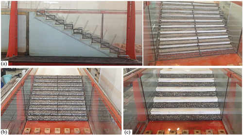
where Vvoid is the void volume and Vtotal is the total volume of the gabion box. To determine Vvoid, a water-displacement measurement was made (the volume measured by the displacement of water). Thus, both the total volume and the occupied volume of the gabion steps were determined. A porosity of 42% was used. Gabion steps with various arrangements were used, including placement on all steps (G1), placement on every other step (G2), every two steps (G3), placement on the top five steps (G4), and placing on the last five steps (G5). Downstream of the stepped spillway, a type III stilling basin was designed based on the USBR design criteria and for the inlet flow with a Froude number of 8. In order to prevent erosion downstream of the stilling basin and create a hydraulic jump inside the stilling basin, a gravel box with a length of 1.5 m and a width of 1.2 m filled with particles with an average diameter of d50 = 25 mm was used (Ghaderi & Abbasi, Citation2021). illustrates the placement of gabion steps on the stepped spillway.
Figure 3. The placement of gabion steps on the steps; (a) side view; (b) gabions on all steps; (c) gabions on every other step.
For each model, seven flow rates ranging from 25 to 54 l/s were tested in three regimes: nappe flow (25, 30, and 35 l/s), transition flow (40 l/s), and skimming flow (45, 50, and 54 l/s). Using the studies of Rajaratnam (Citation1990), it has been shown that the flow regime depends on the dimensionless variable of steps, h/l, and the normalized critical depth, yc/h, so that in yc/h ≥0.8, skimming flow happen. Here, yc is the critical depth, and h and l are the height and length of the step, respectively. So according to the Rajaratnam (Citation1990) suggestion, the flow regime was found, as provided in . shows a visual observation of the skimming flow regime on the solid and gabion steps.
Figure 4. Skimming flow regime on the solid and gabion stepped configuration (Q = 45 l/s; yc/h = 0.88).
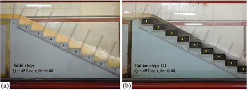
Table 1. Hydraulic characteristics and flow regime on stepped spillway models.
Research methods
For each test, after fabrication of the stepped spillway with gabion steps in a different arrangement, the pump was gradually increased until the desired flow rate was obtained. After the stabilization of the flow and the reduction of the fluctuations of the upstream flow level of the stepped spillway utilizing the downstream control gate, the hydraulic jump was created, located, and stabilized in the toe of the spillway models. The flow depths, including the upstream flow depth (approximately 2 m from the spillway), the critical depth on the edge of the first step, and the sequent depth of hydraulic jump, were taken at five transverse points of the channel by a gauge point with an accuracy of 1 mm. Then, the average of five points was used the specific depth. The hydraulic jump length and roller length, were recorded during the experiments by a meter installed on the channel wall with an accuracy of 1 mm. The criterion for measuring the jump length was from the beginning of the jump to the point where there were no surface fluctuations and the flow level was almost horizontal after the hydraulic jump. For the roller length at the beginning of the jump, it was considered to the point where the surface fluctuations were too high. The equation that relates the sequent depth y2/y1 to the initial Froude number is known as the Belanger momentum equation (Eq 5) and is used to calculate the initial depth of the jump given by (Maryami et al. Citation2021; Abnavi, Mohammadpour, & Beirami, Citation2023):
Fr2 is the Froude number flow after the hydraulic jump. Eqs (6)–(8) can be used to calculate upstream energy (section 0), the energy downstream of the stepped spillway (section 1), and the energy dissipation of the spillway (see ).
Figure 5. Sketch with dimensional annotations.
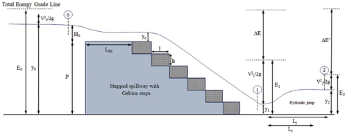
E0 is the total upstream energy, E1 is the total energy flow downstream of the stepped spillway, ∆E is the energy dissipation downstream of the stepped weir, P is the spillway height, yc is the critical depth, V1 is the jump’s initial velocity, and g is the acceleration of gravity. The variables of the laboratory model of the current research are presented in .
Table 2. Main variables for the physical models.
Results and discussion
The effect of gabion steps on the sequent depth ratio
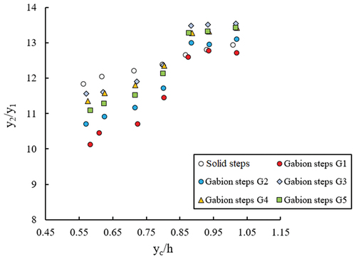
The variation of the sequent depth ratio (y2/y1) against the normalized critical depth (yc/h) for solid and gabion steps in different arrangements on the spillway is presented in . With the increase in flow discharge (increase in yc), the sequent depth ratio increases for all stepped spillway models. In low flow discharge (nappe flow regime), the values of sequent depth ratio decrease by using gabion steps compared to solid steps. This is due to seepage flow and its participation in the energy dissipation of the flow into the stilling basin. However, with the increase in discharge and the saturated gabion steps, the seepage flow does not appear to be much influenced by the energy dissipation, and the sequent depth ratio values are higher than with solid steps. On average, the sequent depth ratio in stepped spillways with gabion steps is less than that of solid steps. The G1 arrangement was most capable of reducing y2/y1 values compared to other gabion arrangements.
Figure 6. Variations y2/y1 versus yc/h for different gabion steps arrangements.
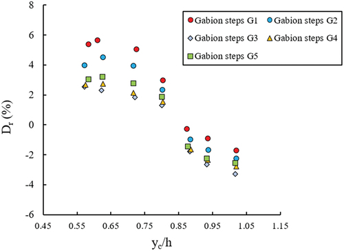
Taking into account the difference between the sequent depth ratio of the gabion steps and solid steps, a depth deficit parameter Dr, (i.e. Eq 9) for the reduction of the sequent depth is introduced by Ead and Rajaratnam (Citation2002) as:
where y*2 and y2 represent the sequent depth of a hydraulic jump for solid and gabion steps, respectively, with the same upstream conditions and yc/h. The plot of Dr versus yc/h is shown in . It can be seen that for all models, with an increase in flow discharge (increase in yc), the reduction coefficient decreases. In other words, the performance of stepped spillway models with gabion steps is in the low discharge and nappe regime (5.82% in the G1 model and in yc/h = 0.61). Also, case G1 gives the highest value of Dr compared to other arrangements. With the increase in yc/h, Dr becomes negative, which means that the sequent depth of the hydraulic jump with a gabion step is greater than for a solid step. On average, in model G1, the sequent depth decreases by 3.34%, and for the weakest arrangement (model G3), it decreases by 0.38% compared to solid steps.
Figure 7. Variations of the depth deficit parameter (Dr) versus yc/h in gabion steps with different arrangements.
The effect of gabion steps on roller and length of jump
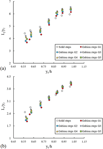
illustrates the variation of Lj/y2 and the relative roller length (Lr/y2) against the normalized critical depth (yc/h) for solid and gabion steps in different arrangements. It was found that the relative jump length and the relative roller length increase with the increase yc/h, for any mode of step of a stepped spillway due to the noticeable increase in jump turbulence. At low flow rates and in the nappe regime with yc/h < 0.725, the relative length of the jump and the relative roller length in gabion steps are less than the solid type ones. However, with the increase in discharge and skimming flow with yc/h > 0.88, the relative jump length and roller length are higher than with solid steps. But on average, the jump length and rolling length with gabion steps are less than with solid steps. The G1 model with the placement of gabions on all the steps has the best performance, and the G3 model with the placement of gabions on every other step has the lowest performance on decreasing the length of the jump and the roller length.
Figure 8. Variations Lj/y2 and Lr/y2 versus yc/h for different gabion steps.
Eqs (10) and (11) were used to calculate the reduction of the jump length (Tr) and roller length (Pr) between the gabion steps and solid steps:
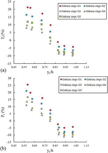
Here, L*j and L*r represent jump length and roller length downstream of the solid stepped spillway, respectively, and Lj and Lr represent jump length and roller length downstream of gabion steps, respectively, for the same yc/h values. presents the variation of Tr and Pr against yc/h. It can be seen that the reduction factor of jump length and roller length decreases with increasing yc/h in all models. In high discharge, the performance of the gabion step at reducing the jump length is not favorable. The average reduction ratio of jump length and rolling length for the best arrangement of gabion steps (G1) is 8.61% and 8.14%, respectively.
Figure 9. Variations of the reduction factor of jump length.
The effect of gabion steps on the energy dissipation and residual energy
An important consideration of design engineers is energy dissipation in stepped spillways and the amount of residual energy. The amount of energy dissipation (∆E/E0) in two conditions at the end of the stepped spillway and after the hydraulic jump is shown in . The present results are compared with experimental data from Wüthrich and Chanson (Citation2014) on gabion steps with the same chute slope (i.e. 26.6°). For all types of steps, with an increase in flow discharge, energy dissipation decreases. Energy dissipation in gabion stepped spillways can be divided into two parts: the nappe flow regime (low flow discharge) and the skimming flow regime (high flow discharge). In the nappe regime, the majority of the flow passes through the gabion steps. The energy dissipation is enhanced due by entrapment and friction. Consequently, the energy dissipation in the flow passing through gabion steps exceeds that of solid steps. With increasing discharge, seepage through the passage slowly converts to overflowing. When the flow regime changes into an overflow (skimming flow regime), the penetration of the flow into the porous gabions and friction in the porous structure are reduced. Consequently, the energy dissipation decreases.
Figure 10. Variations ∆E/E0 versus P/yc for solid and gabions steps in different arrangements.
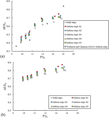
The placement of gabion steps (model G1) creates more flow interference and increases the resistance to the flow and thus has the highest energy dissipation. The present results are in good agreement with Wüthrich and Chanson (Citation2014). With low flow, energy dissipation in gabion steps is higher, and at high flow, energy dissipation is lower compared to solid steps (). From , some differences in terms of energy dissipation were seen for the gabion and solid steps which likely reflect the large energy dissipation rate after the hydraulic jump. Also, at high discharges, the performance of stepped spillway models with gabion steps improved after a hydraulic jump.
The following Eq (12) was used to calculate the difference in energy dissipation between gabion and solid steps:
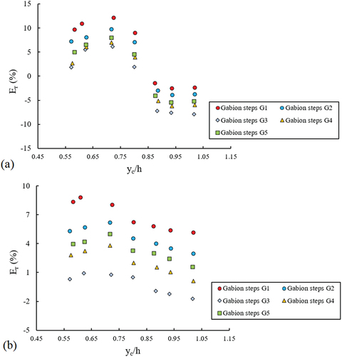
The symbols ∆E and ∆E* are the energy dissipations downstream of the stepped spillway with gabion and solid steps, respectively. shows the variations of Er against the yc/h in two conditions: at the end of the stepped spillway and after the hydraulic jump. It can be seen that Er decreases with increasing flow discharge in all models. For low flow discharge, gabion steps are better at increasing energy dissipation. On average, Er values with gabion steps (model G1) in the two states of the end of the stepped spillway and after the hydraulic jump are 5.03% and 6.81%, respectively.
Figure 11. Variations of Er.
The amount of residual energy (Hres) at the edge of the last is calculated and presented in . Eq (13) was used to calculate the amount of residual energy:
Figure 12. Relative residual energy versus yc/h for solid and gabion steps in different arrangements.
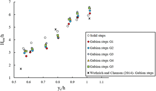
Here, V1, θ, y, and g are the velocity at the downstream end of the spillway, the slope, flow depth, and gravitational acceleration, respectively. From , the relative residual energy increased with the increase in flow discharge on all models. At low flow discharge (the nappe flow regime), gabion steps (model G1) have the least relative residual energy compared to other models. On average, the relative residual energy for the solid steps is Hres/yc = 4.65, while the average relative residual energy for the G1 model is 4.21. The present findings are in good agreement with Wüthrich and Chanson (Citation2014).
Conclusion
Step configurations are important for an optimized hydraulic design. In the present study, the hydraulic jump and energy dissipation stepped spillways with gabion steps were studied for slopes of 26.6°. Hydraulic jump characteristics such as sequent depth, jump length, and roller length, as well as the amount of energy dissipation and residual energy in the downstream of stepped spillway models, were examined. The results showed that gabion steps on stepped spillways in low flow discharge and in the nappe flow regime increased the energy dissipation and decreased the residual energy downstream of the stepped spillway and reduced the hydraulic jump compared to solid steps. The reduction in jump characteristics and increase in energy dissipation depends on the flow regime and the arrangement of the gabion steps. The following conclusions can be drawn:
The effect of the porosity of the gabion steps and the roughness of the aggregates does not appear to be much influenced by high flow discharge. With the increase in discharge and the saturated gabion steps, the relative sequent depth increases compared to the solid steps.
In low flow discharge with yc/h < 0.725 (yc is the critical depth and h is the step height), on average, the sequent depth of the hydraulic jump downstream of gabion steps decreases 5.82% compared to solid steps.
The best arrangement is when the gabion steps are placed on all the steps (G1), and the weakest arrangement is when the gabion steps are placed on every other step (G3).
The average reduction of the relative jump length and roller length in the best arrangement of gabion steps (G1) was calculated as 8.61% and 8.14%, respectively. However, with the increase in discharge and yc/h > 0.88, the relative jump length and roller length increased compared to solid steps.
In the best arrangement of gabion steps (G1), the average increase in flow energy dissipation at the end of the stepped spillway and after the hydraulic jump is 5.03% and 6.81%, respectively.
The lowest residual head is achieved with gabion steps. The solid stepped spillway has a dimensionless residual energy of about 4.65, which is the highest value recorded. In comparison, the gabion steps reveal an average dimensionless residual head of about 4.21 under same flow conditions.
The performance of the stepped spillways with gabion steps concerning energy dissipation was changed between 5.03% and 6.81%. Creating gabion on all steps (G1) has a significant effect on increasing energy dissipation, but it should be checked whether the size of the step with non-uniform gabion steps can affect the energy dissipation. To continue this research, it is suggested that researchers consider the non-uniform gabion steps and determine the optimal step size according to the flow regime, especially the conditions of the skimming flow and the maximum amount of energy dissipation. Also, the dimensional analysis parameters used for deducing equations for independent parameters might be useful for further work in the future.
Availability of data and material
Some or all data used during the study are available from the corresponding author upon reasonable request.
Disclosure statement
No potential conflict of interest was reported by the author(s).
References
- Abnavi, M. H. J., Mohammadpour, R., & Beirami, M. K. (2023). Laboratory investigation of hydraulic jump in divergent-convergent conversions. Flow Measurement and Instrumentation, 94, 102444. doi:10.1016/j.flowmeasinst.2023.102444
- Alabas, M. A., Al-Ameri, R., & Das, S. (2023). Investigation of flow characteristics in gabion stepped weirs. Water Supply, 23(2), 564–580. doi:10.2166/ws.2023.017
- Al-Fawzy, A., Al-Mohammed, F., Al-Fatlawi, T. J., & Al-Zubaidy, R. (2020). Dissipation energy of flow by stepped type gabion weir. IOP Conference Series: Materials Science & Engineering, 737(1), 012158. doi:10.1088/1757-899X/737/1/012158
- AlTalib, A. N., Mohammed, A. Y., & Hayawi, H. A. (2019). Hydraulic jump and energy dissipation downstream stepped weir. Flow Measurement and Instrumentation, 69, 101616. doi:10.1016/j.flowmeasinst.2019.101616
- Chanson, H. (2001). Hydraulic design of stepped spillways and downstream energy dissipators. Dam Engineering, 11(4), 205–242.
- Chanson, H., & Toombes, L. (2002). Air–water flows down stepped chutes: Turbulence and flow structure observations. International Journal of Multiphase Flow, 28(11), 1737–1761. doi:10.1016/S0301-9322(02)00089-7
- Chinnarasri, C., Donjadee, S., & Israngkura, U. (2008). Hydraulic characteristics of gabion-stepped weirs. Journal of Hydraulic Engineering, 134(8), 1147–1152.. doi:10.1061/(ASCE)0733-9429(2008)134:8(1147)
- Chow, V. T. (1959). Open channel hydraulics (pp. 680). New York: McGraw-Hill.
- Daneshfaraz, R., Bagherzadeh, M., Ghaderi, A., Di Francesco, S., & Asl, M. M. (2021). Experimental investigation of gabion inclined drops as a sustainable solution for hydraulic energy loss. Ain Shams Engineering Journal, 12(4), 3451–3459. doi:10.1016/j.asej.2021.03.013
- Daneshfaraz, R., Norouzi, R., Abraham, J. P., Ebadzadeh, P., Akhondi, B., & Abar, M. (2023). Determination of flow characteristics over sharp-crested triangular plan form weirs using numerical simulation. Water Science, 37(1), 211–224. doi:10.1080/23570008.2023.2236384
- Ead, S. A., & Rajaratnam, N. (2002). Hydraulic jumps on corrugated beds. Journal of Hydraulic Engineering, 128(7), 656–663. doi:10.1061/(ASCE)0733-9429(2002)128:7(656)
- Felder, S., Geuzaine, M., Dewals, B., & Erpicum, S. (2019). Nappe flows on a stepped chute with prototype-scale steps height: Observations of flow patterns, air-water flow properties, energy dissipation and dissolved oxygen. Journal of Hydro-Environment Research, 27, 1–19. doi:10.1016/j.jher.2019.07.004
- Felder, S., & H, C. (2014). Effects of step pool porosity upon flow aeration and energy dissipation on pooled stepped spillways. Journal of Hydraulic Engineering, 140(4), 04014002. doi:10.1061/(ASCE)HY.1943-7900.0000858
- Ghaderi, A., & Abbasi, S. (2021). Experimental and numerical study of the effects of geometric appendance elements on energy dissipation over stepped spillway. Water, 13(7), 957. doi:10.3390/w13070957
- Ghaderi, A., Abbasi, S., Abraham, J., & Azamathulla, H. M. (2020). Efficiency of trapezoidal labyrinth shaped stepped spillways. Flow Measurement and Instrumentation, 72, 101711. doi:10.1016/j.flowmeasinst.2020.101711
- Ghaderi, A., Abbasi, S., & Di Francesco, S. (2021). Numerical study on the hydraulic properties of flow over different pooled stepped spillways. Water, 13(5), 710. doi:10.3390/w13050710
- Gonzalez, C. A., & Chanson, H., 2004. Scale effects in moderate slope stepped spillways experimental studies in air-water flows, 8th National Conference on Hydraulics in Water Engineering, Australia. pp. 560.
- Maryami, E., Mohammadpour, R., Beirami, M. K., & Haghighi, A. T. (2021). Prediction of hydraulic jump characteristics in a closed conduit using numerical and analytical methods. Flow Measurement and Instrumentation, 82, 102071. doi:10.1016/j.flowmeasinst.2021.102071
- Mero, S., & Mitchell, S. (2017). Investigation of energy dissipation and flow regime over various forms of stepped spillways. Journal of Water and Environment, 31(1), 127–137. doi:10.1111/wej.12224
- Rajaratnam, N. (1990). Skimming flow in stepped spillways. Journal of Hydraulic Engineering, 116(4), 587–591. doi:10.1061/(ASCE)0733-9429(1990)116:4(587)
- Reeve, D. E., Zuhaira, A. A., & Karunarathna, H. (2019). Computational investigation of hydraulic performance variation with geometry in gabion stepped spillways. Water Science and Engineering, 12(1), 62–72. doi:10.1016/j.wse.2019.04.002
- Rice, C. E., & Kadavy, K. C. (1996). Model study of roller compacted concrete stepped spillway. Journal of Hydraulic Engineering, 122(6), 292–297. doi:10.1061/(ASCE)0733-9429(1996)122:6(292)
- Salmasi, F., Sattari, M. T., & Pal, M. (2012). Application of data mining on evaluation of energy dissipation over low gabion-stepped weir. Turkish Journal of Agriculture, 36(1), 95–106. doi:10.3906/tar-1011-1506
- Srinivas, R., & Tiwari, N. K. (2022). Oxygen aeration efficiency of gabion spillway by soft computing models. Water Quality Research Journal, 57(3), 215–232. doi:10.2166/wqrj.2022.009
- Stephenson, D., 1979. Gabion energy dissipaters. Proceedings of the International Commission on Large Dame, New Dehli: pp. 33–43.
- Wüthrich, D., & Chanson, H. (2014). Hydraulics, air entrainment, and energy dissipation on a gabion stepped weir. Journal of Hydraulic Engineering, ASCE, 140(9), 04014046. doi:10.1061/(ASCE)HY.1943-7900.0000919
- Zhang, G., & Chanson, H. (2016). Gabion stepped spillway: Interactions between free-surface, cavity and seepage flows. Journal of Hydraulic Engineering, 142(5), 06016002. doi:10.1061/(ASCE)HY.1943-7900.0001120