
 ?Mathematical formulae have been encoded as MathML and are displayed in this HTML version using MathJax in order to improve their display. Uncheck the box to turn MathJax off. This feature requires Javascript. Click on a formula to zoom.
ABSTRACT
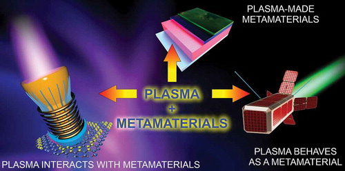
Plasma and metamaterials: what new advances in space micro-propulsion systems can they bring when used together? The aim of this concise review article is to attract attention of the space propulsion scientists and engineers, along with experts working in the fields of micro-machines, optics, communication, and other hi-tech devices, to the opportunities that arise from different possible combinations of plasma and metamaterials. Along with plasma-based techniques used for the fabrication of complex metamaterials, we examine two unusual plasma/metamaterial systems, namely when plasma interacts with a metamaterial, and when plasma itself features some properties of a metamaterial. The fundamental physics behind the principal processes that define the behavior of these systems is briefly outlined. Possible applications in space technology, mainly for micro-propulsion systems for Cubesats and small satellites are also sketched.
1. Introduction
The use of high-tech devices in aerospace technology, communication and optical systems, and micro-machines is showing a strong growth. Genuine breakthroughs in these and other knowledge-intensive sectors, however, often arise as a result of the discovery of new paradigms and physical principles that control the behavior of complex systems. Once physically realized, these breakthroughs can deliver significant benefits across many fields, and potentially change the entire landscape of the sector. Miniaturized space micro-propulsion systems that thrust small satellites and Cubesats in space is one example of technologies that changed how we explore and utilize outer space [Citation1–3]. Although significant progress has already been made in reducing the size and improving the performance of these devices, scientists and engineers continue their search for novel technologies and new physical principles to boost the efficiency and prolong service life of miniaturized space thrusters [Citation4–6], as well as for materials with advanced properties or those that exhibit unique behavior to enhance their durability [Citation7,Citation8]. Thrusters with an extremely long operational life can significantly increase the economic benefit that can be derived from space assets, and are essential for interplanetary probes and possible manned missions to Mars [Citation9–11].
While the modification of thruster designs and the development of more robust materials will sustain continuous incremental progress in miniaturized space propulsion systems, more dramatic advances may be needed to bring the technology to the level that is needed to realize constellations of thousands of small satellites for e.g. Earth observation or communication [Citation12]. In search of potential solutions, we will examine several approaches that rely on the synergistic application of plasma and metamaterials in complex, integrated systems.
Why plasma? Plasma is an inherent component of most types of miniaturized space propulsion thrusters, since these systems use plasma as the main operational medium to ionize and accelerate propellant and to create thrust.
In contrast, metamaterials are a novel, most promising class of structurally complex materials the use of which in aerospace technology is at the very early stages ()). The interaction between plasma and metamaterials may give rise to a range of interesting phenomena that may deliver tangible benefits to space micro-propulsion systems [Citation13]. In this paper, we will focus on so-called cold plasmas, i.e. the type of plasmas that features relatively low electron temperatures spanning typically from several eV to several tens of eV, and pressures spanning from several Pa to 1 atm (when the plasma is ignited at atmospheric conditions, directly in the ambient air or in a gas flow at atmospheric pressure).
We will focus on three ways in which plasma/metamaterial systems may boost some important characteristics of the above mentioned space-oriented technologies ().
Figure 1. (a,b) Smart metamaterials may be used for various space technology applications. From Ma et al. 2019 [Citation14]. Reprinted under term of CC BY License. (c) Combining plasma and metamaterials in three different ways: plasma produces metamaterials in a technological reactor; plasma interacts with metamaterials to control plasma and material parameters in e.g. plasma-based space propulsion thrusters, electromagnetic wave controllers, resonator arrays etc.; plasma itself behaves as a metamaterial for ultra-miniaturized, light-weight, durable electronics to control e.g. Cubesats. The three instances are interconnected and should be considered as possible embodiments of the same system
![Figure 1. (a,b) Smart metamaterials may be used for various space technology applications. From Ma et al. 2019 [Citation14]. Reprinted under term of CC BY License. (c) Combining plasma and metamaterials in three different ways: plasma produces metamaterials in a technological reactor; plasma interacts with metamaterials to control plasma and material parameters in e.g. plasma-based space propulsion thrusters, electromagnetic wave controllers, resonator arrays etc.; plasma itself behaves as a metamaterial for ultra-miniaturized, light-weight, durable electronics to control e.g. Cubesats. The three instances are interconnected and should be considered as possible embodiments of the same system](/cms/asset/d13b1a0f-1c00-4779-b19c-77e1612edcd4/tapx_a_1834452_f0001_oc.jpg)
Figure 2. Plasmas and metamaterials: what are the intertangled properties and processes, and how can plasma and metamaterials interact? Depending on the specific processes involved, various ways are possible. First, metamaterials may be produced using processes where plasmas are used to drive or enhance sputtering, etching, deposition, nucleation and growth of structures on material surfaces or in plasmas. Second, plasmas can interact with metamaterials at the interface, giving rise to the generation of large arrays of micro-scale electromagnetic fields, formation of distributed electronic elements such as ‘virtual’ antenna elements, and many others. Finally, plasma itself may display some characteristic features of metamaterials. In this case, many potentially important applications are possible such as, e.g., flexible control of electromagnetic energy fluxes at macro-scale via highly controllable ‘plasma-made’ metamaterial-like spatial structures. This article outlines specific features of these applications, along with the most important examples from the literature. Importantly, all these ways by which plasmas and metamaterials can come together may be beneficial for the future electric propulsion systems, including highly miniaturized thrusters for Cubesats
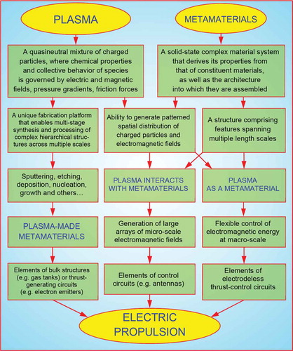
Combination of plasmas and metamaterials can result in various interesting effects classified by three groups with respect to the possible applications in electric propulsion, as shown in . First of all, the distinguished mobility of the plasma species, their extraordinary chemical activity and ability to respond to applied forces of different physical nature (like electric and magnetic fields, pressure gradients, friction forces, etc.) make plasmas a perfect tool to modify the geometrical, physical, and chemical properties of materials. Thus, plasmas can be considered as a unique fabrication platform that enables multi-stage synthesis and processing of complex hierarchical structures across multiple length scales [Citation15–17]. In this group, the main effect of coupling plasmas with metamaterials is described in terms of sputtering, etching, deposition, nucleation, growth, mixing, modification of the latter – the processes which result in the generation of plasma-made metamaterials. In the research conducted by Kang et al. [Citation18], the three-dimensional polymeric mechanical metamaterials were fabricated by interference lithography with the assistance of plasma etching. In the electric propulsion, this approach can be very beneficial in designing the elements of bulk structures (e.g. gas tanks). At the same time, the plasma-enhanced technologies of oxide and carbon nanostructure growth [Citation19,Citation20] can be applied for the thrust-generating circuits (e.g. electron emitters).
The second and third areas of the plasma and metamaterial utilization in electric propulsion are conditioned by the ability of plasmas to generate patterned spatial distribution of charged particles and electromagnetic fields, that result in the generation of complex plasma-based architectures comprising features spanning multiple length scales. Thus, in the experiments conducted by Navarro et al. [Citation21] the effect of a low-pressure argon plasma on split ring resonator (SRR) metamaterial is pronounced by shifting the SRR resonance to higher frequencies. Iwai et al. [Citation22] designed a tunable device with the extraordinary wave transmission, which consists of a plasma array and a negative-permeability metamaterial. Ji et al. [Citation23] proved that the combined coating of plasma and metamaterial can produce the effect of broadband reduction of the radar cross section (RCS). After studying the conditions of the plasma formation between coupled dielectric resonators (DRs), a conclusion about the future applications of the structure as a frequency selective filter can be made [Citation24]. At the same time, the experiments carried out by Liu et al. [Citation25] and Sakai et al. [Citation26] with the single-layer metamaterials illuminated by microwave pulses provided a useful guideline for designing metamaterials in high-power microwave systems. These examples illustrate the implementation of effects that arise when plasmas interact with metamaterials; they fall into the second group of plasma/metamaterial interactions. The third group represents examples of processes that arise when plasmas show characteristic properties and behaviors of metamaterials [Citation27]. A comprehensive review of examples that fall into this group is provided by Sakai and Tachibana [Citation28]; a particular application of plasma metamaterials as cloaking and nonlinear media should also be mentioned here [Citation29]. An interesting design of a metamaterial-inspired feather-light artificial plasma horn antenna was reported by Kizhakooden et al. [Citation30]. Here, the array of very thin copper wires produced plasma sheets, which allowed generating almost the same radiation characteristics as that of an equivalent conventional metallic horn. The last group provides several good examples of the flexible control of electromagnetic energy at macro-scale, which can be used in developing elements of electrodeless thrust-control circuits.
Specifically, in this review we will focus on three possible ways in which plasma/metamaterial systems can be used:
Plasma-made metamaterials, i.e. the system where plasma is used as a medium that drives the synthesis and assembly of a metamaterial;
Systems where plasma itself shows characteristics and behaviors of a metamaterial;
And finally, systems where plasma interacts with metamaterials to generate novel device properties and features.
Rather than providing a comprehensive review of the field, we will focus on several key aspects of these systems: (i) what are the central physical features and intrinsic processes behind each system; (ii) what primary advantages can such a system afford to the space thrust systems; and (iii) what are the trends for such a system. Interested readers would be able to find further details for these concepts in the referenced publications.
Discussions of applications and benefits will be centered around advanced space micropropulsion systems designed to drive and control Cubesats and small satellites. The latter require propulsion systems with extremely low mass and size to be accommodated inside spacecraft of one to several kilograms in mass and about 10 cm in dimension [Citation31–33]. Additional requirements include exceptionally high durability and service life to operate e.g. around Mars [Citation34] or in the capacity of miniaturized orbital observatories carrying expensive, precise astronomical [Citation12] and gravitational instruments [Citation35].
2. Plasma-made metamaterials
Metamaterials are a novel class of materials with a complex architecture comprising features spanning multiple length scales and a wide range of properties that are not feasible in other structures and materials platforms [Citation36]. Complex metamaterials and nano-assemblies have already been shown to have the potential to substantially extend the properties of existing materials and advance existing robust engineering materials to respond to the demands of emerging technologies [Citation37,Citation38]. Typically, they are produced using conventional template-based techniques where the metamaterial structure is being preset by a high-resolution sequential technique, e.g., an ultra-narrow coordinate-controlled ion or laser beam which is used to create a pattern of nucleation centers (such as pits, voids, etc.) one by one. Evidently, such a traditional, mechanistic approach may not be practical for the production of novel metamaterials and may not be compatible with techniques and materials used in the assembly of various operational elements of small satellites, from nano-electronics [Citation39] to structural components [Citation40,Citation41], photovoltaic elements [Citation42], sensors [Citation43], elements of miniaturized thrusters and gas supply systems [Citation44]. The application of plasmas as a tool for the fabrication and assembly of a new generation of metamaterials may present a reasonable solution [Citation45].
2.1 Why plasma?
Indeed, plasma as a tool for materials synthesis and treatment delivers many unique features, including electric and magnetic fields to control material treatment [Citation46,Citation47], highly energetic particles capable of material removal [Citation48], reactive species for assembly and functionalization [Citation49,Citation50], magnetized electrons and others, making plasma a highly controllable yet versatile tool with very complex behavior [Citation51] ().
Not surprisingly, plasma can be used to organize multi-stage techniques to synthesize very complex, hierarchical, nano-structured materials.
With respect to the material processing, the distinctive and often unique features of plasmas are defined by the wide range of controls that can be used to modulate plasma parameters in a highly specific manner. Even the simplest plasma reactor, i.e. a vessel filled with a gas mixture and equipped with two electrodes (an anode and a cathode) to deliver energy from a DC source [Citation52], is a powerful tool that can be used to sputter, modify, deposit, and trim materials [Citation53]. The electric field that forms between two electrodes generates the electron avalanche in the discharge gap, thus creating a large number of electron-ion pairs. Here, the ions are considered as building blocks for material synthesis and modification, while the electrons sustain continuing ion generation. In a DC reactor, such as that described above, the igniting electrons are produced by the ions upon their interaction with the cathode. The power Pabs absorbed by the discharge gap results in the generation of plasma species with the density that can be defined as [Citation54]:
where uB is a Bohm velocity; M is the ion mass; Te is the temperature of electrons; εT is the total energy lost per electron-ion pair lost from the system; and S0 is the effective area for particle loss.
Transformation of the cathode into the plasma-containing vessel additionally increases the plasma density by changing the discharge to the hollow cathode discharge with the electrostatic [Citation55] and magnetic [Citation56] confinement of the charged particles. Here, density of the electrons emitted from the cathode surface nh0, ionization rate Kiz, density of the background gas na, the magnetic field B directed along the walls of the reactor, the diffusion coefficient Da, and size of the vessel L are related to the plasma density as [Citation57]:
Figure 3. Basic principles that govern plasma behavior. Reprinted with permission from Baranov et al., 2018 [Citation57]. Copyright Springer-Nature, 2018
![Figure 3. Basic principles that govern plasma behavior. Reprinted with permission from Baranov et al., 2018 [Citation57]. Copyright Springer-Nature, 2018](/cms/asset/6f319117-e4e7-45a1-9251-9f9e5e6377cb/tapx_a_1834452_f0003_oc.jpg)
To control the chemistry and density of gas species that are generated at different gas pressures within the same reactor, alternating electric field is applied to excite plasma in radiofrequency (RF) or microwave (MW) plasma discharges [Citation58].
By changing the gas pressure and bias potential, the arc mode of the discharge can be developed [Citation59], when large solid clusters or liquid droplets can be removed from the surface of one material, and moved to another area within the reactor to serve as building blocks for material synthesis or modification [Citation60]. The generated flows φgen(v,l,s) of the vapour, liquid, or solid material can be related to the initial flows φin(e,i) of the plasma electrons and ions through the coefficients describing the specified process:
Except for the material production, the plasma–wall interaction changes the surface potential with respect to the adsorption of new material. The plasma bombardment changes the energy of adsorption, which results in an increase in the density nai/n0 of species adsorbed by the surface [Citation61]:
where Pi is the partial pressure of the gas; ΣMi is the mass of the gas molecule; Ts is the surface temperature; kB is the Boltzmann constant; εai(εion) is the adsorption energy of the gas molecule, which is dependent on the energy of the bombarding ions.
Figure 4. Schematics of the energies and processes involved in the synthesis of carbon-based materials in plasmas. The growth model considers dependencies of the growth characteristics on the control parameters through the microscopic quantities. Complex interrelation of many elemental processes is also taken into account in the model to reflect graphene nucleation and growth, and formation of the array morphology. ‘VG’ stands for vertical graphene, a type of nanostructure that was used as a base model for the development of this flowchart (see more details in Baranov et al., Rev. Mod. Plasma Phys. 2019) Reprinted with permission from Carbon 2019 [Citation64]. Copyright Elsevier, 2019
![Figure 4. Schematics of the energies and processes involved in the synthesis of carbon-based materials in plasmas. The growth model considers dependencies of the growth characteristics on the control parameters through the microscopic quantities. Complex interrelation of many elemental processes is also taken into account in the model to reflect graphene nucleation and growth, and formation of the array morphology. ‘VG’ stands for vertical graphene, a type of nanostructure that was used as a base model for the development of this flowchart (see more details in Baranov et al., Rev. Mod. Plasma Phys. 2019) Reprinted with permission from Carbon 2019 [Citation64]. Copyright Elsevier, 2019](/cms/asset/20de8649-84fe-4848-bf18-69693bb7c9fe/tapx_a_1834452_f0004_oc.jpg)
Carbon-based materials are already widely applied in the aerospace industry. However, their potential applications are far from being fully explored, let alone exhausted, because of the large diversity of carbon nanostructures discovered in the last decades: fullerenes, nanotubes, nanowalls, cabbage- and flower-like nanostructures, to mention but a few [Citation62,Citation63]. Sharp edges characteristic of these structures make them prospective candidates for the field-emitting applications; whereas their large surface-to-volume ratio can be used for storage or catalytic purposes; while outstanding mechanical properties make it possible to use them to reinforce structural elements of devices and systems. To fabricate these materials, various physical effects must be brought together into sophisticated technological processes that cover a very wide range of the operation parameters: five orders of magnitude for gas pressure (1–105 Pa) and ion energy (0.1–104 eV), six orders for plasma density (1014–1022 m−3), etc.
shows an example of the chart of energies and processes involved in the synthesis of carbon-based materials in plasmas [Citation64]. This allows to use complex technological architectures where material trimming, growth, and functionalization processes are realized during plasma-enabled synthesis and assembly of e.g. vertical graphene nanosheets [Citation65].
In this case, the gas chamber is filled with a carbon-containing gas (CH4, e.g.) that serves as a source of carbon atoms that sustain the growth of vertical graphene structures in DC [Citation66], RF [Citation67], or MW [Citation68] discharges. The gas pressure is generally limited by the type of the plasma reactor used [Citation69]. For the growth of carbon-based structures, the gas mixture typically contains hydrogen which is necessary to etch the surface and to remove the hydrogen atoms from the hydrocarbon radicals adsorbed on the surface. To change the energy of adsorption of species, the bias potential is applied, which results in the development of the voltage drop Us across the sheath that, in turn, determines the energy εi of the ions [Citation70]. The ion bombardment changes the energies of adsorption and diffusion of the hydrocarbon radicals and hydrogen atoms across the surface, while the total effect of the ion energy and the density of the ion current ji directed to the surface, determine the whole temperature Ts of the substrate, thus allowing for the adsorption and diffusion processes to be tailored so that optimal conditions for the growth of nanostructures are maintained.
2.2 Plasma-made metamaterials: Examples
The application of plasmas in the production of metamaterials is based on the same general principles that underpin plasma-enabled nano- or microstructure synthesis. shows several examples of plasma-made materials and their potential application in aerospace technology, specifically for Cubesats.
Etching [Citation71,Citation72] (i.e. material sputtering in the presence of a chemically active reagent to weaken the atomic bonds on the surface of the material) and deposition [Citation73,Citation74] are the most applied technological operations where plasmas are used [Citation75]. The etching is usually employed for the selective removal of material components to reveal a matrix which can be subsequently filled with another material component to create a complex multi-material system with the necessary physical and chemical characteristics. ) illustrates the production of high-entropy-alloy nanoparticles (HEA-NPs) [Citation76]. Plasma-produced coaxial plasmonic metamaterials could operate in the UV/visible part of the spectrum [Citation77]. In the fabrication process, plasma is applied at the stage of reactive ion etching (RIE) after the electron beam lithography on Si, Si membranes or SiO2 substrates. In the experiment shown in ), a computer-designed lattice was written in the cured positive-tone photoresist on a glass substrate coated with gold via two-photon lithography. Then, the photoresist was used as a template for Cu electroplating. After removing the photoresist, the Cu matrix was exposed to plasma-enhanced chemical vapor deposition (PECVD) to obtain an a-Si coating [Citation78]. The ability of reactive plasma to etch and heat the sample surface was utilized by Chen et al. [Citation79] for the development of an isotropic IR metamaterial consisting of four-fold-symmetric 3D Split-Ring Resonators (SRR), as shown in ).
Figure 5. Several examples of plasma-made nanostructures and metamaterials. (a, b) Synthesis of high-entropy-alloy nanoparticles (HEA-NPs): (a) schematic comparison of a phase-separated heterostructure and a high-entropy-alloy structure, and (b) quinary HEA-NPs (PtPdRhRuCe) synthesized by a carbothermal shock method. Reprinted with permission from Yao et al., 2018 [Citation76]. Copyright American Association for the Advancement of Science, 2018. (c) Illustration of the fabrication process of 3-dimensional architected Cu-Si core-shell nanolattices. Reprinted with permission from Xia et al. [Citation78]. Copyright ASC, 2016. (d) The fabrication process of a 3D Split-Ring Resonators (SRR) using CF4 plasma dry-etching. Reprinted with permission from Chen et al. [Citation79]. Copyright Wiley, 2014. (e) Schematic representation of fabrication of isoprene-block-styrene-block-ethylene oxide block copolymer. The final structure is obtained by plasma etching the two remaining polymer blocks. Reprinted with permission from Vignolini et al. 2012 [Citation80]. Copyright 2012 Wiley
![Figure 5. Several examples of plasma-made nanostructures and metamaterials. (a, b) Synthesis of high-entropy-alloy nanoparticles (HEA-NPs): (a) schematic comparison of a phase-separated heterostructure and a high-entropy-alloy structure, and (b) quinary HEA-NPs (PtPdRhRuCe) synthesized by a carbothermal shock method. Reprinted with permission from Yao et al., 2018 [Citation76]. Copyright American Association for the Advancement of Science, 2018. (c) Illustration of the fabrication process of 3-dimensional architected Cu-Si core-shell nanolattices. Reprinted with permission from Xia et al. [Citation78]. Copyright ASC, 2016. (d) The fabrication process of a 3D Split-Ring Resonators (SRR) using CF4 plasma dry-etching. Reprinted with permission from Chen et al. [Citation79]. Copyright Wiley, 2014. (e) Schematic representation of fabrication of isoprene-block-styrene-block-ethylene oxide block copolymer. The final structure is obtained by plasma etching the two remaining polymer blocks. Reprinted with permission from Vignolini et al. 2012 [Citation80]. Copyright 2012 Wiley](/cms/asset/eda8343c-b034-4d66-8aba-4758d467c5b3/tapx_a_1834452_f0005_oc.jpg)
Figure 6. Quantitative characterization of plasma interactions with nanostructured surfaces. How do quantitative parameters of plasmas affect processes at the plasma-nanomaterial interface? The graphs illustrate the various types of ion density distributions at the plasma-nanostructure interfaces for different plasma densities ranging from 2.4 × 10¹⁸ m−3 to 1.23 × 10¹⁷ m−3, and surface bias of plasma-immersed nanostructures (20 and 50 eV). (a-c) Distributions of ion density along the lateral surfaces of nanotips in plasmas. For substrate bias Us = 20 V (the narrow sheath case), the effect of plasma-generated electric field is weak for high plasma density (a,b) and is quite noticeable at lower plasma densities (c). (d-f) For substrate bias Us = 50 V (the wide sheath case), the effect of plasma-generated electric field is quite strong at high plasma densities (d,e) and very strong at lower plasma densities (f). Reprinted with permission from Levchenko et al. 2005 [Citation81], Copyright AIP
![Figure 6. Quantitative characterization of plasma interactions with nanostructured surfaces. How do quantitative parameters of plasmas affect processes at the plasma-nanomaterial interface? The graphs illustrate the various types of ion density distributions at the plasma-nanostructure interfaces for different plasma densities ranging from 2.4 × 10¹⁸ m−3 to 1.23 × 10¹⁷ m−3, and surface bias of plasma-immersed nanostructures (20 and 50 eV). (a-c) Distributions of ion density along the lateral surfaces of nanotips in plasmas. For substrate bias Us = 20 V (the narrow sheath case), the effect of plasma-generated electric field is weak for high plasma density (a,b) and is quite noticeable at lower plasma densities (c). (d-f) For substrate bias Us = 50 V (the wide sheath case), the effect of plasma-generated electric field is quite strong at high plasma densities (d,e) and very strong at lower plasma densities (f). Reprinted with permission from Levchenko et al. 2005 [Citation81], Copyright AIP](/cms/asset/f2e23d76-8570-4d28-b432-f10828c3ad74/tapx_a_1834452_f0006_b.gif)
A 2D template of an SRR consisting of two arms and a connection pad was produced by the use of electron beam lithography, Ni/Au deposition, and lift-off processes. Then, the sample was exposed to CF4 plasma etching to induce spontaneous folding of the arms by bilayer residual stress. Vignolini et al. synthesized a 3D gold metamaterial based on block copolymer (BCP) self-assembly, as illustrated in ). In the process [Citation80], isoprene-block-styrene-block-ethylene oxide BCP was exposed to selective UV and chemical etching to remove isoprene; then, the thus-obtained matrix was filled with gold by electrodeposition. After that, a 3D continuous gold network was revealed by plasma etching of the two remaining polymer blocks. Apparently, these metamaterials can be used in aerospace technology assets requiring light but strong parts (e.g., Cubesat case and mechanisms), and light but reliable electronics.
Thus, the application of plasma-based technological environments for the production of various metamaterials is a quite efficient approach, as it has been illustrated in . However, the specific parameters of plasmas are extremely important for the plasma-enabled nanofabrication, and not surprisingly, the ratio of plasma-surface sheaths to the size of nanostructures is a key factor. Specifically, the growth processes are different in the two different cases – the narrow sheath and the wide sheath cases [Citation81]. illustrates, as an example, the metamaterial consisting of a substrate and large arrays of thin, sharp, narrow carbon nanotips for applications in e.g. nanoelectronics (including electron current emitters for miniaturized space thrusters [Citation8,Citation82]). For the narrow sheath case, the plasma densities may be assumed in the range of 1017–1018 m−3 and the sheath may be of the order of a several Debye length, i.e. 10−4 – 10−3 cm [Citation81]. As one can see from (a-c), the effect of plasma-generated electric field in this case is weak for the high plasma density and is quite noticeable at lower plasma densities. For the wide sheath case (plasma densities in the range of 1018–5 × 10¹⁸ m−3 and the sheath reaching 10−2 cm [Citation81]), the effect of plasma-generated electric field is quite strong at high plasma density (d,e) and very strong at lower plasma densities. A similar situation is illustrated for the plasma-immersed nanoparticles that grow directly in the bulk plasmas () [Citation83].
It should be noted that the plasma-based technologies for the production of complex metamaterials and hierarchical nanostructures may utilize the two quite different approaches, namely the bottom-up method which is mainly based on self-assembly of a metamaterial [Citation84], and top-down method. While the bottom-up technology is in fact intrinsically driven self-assembly activated mainly by macroscopic plasma parameters [Citation36], the top-down technology is mainly controlled by the local microscopic plasma parameters. The bottom-up technology may be more promising since it relies on a direct self-assembly at the nanoscale, but it is less controllable at the present level of the technology. describes the self-assembly of graphenes, while ) illustrates the nanostructures obtained via the top-down methods.
Figure 7. Quantitative characterization of plasma interactions with plasma-immersed nanostructures. Calculated distribution of the carbon ion flux to the surfaces of single-layer carbon nanotubes and catalyst particles from the plasma, with plasma density and carbon nanotube length as parameters. The lengths of carbon nanotubes are 1 and 2 μm, the nanotube diameter is 2 nm, and the diameter of the catalyst particle is 10 nm. Thus-produced patterns of plasma fluxes are quite different. Reprinted with permission from Keidar et al. [Citation83]. © AIP
![Figure 7. Quantitative characterization of plasma interactions with plasma-immersed nanostructures. Calculated distribution of the carbon ion flux to the surfaces of single-layer carbon nanotubes and catalyst particles from the plasma, with plasma density and carbon nanotube length as parameters. The lengths of carbon nanotubes are 1 and 2 μm, the nanotube diameter is 2 nm, and the diameter of the catalyst particle is 10 nm. Thus-produced patterns of plasma fluxes are quite different. Reprinted with permission from Keidar et al. [Citation83]. © AIP](/cms/asset/2c1206e8-122d-4e2d-8d07-b036a1841009/tapx_a_1834452_f0007_oc.jpg)
Figure 8. How can these metamaterials be used them in aerospace technology – several examples. Plasma-treated 3D-printed gas tank for Cubesat (a). Reprinted with permission from Singhal at al., 2019 [Citation44]. Copyright Wiley. Plasma-made metamaterials for potential applications in thrusters and cathodes for Cubesats (b) may be made using the vertical graphenes on nanoporous membranes (c,d). Reprinted with permission from [Citation85]. Copyright Elsevier, 2014
![Figure 8. How can these metamaterials be used them in aerospace technology – several examples. Plasma-treated 3D-printed gas tank for Cubesat (a). Reprinted with permission from Singhal at al., 2019 [Citation44]. Copyright Wiley. Plasma-made metamaterials for potential applications in thrusters and cathodes for Cubesats (b) may be made using the vertical graphenes on nanoporous membranes (c,d). Reprinted with permission from [Citation85]. Copyright Elsevier, 2014](/cms/asset/c3bc66b5-ca9c-4bd9-83ad-e4b7d45e3491/tapx_a_1834452_f0008_oc.jpg)
shows how the novel, complex materials and metamaterials can be successfully used in aerospace technology, and more specifically, for Cubesats and miniaturized thrusters which drive and control small satellites. Ultralight, mechanically robust plasma-treated printed, multilayered materials may enhance stability, damage resistance, and fuel storage capacity of ultra-miniaturized gas tanks for 1 U Cubesats [Citation44]. Hierarchical metamaterial based on graphene flakes grown by plasma on nanoporous substrates may be used as more energy-efficient emitters for miniaturized space thrusters, reducing the amount of on-board energy needed to sustain propellant ionization and thus increasing the effective operational life-time of the space asset [Citation85].
2.3 Plasma-made metamaterials: Future trends
Modern production is based on the application of plasmas the parameters of which vary across wide ranges, such as plasma densities of 1012–1020 m−3, ion energies from a few eV to tens of keV, and background or reactive gas pressures from a few mPa to atmospheric pressures. However, these ranges are never realized within a single functional reactor system, and instead each system is often fine-tuned to sustain plasmas with a selected sub-set of characteristics that are ideal for a specific purpose. Yet, the creation of novel metamaterials often incorporates processing steps that require the use of very different materials and therefore distinct plasma environments. Thus, future plasma technology must be developed on a base of multifunctional setups which incorporate different plasma sources to combine the advantages of their intrinsic operation modes yet overcome their limitations.
This may mean integrating different metal and gas plasma sources within a single plasma reactor to enable deposition of complex architectures comprising metallic and carbon elements, or incorporating different reactors separated by vacuum locks within a single system to prevent thus-formed metamaterials, plasma sources, and measuring systems from being polluted and at the same times enabling seamless transfer of samples between different plasma environments. To cover the necessary range of plasma densities, the suggested set of technological plasma sources may include helicon, CCP [Citation86], or ECR [Citation87] plasma sources employed for the preliminary cleaning, heating, and functionalization of the surface; HIPIMS [Citation88] and vacuum arc guns [Citation89], or CCP and ICP [Citation90] sources to conduct the deposition of precursors from the metal or gas phases, respectively. Hollow cathodes [Citation91] enhanced by the auxiliary magnetic field generated by the external system of the magnetic coils [Citation92] (neutral-loop discharge [Citation93], e.g.) may also be used to confine and guide the plasma or to conduct a duplex treatment [Citation94,Citation95]. An equipment to supply various types of the electrical power such as DC, single- or double-frequency RF, pulsed high-voltage bias, etc., are also considered as the necessary facility to provide the range of the ion energies to the wafer with the treated materials.
3. Plasma interacting with metamaterials
Application of metamaterials in combination with plasma allows to create systems critically important for space electric propulsion, e.g. to control flows of electromagnetic wave energy [Citation96]. Indeed, a system where plasma penetrates through, or contacts a surface of a metamaterial, is able to display behaviors that are not typically observed in other material systems, or do not arise when either the metamaterial or the plasma are used separately or in combination with other types of matter. In space applications, such a plasma can be produced by an artificial power source (using set-ups similar to that of technological plasmas used for material synthesis), or possibly even harnessed as a space plasma. When put together with a metamaterial, the plasma and the material can form critical elements of an electromagnetic wave controller, a negative refractive index system, or give rise to other novel and exotic electromagnetic phenomena [Citation97]. Devices built using such an integrated plasma/metamaterial system may include miniaturized antennas, and devices for absorption, modulation, and detection of signals ranging from microwave to optical wavelengths. Within the system, the metamaterial may perform the function of an active substrate to facilitate and sustain plasma generation. Specifically, the inherent structure of metamaterials, with its hierarchical organization of features across multiple length scales, can facilitate localization of applied electromagnetic wave energy at sub-wavelength scales. The resulting intensification of the wave energy within the structural units of the metamaterial creates an electric field that is sufficiently strong for generation and subsequently sustaining of the plasmas on a microscopic scale. As the structural units within the metamaterial are frequency selective, more than one resonator can be used to produce large arrays of spatially localized microscopic plasma discharges within a single material system. Furthermore, as microwave energy can be delivered to the metamaterial without direct contact, this method of plasma generation is inherently wireless.
Through the engineering of the metamaterial and plasma parameters at the level of their base units, it may thus be possible to create microplasma array-based highly functional metadevices with strongly non-linear properties [Citation98]. At the same time, by exploiting tunable features of plasmas and metamaterials, devices that tune their nonlinear behavior in response to changing operating conditions with high sensitivity and enhanced performance can be realized.
) depicts one such system, where a patch antenna is used to wirelessly deliver microwave energy to the surface of the metamaterial active platform. The electric field that is generated within the sub-units of the metamaterial drives the ionization of the operating gas, in this case, Ar, with plasma generated within and in the immediate proximity of the gap. The presence of multiple types of ‘unit cells’ that act as resonators allows for frequency selectivity, whereby the plasma is produced within a specific set of resonator cavities the frequency of which corresponds to that of the applied microwave radiation.
Another example of a similar system is shown in ). Here, the design of the metamaterial platform enabled the creation of negative permeability within the system when incident energy with the frequency of 1.9 GHz is applied. The material platform represents a 3D-organized system of split-ring resonators, each fabricated on a thin substrate. The negative is maintained in the system even in the presence of plasma [Citation99].
) illustrates several examples of application of plasma/metamaterial systems in aerospace technology. Nanoscaled electron emitters may be used for small cathodes for e.g. Cubesats to enhance efficiency and facilitate further miniaturization. The nanoscale-based heat pumps that use an electron flux to transfer heat from cold to hot surfaces could provide a new pathway to recover and redirect waste energy in miniaturized space thrusters, where energy is supply is limited.
The possibility of controlling electromagnetic wave propagation using a plasma-metamaterial system is very important for aerospace technology. The experimental set-up is depicted in [Citation100]. Here, the waves were able to propagate, traversing a negative permeability metamaterial imbued in plasma.
Similar to the previous two examples, split ring resonators organized in a 3D system were fully immersed in the plasma. The latter was an inductively heated argon plasma, characterized by a nominal frequency of 2.65 GHz. Using transmission spectroscopy, the study showed electromagnetic waves propagating through this system over the frequency range of 1.3–1.7 GHz, even though over this range, both the permeability of the metamaterial and the permittivity of the plasma are negative.
Figure 9. (a) Schematic representation of remote generation of plasma using metamaterials. Radiated microwave power from the antenna couples to the metamaterial at its resonance frequency and generates a high electric field inside the capacitive gap of each metamaterial unit cell (i.e., C shaped split-ring resonator). This ignites and sustains plasma that is localized in the sub-wavelength capacitive region of each metamaterial unit cell. Reprinted from Singh et al., 2014 [Citation98] under the terms of a Creative Commons Attribution-Non-Commercial-NoDerivs 4.0 International License. (b) Photograph of plasmas in a 3D metamaterial structure (3 × 3 × 9) at an argon pressure of 0.6 Torr and P = 150 W. Reprinted from Kim et al., 2018 [Citation99] under the terms of a Creative Commons Attribution 3.0 License. How to use plasma/metamaterial systems in aerospace technology (bottom panel): (c), nanoscaled electron emitters; Reprinted from [Citation8] under the terms of a Creative Commons Attribution 3.0 License. (d), a nanoscale-based heat pump uses an electron flux to transfer heat from cold to hot surfaces (d). Such systems could be very efficient in miniaturized space thrusters. Reprinted with permission from Levchenko et al. [Citation38]. Copyright Wiley, 2016
![Figure 9. (a) Schematic representation of remote generation of plasma using metamaterials. Radiated microwave power from the antenna couples to the metamaterial at its resonance frequency and generates a high electric field inside the capacitive gap of each metamaterial unit cell (i.e., C shaped split-ring resonator). This ignites and sustains plasma that is localized in the sub-wavelength capacitive region of each metamaterial unit cell. Reprinted from Singh et al., 2014 [Citation98] under the terms of a Creative Commons Attribution-Non-Commercial-NoDerivs 4.0 International License. (b) Photograph of plasmas in a 3D metamaterial structure (3 × 3 × 9) at an argon pressure of 0.6 Torr and P = 150 W. Reprinted from Kim et al., 2018 [Citation99] under the terms of a Creative Commons Attribution 3.0 License. How to use plasma/metamaterial systems in aerospace technology (bottom panel): (c), nanoscaled electron emitters; Reprinted from [Citation8] under the terms of a Creative Commons Attribution 3.0 License. (d), a nanoscale-based heat pump uses an electron flux to transfer heat from cold to hot surfaces (d). Such systems could be very efficient in miniaturized space thrusters. Reprinted with permission from Levchenko et al. [Citation38]. Copyright Wiley, 2016](/cms/asset/780a1a6b-3269-4a26-b451-79152c830905/tapx_a_1834452_f0009_oc.jpg)
Outside this defined frequency range, the waves were only able to travel across the surface of the system, being evanescent in the direction of traversing the system. Within the region, frequencies closer to the boundaries of the transmission region also showed negative group velocity with waves being considerably attenuated. It should be noted that such a system is inherently dynamic and as such can be readily reconfigured with respect to the metamaterial’s frequency band and wave impedance by tuning the properties of the plasma, e.g. its density of free electron, and the applied inductive heating. In effect, the use of plasmas in these systems provide for a new dimensionality in the metamaterial systems as plasma acts a medium with a refractive index that is complex, anisotropic, or negative, as well as for fast configurability through immediate modulation of wave interactions at very high bandwidths, especially at plasma resonances and cut-offs.
4. Plasma acting as metamaterials
While in the physical plasma-metamaterial systems, the metamaterial-like plasma arrays are generated using the physical features of the solid-state metamaterial, there is a possibility to generate plasmas that would effectively display some of the properties and behaviors of metamaterials, i.e. distributed, self-organized arrays of micro-plasma streams (plasma lattice patterns) without having to use any material-based pattern or mask [Citation101–103]. Indeed, under select experimental pressure and voltage conditions, plasma discharges can naturally exhibit certain charge instabilities that present themselves as arrays of columns with certain periodicity. In these plasma-based systems, the complex behavior and structure of plasma elements is primarily governed by two types of forces, namely the static Coulomb forces FQ and electromagnetic Lorentz forces FL [Citation102]:
where ɛ0 and μ0 are the dielectric constant and permeability of vacuum, accordingly, and ri,j are the positions of plasma filaments.
Figure 10. Experimental setup showing split-ring resonators within the plasma volume. Transmission is determined by a vector network analyzer and a pair of patch antennas. Reprinted from Kim et al., 2019 [Citation98] under the terms of a Creative Commons Attribution 4.0 International License
![Figure 10. Experimental setup showing split-ring resonators within the plasma volume. Transmission is determined by a vector network analyzer and a pair of patch antennas. Reprinted from Kim et al., 2019 [Citation98] under the terms of a Creative Commons Attribution 4.0 International License](/cms/asset/c3de6325-25b0-48f2-af71-6b2c746ac3aa/tapx_a_1834452_f0010_oc.jpg)
Figure 11. (a-f) Self-organized arrays of plasma filaments between electrodes at different voltage (from 1 to 1.7 kV), in a RF 500 kHz dielectric barrier discharge in Ar. Reprinted with permission from Shirafuji et al. 2003 [Citation102], Copyright AIP. (g,h) In a similar experiment, evolution of plasma patterns with increasing voltage: (g) Random filaments, U = 2.3 kV; (h) White-eye square grid state, U = 4.7 kV. Reprinted from Wei et al. 2018 [Citation104] under the terms of a Creative Commons Attribution 4.0 International License. (k) Schematics of the experimental setup to produce self-organized arrays of plasma filaments between electrodes. Reprinted with permission from Mi et al. 2018 [Citation105], Copyright AIP. How to use similar systems in aerpospace technology (bottom panel). Schematics of plasmonic nanoparticle accelerator is shown in [Citation106, Citation107]. (I, II): simulated patterns of electric and force fields in the injector of nanoparticles. Reprinted from Maser et al. 2019 [Citation108] under the terms of a Creative Commons Attribution (CC BY) license
![Figure 11. (a-f) Self-organized arrays of plasma filaments between electrodes at different voltage (from 1 to 1.7 kV), in a RF 500 kHz dielectric barrier discharge in Ar. Reprinted with permission from Shirafuji et al. 2003 [Citation102], Copyright AIP. (g,h) In a similar experiment, evolution of plasma patterns with increasing voltage: (g) Random filaments, U = 2.3 kV; (h) White-eye square grid state, U = 4.7 kV. Reprinted from Wei et al. 2018 [Citation104] under the terms of a Creative Commons Attribution 4.0 International License. (k) Schematics of the experimental setup to produce self-organized arrays of plasma filaments between electrodes. Reprinted with permission from Mi et al. 2018 [Citation105], Copyright AIP. How to use similar systems in aerpospace technology (bottom panel). Schematics of plasmonic nanoparticle accelerator is shown in [Citation106, Citation107]. (I, II): simulated patterns of electric and force fields in the injector of nanoparticles. Reprinted from Maser et al. 2019 [Citation108] under the terms of a Creative Commons Attribution (CC BY) license](/cms/asset/d063f584-df69-482b-ad1c-2c0ae2bab440/tapx_a_1834452_f0011_oc.jpg)
shows an interesting example of application in aerospace technology: metamaterial-like plasmon structure can act as a miniaturized thruster, capable of accelerating nanoparticles [Citation107]. More details could be found in the relevant publications [Citation97–101].
While the studies on plasmas as metamaterials are currently at the initial stage of development, such structures could be very promising for various aerospace applications, including micro-thrusters, electronics elements and energy conversion devices.
5. Conclusion and Outlook
We have briefly outlined three ways in which plasmas and metamaterials could be combined to give rise to unique properties and behaviors within these unusual systems. As follows from the examined examples, all three approaches are quite useful for applications related to space technology. Going forward, the following relevant directions could be explored in the near term: (i) Advanced plasma-made metamaterials and complex hierarchical structures to boost the efficiency and service life of space assets [Citation1,Citation36,Citation38]; (ii) Advanced plasma-made adaptive and self-healing metamaterials for new generation multi-modal space thrusters [Citation8,Citation82]; (iii) Plasma-metamaterial systems and negative-refractive-index materials to enhance various equipment on-board miniaturized space assets, such as modulators, sensors, small antennas, energy absorbers, and electromagnetic wave controllers; (iv) Distributed microplasma arrays acting as proxy metamaterials, capable of reconfiguration by simple control tools e.g. applied voltage.
It should be noted that plasma is a generalized term which describes ionized media with a broad range of characteristics generated by an equally wide range of physical set-ups (). Various types of plasma discharges bring into the technology the specific features with respect to the plasma generation, chemistry, and interaction with the solid-state matter. Glow discharges can be used for etching and sputtering of electrically conductive surfaces to produce metamaterials, while capacitively coupled plasmas (CCP) may be applied for the same purpose, but for the non-conductive matter. In space industry, the generation of glow discharges is the cornerstone of Hall thrusters operation.
Arc discharges are a source of very intensive plasmas that, when in contact with a material, can result in melting and evaporation of material from the surface, thus creating clusters, droplets, and ionized vapors, which are then used in vacuum arc thrusters, and may be considered as the building blocks in the synthesis and assembly of metamaterials. Electrodeless inductively coupled plasmas (ICP) prevent the contamination of plasmas and metamaterials; the contamination is intrinsic to CCP where the electrodes are necessary to sustain the plasma. At the same time, the use of ICP allows obtaining plasmas enriched with radicals for the plasma chemistry applications, while preserving the high level of plasma density. Microwave (MW) plasmas can generate large numbers of radicals at the low density of the plasma ions, thus creating so-called ‘mild’ plasmas suitable for nanoscale engineering at low gas pressures and surface temperatures. Helicon and electron cyclotron resonance (ECR) plasmas are the perfect tool for the electrodeless plasma thrusters and technological applications because of very intensive ion fluxes extracted from the plasma sources [Citation109]. While in this article, we have focused on a very limited number of such plasmas, further exploration of other types, currently underexplored, can enable further progress in the space technology as well as other high-tech fields.
Figure 12. Several types of plasmas widely used in nanotechnology, their relevant features and common uses. Species and adsorption sites, as well as material crystallization and 2D and 3D material assembly enabled by such plasmas vary depending on such plasma properties as specific ion-to-neutral ratio and magnetic field and wave-induced effects. Reprinted with permission from Baranov et al. 2018 [Citation47]. Copyright the Royal Society of Chemistry, 2018
![Figure 12. Several types of plasmas widely used in nanotechnology, their relevant features and common uses. Species and adsorption sites, as well as material crystallization and 2D and 3D material assembly enabled by such plasmas vary depending on such plasma properties as specific ion-to-neutral ratio and magnetic field and wave-induced effects. Reprinted with permission from Baranov et al. 2018 [Citation47]. Copyright the Royal Society of Chemistry, 2018](/cms/asset/6eed21d9-c94e-4d27-bfd4-74f0f9563bb4/tapx_a_1834452_f0012_oc.jpg)
Acknowledgments
This work was supported in part by the following funds and organizations: the Office for Space Technology and Industry – Space Research Program (OSTIn-SRP/EDB) through the National Research Foundation, Singapore, and in part by the Ministry of Education Academic Research Fund (MoE AcRF, grant No. Rp6/16 Xs), Singapore; I. Levchenko acknowledges the support from the School of Chemistry, Physics and Mechanical Engineering, Science and Engineering Faculty, Queensland University of Technology; O. Baranov acknowledges the support from the project funded National Research Foundation of Ukraine, under grant agreement No. 2020.02/0119; K. B. acknowledges the support from the National Australian University, ACT, Australia. The authors would like to express special thanks to L. Xu, S. Huang and the entire group at the Plasma Sources and Applications Centre/Space Propulsion Centre, Singapore (PSAC/SPCS) for their help.
Disclosure statement
No potential conflict of interest is reported by the authors.
Correction Statement
This article has been republished with minor changes. These changes do not impact the academic content of the article.
References
- Choueiri EY. New Dawn for electric rockets. Sci American. 2009;300:58–28.
- Levchenko I, Keidar M, Cantrell J, et al. Explore space using swarms of tiny satellites. Nature. 2018;562:185–187.
- Lemmer K. Propulsion for CubeSats. Acta Astronaut. 2017;134:231.
- Levchenko I, Bazaka K, Ding Y, et al. Space micropropulsion systems for Cubesats and small satellites: from proximate targets to furthermost frontiers. Appl Phys Rev. 2018;5:011104.
- Gonzalo J, López D, Domínguez D, et al. On the capabilities and limitations of high altitude pseudo-satellites. Prog Aerosp Sci. 2018;98:37–56.
- Levchenko I, Bazaka K, Mazouffre S, et al. Prospects and physical mechanisms for photonic space propulsion. Nat Photon. 2018;12:649.
- Naser MZ, Chehab AI. Materials and design concepts for space-resilient structures. Prog Aerosp Sci. 2018;98:74.
- Levchenko I, Xu S, Teel G, et al. Recent progress and perspectives of space electric propulsion systems based on smart nanomaterials. Nat Commun. 2018;9:879.
- Do S, Owens A, Ho K, et al. An independent assessment of the technical feasibility of the Mars One mission plan – updated analysis. Acta Astronaut. 2016;120:192–228.
- Szocik K, Lysenko-Ryba K, Banas S, et al. Political and legal challenges in a Mars colony. Space Policy. 2016;38:27–29. .
- Levchenko I, Xu S, Mazouffre S, et al. Mars colonization: beyond getting there. Glob Chall. 2018;2:1800062.
- Kaaret P. Asking a big question with a small satellite. Nat Astron. 2018;2:755.
- Levchenko I, Romanov M, Korobov M. Current–voltage characteristics of a substrate in a crossed E×B field system exposed to plasma flux from vacuum arc plasma sources. Surf Coat Technol. 2004;184:356–360.
- Ma Q, Bai GD, Jing H, et al. Smart metasurface with self-adaptively reprogrammable functions. Light Sci Applications. 2019;8:98.
- Yonezawa T, Čempel D, Nguyen MT. Microwave-induced plasma-in-liquid process for nanoparticle production. Bull Chem Soc Jpn. 2018;91:1781–1798.
- Levchenko I, Bazaka K, Baranov O, et al. Lightning under water: diverse reactive environments and evidence of synergistic effects for material treatment and activation. Appl Phys Rev. 2018;5:021103.
- Kaushik NK, Kaushik N, Linh NN, et al. Plasma and nanomaterials: fabrication and biomedical applications. Nanomaterials. 2019;9:98.
- Kang D-Y, Lee W, Kim D, et al. Three-dimensional polymeric mechanical metamaterials fabricated by multibeam interference lithography with the assistance of plasma etching. Langmuir. 2016;32:8436–8441.
- Baranov O, Filipič G, Cvelbar U. Filipič G and Cvelbar U. Towards a highly-controllable synthesis of copper oxide nanowires in radio-frequency reactive plasma: fast saturation at the targeted size. Plasma Sources Sci Technol. 2019;28:084002.
- Baranov O, Levchenko I, Xu S, et al. Formation of vertically oriented graphenes: what are the key drivers of growth? 2d Mater. 2018;5:044002.
- Navarro R, Liard L, Sokoloff J. Effects of a low pressure plasma on a negative-permeability metamaterial. J Appl Phys. 2019;126:163304.
- Iwai A, Righetti F, Wang B, et al. A tunable double negative device consisting of a plasma array and a negative-permeability metamaterial. Phys Plasmas. 2020;27:023511.
- Ji J, Jiang J, Chen J, et al. Scattering reduction of perfectly electric conductive cylinder by coating plasma and metamaterial. Optik. 2018;161:98–105.
- Fantini L, Dennison S, Kim H, et al. Plasma reconfigurable metamaterial using a 6.5 GHz dielectric resonator array. J Appl Phys. 2019;126:203301.
- Liu C-H, Carrigan P, Kupczyk BJ, et al. Metamaterials for Rapidly forming large-area distributed plasma discharges for high-power microwave applications. IEEE Trans Plasma Sci. 2015;43:4099–4109.
- Sakai O, Iwai A, Omura Y. Invariance of parameter identification in multiscales of meta-atoms in metamaterials. Adv Phys X. 2018;3:1433551.
- Matlis EH, Corke TC, Neiswander B, et al. Electromagnetic wave transmittance control using self-organized plasma lattice metamaterial. J Appl Phys. 2018;124:093104.
- Sakai O, Tachibana K. Plasmas as metamaterials: a review. Plasma Sources Sci Technol. 2012;21:013001.
- Sakai O, Yamaguchi S, Bambina A, et al. Plasma metamaterials as cloaking and nonlinear media. Plasma Phys Contr Fusion. 2016;59:014042. .
- Kizhakooden J, Jose J, Paul N, et al. Metamaterial inspired featherlight artificial plasma horn antenna for astronomical and communication applications. Microw Opt Techn Let. 2019;61:777–780. .
- Mazouffre S. Electric propulsion for satellites and spacecraft: established technologies and novel approaches. Plasma Sources Sci Technol. 2016;25:033002.
- Charles C. Plasmas for spacecraft propulsion. J Phys D Appl Phys. 2009;42:163001.
- Levchenko I, Xu S, Mazouffre S, et al. Perspectives, frontiers, and new horizons for plasma-based space electric propulsion. Phys Plasmas. 2020;27:020601.
- Levchenko I, Xu S, Bazaka K. Hopes and concerns for astronomy of satellite constellations. Nat Astron. 2020;4:1012–1014. https://doi.org/10.1038/s41550-020-1141-0
- Hu W-R, Wu Y-L. The Taiji program in space for gravitational wave physics and the nature of gravity. Natl Sci Rev. 2017;4:685–686.
- Levchenko I, Bazaka K, Keidar M, et al. Hierarchical multicomponent inorganic metamaterials: intrinsically driven self-assembly at the nanoscale. Adv Mater. 2018;2017:1702226.
- Surjadi JU, Gao L, Du H, et al. Mechanical metamaterials and their engineering applications. Adv Eng Mater. 2019;21:1800864.
- Levchenko I, Beilis I, Keidar M. Nanoscaled metamaterial as an advanced heat pump and cooling media. Adv Mater Technol. 2016;1:1600008.
- Fang M, Zhang H, Sang L, et al. Plasma-assisted ALD to functionalize PET: towards new generation flexible gadgets. Flex Print Electron. 2017;2:022001.
- Lim JWM, Levchenko I, Huang S, et al. Plasma parameters and discharge characteristics of lab-based krypton-propelled miniaturized Hall thruster. Plasma Sources Sci Technol. 2019;28:064003.
- Sun Y, Levchenko I, Lim JWM, et al. Miniaturized rotating magnetic field driven plasma system: proof-of-concept experiments. Plasma Sources Sci Technol. 2020. in press. DOI:https://doi.org/10.1088/1361-6595/ab9b34.
- Lim JWM, Huang S, Xu L, et al. Ultra-low reflective black silicon photovoltaics by high density inductively coupled plasmas. Solar Energy. 2018;171:841–850.
- Zhou HP, Ye X, Huang W, et al. Wearable, flexible, disposable plasma-reduced graphene oxide stress sensors for monitoring activities in austere environments. ACS Appl Mater Interfaces. 2019;11:15122–15132.
- Singhal N, Levchenko I, Huang S, et al. 3D-Printed multilayered reinforced material system for gas supply in Cubesats and small satellites. Adv Eng Mater. 2019;21:1900401.
- Han ZJ, Yick S, Levchenko I, et al. Controlled synthesis of a large fraction of metallic single-walled carbon nanotube and semiconducting carbon nanowire networks. Nanoscale. 2011;3:3214–3220.
- Czylkowski D, Hrycak B, Sikora A, et al. Surface modification of polycarbonate by an atmospheric pressure argon microwave plasma sheet. Materials. 2019;12:2418.
- Baranov O, Levchenko I, Bell J, Lim M, Huang S, Xu L, Wang B, Aussems D U B, Xu S, Bazaka K. From nanometre to millimetre: a range of capabilities for plasma-enabled surface functionalization and nanostructuring. Mater Horiz. 2018;5:765.
- Bazaka K, Baranov O, Cvelbar U, Podgornik B, Wang Y, Huang S, Xu L, Lim J W M, Levchenko I, Xu S. Oxygen plasmas: a sharp chisel and handy trowel for nanofabrication, Nanoscale. 2018;10:17494 -17511 https://doi.org/10.1039/C8NR06502K.
- Seo DH, Rider AE, Arulsamy A, et al. Increased size selectivity of Si quantum dots on SiC at low substrate temperatures: an ion-assisted self-organization approach. J Appl Phys. 2010;107:024313.
- Levchenko I, Cvelbar U, Modic M, et al. Nanoherding: plasma-chemical synthesis and electric-charge-driven self organization of SiO2 nanodots. J Phys Chem Lett. 2013;4:681–686. .
- Bazaka K, Levchenko I, Lim JWM, et al. MoS2-based nanostructures: synthesis and applications in medicine. J Phys D: Appl Phys. 2019;52:183001.
- Levchenko I, Romanov M. Investigation of a steady-state cylindrical magnetron discharge for plasma immersion treatment. J Appl Phys. 2003;94:1408.
- Hammadi OA, Naji NE. Characterization of polycrystalline nickel cobaltite nanostructures prepared by DC plasma magnetron co-sputtering for gas sensing applications. Photonic Sens. 2018;8:43–47.
- Baranov OO, Cvelbar U, Bazaka K. Concept of a magnetically enhanced vacuum arc thruster with controlled distribution of ion flux. IEEE Trans Plasma Sci. 2018;42:304–310.
- Gallo SC, Crespi AE, Cemin F, et al. Electrostatically confined plasma in segmented hollow cathode geometries for surface engineering. IEEE Trans Plasma Sci. 2011;39:3028–3029.
- Baranov O, Romanov M, Fang J, et al. Control of ion density distribution by magnetic traps for plasma electrons. J Appl Phys. 2012;112:073302.
- Baranov O, Xu S, Ostrikov K, et al. Towards universal plasma-enabled platform for the advanced nanofabrication: plasma physics level approach. Rev Mod Plasma Phys. 2018;2:4.
- Chabert P, Braithwaite N. Physics of Radio-Frequency Plasmas. New York: Cambridge University Press; 2011. DOI:https://doi.org/10.1017/CBO9780511974342.
- Beilis II. Vacuum arc cathode spot motion in oblique magnetic fields: an interpretation of the Robson experiment. Phys Plasmas. 2016;23:093501.
- Baranov O, Levchenko I, Xu S, et al. Direct current arc plasma thrusters for space applications: basic physics, design and perspectives. Rev Mod Plasma Phys. 2019;3:7. .
- Filipič G, Baranov O, Mozetič M, et al. Growth dynamics of copper oxide nanowires in plasma at low pressures. J Appl Phys. 2015;117:043304.
- Kumar S, Levchenko I, Ostrikov K, et al. Plasma-enabled, catalyst-free growth of carbon nanotubes on mechanically-written Si features with arbitrary shape. Carbon. 2012;50:325–329.
- Yue Z, Levchenko I, Kumar S, et al. Large networks of vertical multi-layer graphenes with morphology-tunable magnetoresistance. Nanoscale. 2013;5:9283–9288.
- Alancherry S, Jacob MV, Prasad K, et al. Tuning and fine morphology control of natural resource-derived vertical graphene. Carbon. 2020;159:668–685.
- Baranov O, Filipič G, Cvelbar U. Towards a highly-controllable synthesis of copper oxide nanowires in radio-frequency reactive plasma: fast saturation at the targeted size. Plasma Sources Sci Technol. 2019;28:084002.
- Tian F, Li H, Li M. Synthesis of vertical graphene flowers as a photoelectrocatalyst for organic degradation. Micro Nano Lett. 2017;12:252–254.
- Santhosh NM, Filipič G, Kovacevic E, et al. N-Graphene nanowalls via plasma nitrogen incorporation and substitution: the experimental evidence. Nano-Micro Lett. 2020;12:53.
- Bogaerts A, Neyts EC. Plasma technology: an emerging technology for energy storage. ACS Energy Lett. 2018;3:1013–1027.
- Fridman A. Plasma Chemistry. Cambridge: Cambridge University Press; 2008.
- Baranov O, Romanov M, Ostrikov K. Discharge parameters and dominant electron conductivity mechanism in a low-pressure planar magnetron discharge. Phys Plasmas. 2009;16:063505.
- Pellacani P, Morasso C, Picciolini S, et al. Plasma fabrication and SERS functionality of gold crowned silicon submicrometer pillars. Materials. 2020;13:1244.
- Dutta N, Mirza IO, Shi S, et al. Fabrication of large area fishnet optical metamaterial structures operational at near-IR wavelengths. Materials. 2010;3:5283–5292.
- Gao L, Song J, Jiao Z, et al. High-entropy alloy (HEA)-coated nanolattice structures and their mechanical properties. Adv Eng Mater. 2017;20:1700625.
- Suresh SP, Lekshmi GS, Kirupha SD, et al. Superhydrophobic fluorine-modified cerium-doped mesoporous carbon as an efficient catalytic platform for photo-degradation of organic pollutants. Carbon. 2019;147:323–333.
- Tamilselvi R, Ramesh M, Lekshmi GS, et al. Graphene oxide–Based supercapacitors from agricultural wastes: A step to mass production of highly efficient electrodes for electrical transportation systems. Renew Energy. 2020;151:731–739.
- Yao Y, Huang Z, Xie P, et al. Carbothermal shock synthesis of high-entropy-alloy nanoparticles. Science. 2018;359:1489–1494.
- Haar MA, Polman A. Fabrication process of a coaxial plasmonic metamaterial. Opt Mater Express. 2016;6:884–911.
- Xia X, Di Leo CV, Gu XW, et al. In situ lithiation−delithiation of mechanically robust Cu-Si Core-shell nanolattices in a scanning electron microscope. ACS Energy Lett. 2016;1:492–499.
- Chen -C-C, Ishikawa A, Tang Y-H, et al. Uniaxial-isotropic metamaterials by three-dimensional split-ring resonators. Adv Optical Mater. 2014;391:44.
- Vignolini S, Yufa NA, P S C, et al. A 3D optical metamaterial made by self-assembly. Adv Mater. 2012;24:OP23–OP27.
- Levchenko I, Ostrikov K, Keidar M, et al. Microscopic ion fluxes in plasma-aided nanofabrication of ordered carbon nanotip structures. J Appl Phys. 2005;98:064304.
- Levchenko I, Bazaka K, Belmonte T, et al. Advanced materials for next generation spacecraft. Adv Mater. 2018;30:1802201.
- Keidar M, Levchenko I, Arbel T, et al. Magnetic-field-enhanced synthesis of single-wall carbon nanotubes in arc discharge. J Appl Phys. 2008;103:094318.
- Levchenko I, Ostrikov K, Keidar M. Plasma-assembled carbon nanotubes: electric field–related effects. J Nanosci Nanotechnol. 2008;8:6112–6122.
- Fang J, Levchenko I, Laan T, et al. Multipurpose nanoporous alumina–carbon nanowall bi-dimensional nano-hybrid platform via catalyzed and catalyst-free plasma CVD. Carbon. 2014;78:627–632.
- Sung D, Volynets V, Hwang W, et al. Frequency and electrode shape effects on etch rate uniformity in a dual-frequency capacitive reactor. J Vac Sci Technol. A. 2012;30:061301. .
- Peter S, Vasin Y, Speck F, et al. ECR plasma deposited a-SiCN:H as insulating layer in piezoceramic modules. Vacuum. 2018;155:118–126.
- Keraudy J, Viloan RPB, Raadu MA, et al. Bipolar HiPIMS for tailoring ion energies in thin film deposition. Surf Coat Technol. 2019;359:433–437.
- Baranov O, Fang J, Rider AE, et al. Effect of ion current density on the properties of vacuum arc-deposited TiN coatings. IEEE Trans Plasma Sci. 2013;41:3640–3644.
- Guo B, Košiček M, Fu J, et al. Single-crystalline metal oxide nanostructures synthesized by plasma-enhanced thermal oxidation. Nanomaterials. 2019;9:1405.
- Meng X, Kim HS, Lucero AT, et al. Hollow cathode plasma-enhanced atomic layer deposition of silicon nitride using pentachlorodisilane. Appl Mater Interfaces. 2018;10:14116–14123.
- Baranov O, Fang J, Keidar M, et al. Effective control of the arc discharge-generated plasma jet by smartly designed magnetic fields. IEEE Trans Plasma Sci. 2014;42:2464–2465.
- Asami Y, Sugawara H. Effect of substrate bias on production and transport of etchant ions in a magnetic neutral loop discharge plasma. IEEE Trans Plasma Sci. 2014;42:2540.
- Ge PL, Bao MD, Zhang HJ, et al. Effect of plasma nitriding on adhesion strength of CrTiAlN coatings on H13 steels by closed field unbalanced magnetron sputter ion plating. Surf Coat Technol. 2013;229:146–150.
- Fang J, Aharonovich I, Levchenko I, et al. Plasma-enabled growth of single-crystalline SiC/AlSiC core–shell nanowires on porous alumina templates. Cryst Growth Des. 2012;12:2917–2922.
- Kourtzanidis K, Pederson DM. Raja LL Electromagnetic wave energy flow control with a tunable and recon figurable coupled plasma split-ring resonator metamaterial: a study of basic conditions and con figurations. J Appl Phys. 2016;119:204904.
- Sakai O, Sakaguchi T, Naito T, et al. Characteristics of metamaterials composed of microplasma arrays. Plasma Phys Control Fusion. 2007;49:B453–B463.
- Singh PK, Hopwood J, Sonkusale S. Metamaterials for remote generation of spatially controllable two dimensional array of microplasma. Sci Rep. 2015;4:5964.
- Kim H, Hopwood J. Plasma-enhanced metamaterials using microwave radiative power transfer. Plasma Sources Sci Technol. 2018;27:095007.
- Kim H, Hopwood J. Wave propagation in composites of plasma and metamaterials with negative permittivity and permeability. Sci Rep. 2019;9:3024.
- Matlis EH, Ho ffman AJ, Corke TC. Experiments on a plasma-based metamaterial at microwave frequencies. AIAA SciTech. 2017, p. 1917, January 9-13. Grapevine, TX.
- Shirafuji T, Kitagawa T, Wakai T, et al. Observation of self-organized filaments in a dielectric barrier discharge of Ar gas. Appl Phys Lett. 2003;83:2309–2311.
- Zhang H, Yang J, Zhang H, et al. Design of an ultra-broadband absorber based on plasma metamaterial and lumped resistors. Opt Mater Express. 2018;8:2103.
- Wei L, Dong L, Fan W, et al. A complex pattern with hexagonal lattice and white-eye stripe in dielectric barrier discharge. Sci Rep. 2018;8:3835.
- Mi Y, Dong L, Liu B, et al. Square superlattice pattern with discharge holes due to direction-selective surface discharges in dielectric barrier discharge. Phys Plasmas. 2018;25:123502.
- Optical plasmonic and photonic particle accelerators. http://eplab.ae.illinois.edu/research.html
- Rovey JL, Friz PD, Hu C, et al. Plasmonic force space propulsion. J Spacecraft Rockets. 2015;52:1163–1168.
- Maser J, Rovey J. Nanoparticle injector for photonic manipulators using dielectrophoresis. AIP Advances 2019;9:065109. https://doi.org/10.1063/1.5099520
- Levchenko I, Ostrikov K, Keidar M, et al. Angular distribution of carbon ion flux in a nanotube array during the plasma process by the Monte Carlo technique. Phys Plasmas. 2007;14:113504.