
ABSTRACT
The functionality of the materials used for energy applications is critically determined by the physical properties of small active regions such as dopants, dislocations, interfaces, grain boundaries, etc. The capability to manipulate and utilize the inevitable disorder in materials, whether due to the finite-dimensional defects (such as vacancies, dopants, grain boundaries) or due to the complete atomic randomness (as in amorphous materials), can bring innovation in designing energy materials. With the increase in computational material science capabilities, it is now possible to understand the complexity present in materials due to various degrees of disorder resulting in pathways required for optimizing their efficiencies. This article provides a critical overview of such computational advancements specifically for designing realistic materials with various types of disorders for sustainable energy applications such as catalysts and electrochemical devices. The ultimate goal is to gain a thorough knowledge of the traditional approaches (implemented via tools such as density functional theory, and molecular dynamics) as well as modern approaches such as machine learning that exist for modeling the disorder present in materials, thereby identify the future opportunities for energy materials design and discovery.
Graphical abstract
1. Introduction
While remarkable research efforts have been made to achieve the sustainable-fuel future, built on economically viable and secure energy supply [Citation1–6], the commercialization of associated technologies remains a challenge. The major hurdle in achieving the economic success from the existing sustainable technologies is that the materials used at their core are extremely expensive (such as Pt, Nafion) [Citation7], and the materials that are cheap and abundant (such as glasses, ceramics) are not active enough to be used commercially. Improving the performance of inexpensive and abundant materials is a challenge because of the poor understanding of their fundamental properties arising from their complex structures. Often there exist structural defects in these materials whether punctual, which results in only a small deviation in their properties keeping their overall intrinsic properties mostly intact, or as severe as in amorphous materials, which result in materials having entirely new properties as compared to their crystalline counterparts.
Fully understanding, controlling, and using disorder present in materials is a challenging task. Despite that, evidence exists that disorder in materials is capable of boosting the performances of novel sustainable technologies, significantly [Citation8,Citation9]. Some shreds of evidence include disordered-electrode of rechargeable Li-batteries having both higher capacity and energy density than ordered electrodes [Citation8,Citation9]; high proton conductivity of solid oxide fuel cell (SOFC) electrolytes due to the presence of grain boundaries (GBs) [Citation10]; the high catalytic activity of amorphous silica, mixed-metal oxides (like Cu-Mn mixed oxide), alloys such as Ni-B and Ni-P, and disordered nickel-organic photocatalyst [Citation11–15]. Furthermore, it is also well known that many crystalline materials transform into their amorphous forms while in use. For example, VOHPO4 · 0.5H2O which is used to catalyze n-butane to maleic anhydride is introduced into the reactor as a crystalline material [Citation16], but it transforms to a catalytically active disordered material during the reaction process. Another example is crystalline Co3O4 which converts to CoOx(OH)y on the surface during the oxygen evolution reaction [Citation17].
Understanding and utilizing the disordered materials for energy applications require extensive laboratory testing, which can often become time-consuming and expensive and does not necessarily provide insights into the role that disorder plays in the chemical processes. The standard computational approaches are also not enough to mimic the disordered materials and to study their properties from nano- to electronic-scale [Citation18]. However, with the recent developments in computational materials science, it is now possible to provide the long-awaited progress in our understanding of these complex materials, thereby guiding experiments to synthesize sustainable energy materials. This review, therefore, aims to provide the critical appraisal of the existing advanced computational approaches targeted to design realistic energy materials having disorder due to the co-existence of various types of defects. Specifically, sustainable catalysis and electrochemical devices (such as fuel cells and batteries) are focused in this review as the applications of complex disordered materials.
The structure of this review paper is as follows. In section 2, an overview of the possible disorders present in energy materials will be provided. Additionally, the successes achieved in identifying the role of disorder for sustainable technologies will be discoursed. In section 3, the current computational tools and strategies used for designing realistic energy materials with various degrees of disorder will be reviewed. Lastly, in section 4, future directions and opportunities that exist for the development of computational tools to enable the characterization, control, and utilization of material disorder for energy technologies will be discussed.
2. Types of disorders and their role in energy technologies
The commonly used nanocrystalline energy materials such as metal oxides, ceramics, transition metals, alloys, semiconductors, perovskites, etc. usually contain a partial low-symmetry environment due to one or multiple imperfections. Some energy materials, usually referred as ‘disordered’ materials, also lack long-range order completely and have the same key features as crystalline materials only at medium or short length scales. The disorder present in energy materials can result in minor to major deviation in their properties when compared to their pure crystalline forms. There exist the following five types of defects that can lead to disorder in materials:
0D (dimensional) or point defects (such as vacancies, interstitials, etc.)
1D or linear defects (such as dislocations, disclinations, etc.)
2D or planar defects (such as grain boundaries (GBs), surfaces, etc.)
3D or extended defects (such as pores, cracks, etc.)
Random arrangement of atoms (at least) at the long-range scales.
Usually, the materials prepared in laboratories contain a combination of these defects. Therefore, to get a better perspective, one can categorize disorder in materials as 1st degree where crystalline materials are slightly disordered due to the random distribution of 0D defects; 2nd degree where crystalline materials are disordered due to the presence of higher-order (1D, 2D, and 3D) defects such as grain boundaries, interfaces, dislocations, disclinations, pores, etc. in addition to 0D defects; and, 3rd degree where materials are mostly disordered, i.e. have a random network of atoms and retain crystallinity only at short or medium range.
Among these categories, materials with 1st degree disorder have been investigated the most via atomistic modeling techniques due to the simplicity of designing their structures [Citation19–21]. Consequently, materials with 1st degree disorder have been used tremendously in enhancing efficiencies of sustainable energy technologies. It has been shown that the existence of substitutional point defects in electrode materials increases the diffusivity [Citation22–24], phase transformation rate [Citation25], and even the cyclability [Citation26] and stability [Citation27] of the cell. Further, for H2 fuel generation by solar water splitting, the modification of the promising photoanode BiVO4 by substituting V with W [Citation28], Mo [Citation29], or P [Citation30] or the increment of O vacancies by hydrogen treatment improves the charge transport [Citation31]. Besides, several groups use point-defected catalysts for hydrogen evolution reaction (HER), and oxygen reduction reaction (ORR) in fuel cell technology [Citation32]. Lastly, one of the most significant materials discovered in the 21st century, ‘graphene,’ does not possess high catalytic properties by itself, either. Its catalytic properties increase considerably when treated with nitrogen to create point defects on the mesoporous carbon surface ()). Further, the nitrogen-doped graphene can also bind through the pyridinic, and pyrrolic sites with tiny amounts of atomic Cobalt (Co) deposited on the surface (, c)), resulting in an inexpensive and efficient catalyst for HER [Citation33]. The effect of these substitutional point defects on the catalytic activity of graphene has also been investigated by Density Functional Theory (DFT) study ()) and explained via charge population analysis ()) [Citation34].
Figure 1. Atomic cobalt on nitrogen-doped carbon (Co-NG) catalyst. a) STEM image of the Co-NG catalyst showing the defective and disordered nitrogen-doped carbon structure. b) and c) HAADF-STEM images of the Co-NG catalyst showing the substitutional Co defects dispersed in the carbon matrix at 1 nm and 0.5 nm scale, respectively. Adapted from Fei et al. [Citation33] d) 3D representation of the Co-NG catalyst. e) DFT calculation for differential charge densities of Co-NG catalyst after absorbing hydrogen or oxygen. Yellow isosurfaces show the electron gain and cyan the electron loss. Adapted by permission from Springer Nature Customer Service Centre GmbH: Springer-Nature, Nature Materials, Atomic-level tuning of Co–N–C catalyst for high-performance electrochemical H2O2 production, Euiyeon Jung et al [Citation34], Copyright 2020
![Figure 1. Atomic cobalt on nitrogen-doped carbon (Co-NG) catalyst. a) STEM image of the Co-NG catalyst showing the defective and disordered nitrogen-doped carbon structure. b) and c) HAADF-STEM images of the Co-NG catalyst showing the substitutional Co defects dispersed in the carbon matrix at 1 nm and 0.5 nm scale, respectively. Adapted from Fei et al. [Citation33] d) 3D representation of the Co-NG catalyst. e) DFT calculation for differential charge densities of Co-NG catalyst after absorbing hydrogen or oxygen. Yellow isosurfaces show the electron gain and cyan the electron loss. Adapted by permission from Springer Nature Customer Service Centre GmbH: Springer-Nature, Nature Materials, Atomic-level tuning of Co–N–C catalyst for high-performance electrochemical H2O2 production, Euiyeon Jung et al [Citation34], Copyright 2020](/cms/asset/fdc8e7c9-c3a3-4a42-af58-60e9b5894c03/tapx_a_1848458_f0001_oc.jpg)
In contrast, very few studies focussed on materials with higher-degree disorders due to the inherent heterogeneity in their composition and structure [Citation35,Citation36]. The realistic materials with higher-order defects usually contain several defects in the close vicinity to each other. For example, dislocations in bi-layer electrolytes used in SOFCs mostly occur to accommodate the lattice misfit of the two materials forming the GB or an interface [Citation37]. Further, there exist several catalysts, such as hollow PtNi nanoparticles supported on carbon [Citation38], in which GBs and vacancies co-exist and are responsible for the enhanced kinetics of the involved chemical reactions. However, these kinds of defected materials are usually modeled with a single defect, due to their complex structures, and large supercell sizes required (to reduce interactions between defects) [Citation39,Citation40], with some studies also providing methods to model nanomaterials having disorder due to their composition (e.g. Nanoalloys) and surface reconstruction (e.g. nanoparticles) [Citation41].
Finally, various experimental studies have shown that even the materials with 3rd order of disorder can prove exceptional for sustainable technologies. Amorphous metal oxides used as electrode materials for alkali ion batteries are a good example [Citation26]. Lee et al. have recently described that the high energy density and high capacity of the disordered Li1.211Mo0.467Cr0.3O2 cathode result in higher Li-ion diffusion, and lower mechanical stress and capacity loss in contrast to the crystalline cathodes [Citation8]. Another example is the amorphous molybdenum dioxide electrode (a-MoO2) reported by Ku et al. [Citation42], where the structural defects stabilize the Li storage allowing an unexpectedly high capacity (four Li per unit of MoO2) and provide a high rate diffusion path for Li-ions through the opened vacancies and void spaces. Along with amorphous metal oxides [Citation43], amorphous ceramics [Citation44,Citation45], and amorphous silicon [Citation46], are also being studied for developing batteries with better performance. Furthermore, Hasannaeimi et al. studied recently the behavior of Pd- and Pt-based amorphous alloys catalyst in contrast with the pure Pt and Pd for hydrogen oxidation reaction in PEMFCs. The results showed that the disordered alloy structure favored the charge transfer on their surface due to their lower work function compared to pure catalysts, resulting in their higher catalytic activity compared to pure crystalline catalysts [Citation47]. Clearly, the disorder in materials is not always bad. It is just not well understood, resulting in materials with disorder not been used extensively for energy applications. In the next section, we highlight some of the compelling strategies used so far to model disorder in materials from nano- to electronic- scales, thereby encouraging their use for future studies focusing on sustainable technologies.
3. Computational materials design strategies to characterize disorder
The structure of a crystalline material is defined by lattice symmetry, and the lattice constants, which can be efficiently designed at any scale for computational analyses. To study non-periodic disordered materials from nano to electronic level is a more difficult undertaking. Thanks to high computing power and modern techniques, it is now possible to design materials with structural defects. Below we summarized the current computational techniques and strategies capable of capturing disorder in materials reasonably accurately.
3.1. Modeling 1st degree disorder in materials
A wide variety of semiconductors, metals, and alloys are used for the development of new electrochemical storage and conversion device technologies. In all of them, following three types of point defects can be found in different concentrations depending on the crystal structure of the materials and their electrochemical properties:
Vacancies, where an atom is missing from its regular crystal lattice.
Substitutional, where an atom occupies a site that does not correspond to it usually, also named as antisite.
Interstitial, where an atom from the lattice (self-interstitial) or impurities (interstitial impurity) occupies a lattice position that usually is unoccupied.
When a point defect is created, the potential energy and the configuration of the lattice changes, and knowledge of this change becomes necessary for determining the material behavior. To model point defects in materials, one of the most relevant and extended approaches is DFT, which is based on quantum mechanics. DFT has emerged as the standard worldwide first-principles tool for modeling point defects in materials at the ground state. DFT allows the description of many-body electronic structure in terms of a single particle equation, giving accurate results for defect formation energy and electrochemical properties. Nevertheless, the exact exchange and correlation functionals are not known. Therefore, several approximations are used to solve the Kohn-Sham equations. The detailed information of the theory behind first principle calculations used to study point defects, its challenges, and the physical properties calculated for different kinds of materials (metals, semiconductors, or alloys) can be found in the book of Drabold&Estreicher [Citation19] and the reviews of Freysoldt et al. [Citation20] and Spitaler et al. [Citation21]
In the last decades, the development of an efficient approximation to solve Kohn-Sham equations [Citation48] has been one of the main issues for the theoretical community. Although the local functional of density (LDA) [Citation49] and the generalized gradient approximation (GGA) [Citation50] fulfill their function for a wide range of studies, they tend to fail in the description of electronic properties related to the bandgap. Hybrid functionals, DFT with Hubbards correction (DFT+U), and quasiparticle Green’s function (GF) method are some of the latest advances to overcome this deficiency. Also, Quantum Monte Carlo (QMC) methods represent an alternative to DFT for the study of defect formation energies [Citation51]. That being said, the aim of QMC is not to replace but to complement DFT calculations offering a higher level of accuracy at a higher cost [Citation52].
Furthermore, two different models are usually used to study point defects in solids via DFT: cluster model [Citation53,Citation54] and periodic supercells [Citation55–57]. Cluster models represent the perturbed local structure due to the point defects. A representative defect and its close surrounding are selected and treated explicitly through molecular techniques [Citation58]. These techniques are well known for the description of the properties, such as vibrational modes of local defects. When the cluster model is constructed for plane waves basis set calculations, the size of the vacuum in the supercell should be large enough to avoid the cluster–cluster interaction that causes artifacts associated with the chosen boundary conditions [Citation19,Citation20,Citation58]. These artifacts are mostly created by the interactions of overlapping wave functions, which are elastic, magnetic, and electrostatic [Citation20]. On the other hand, when the cluster model is constructed for localized atomic orbitals basis set calculations, these artifacts disappear because the periodic background is lost. The chemistry of the distortion remains; therefore, it is possible to study the electronic properties of the selected area [Citation53,Citation59]. However, the band structure is lost, and related information is not possible to be obtained through this method. For representing surfaces, in either case, specific rules must be followed when clusters are used. It is necessary to use saturators in order to deal with the dangling bonds of the surface atoms that have a negative effect on the entire model. Commonly hydrogens are used as saturators as they work as an electron supplier and logical termination that reduce the adverse effects mentioned [Citation60,Citation61]. However, the interaction of the hydrogen edges can provide misleading information about the electron distribution or conduction, creating a polarized surface because of the different electron affinity between crystal areas and the termination edges. This phenomenon impedes the proper description of charged defects when electrons are added or removed in semiconductors [Citation21]. represents an example of such a cluster model used to represent the bulk and the surface of the experimentally prepared In2O3 nanoparticles [Citation62].
Figure 2. The absorption spectra of (a) bulk In2O3 obtained from cluster model, (b) bulk In2O3 obtained from periodic model (c) (111) In2O3 surface obtained from cluster model and (c) experimental samples obtained from steady-state experiments. Insets of (a), (b), (c) and (d) show the cluster model of bulk In2O3, periodic model of bulk In2O3, cluster model of (111) In2O3 surface and HR-TEM image of experimental In2O3-x(OH)y sample, respectively. In, O and H atoms are represented by blue, red, and white spheres, respectively. Adapted with permission from reference [Citation61], Copyright 2016 American Chemical Society
![Figure 2. The absorption spectra of (a) bulk In2O3 obtained from cluster model, (b) bulk In2O3 obtained from periodic model (c) (111) In2O3 surface obtained from cluster model and (c) experimental samples obtained from steady-state experiments. Insets of (a), (b), (c) and (d) show the cluster model of bulk In2O3, periodic model of bulk In2O3, cluster model of (111) In2O3 surface and HR-TEM image of experimental In2O3-x(OH)y sample, respectively. In, O and H atoms are represented by blue, red, and white spheres, respectively. Adapted with permission from reference [Citation61], Copyright 2016 American Chemical Society](/cms/asset/1b85ae77-3851-4f17-b1ef-31a863ddbddb/tapx_a_1848458_f0002_oc.jpg)
Periodic supercells are the best option for describing defects in either 3D or 2D (slabs) models. Periodic supercell models consist of a host material containing a defect surrounded by dozen to hundreds of atoms repeated through space periodically [Citation55]. Due to the development of much more powerful computers, the high cost necessary to simulate periodic models is now affordable, and most studies opt for this choice. One has to consider that the periodic boundary conditions convert the study of point defects into the study of an array of periodically repeated point defects. The repetition of the defect increases the concentration of them in the material overcoming the usual amount. Thus, artifacts created by the defect–defect interactions affect the calculations’ results. As in the cluster model approach, the effect of these artifacts can be reduced by increasing the supercell size. However, when point defects are studied in materials such as nanoparticles, nanotubes, surfaces, etc. using periodic boundary conditions, it is necessary to construct the supercell model with broad enough vacuum regions and thick enough material. The reason behind this is to avoid the defect–surface interaction from adjacent repeated cells or between both surfaces (inside the same slab model) [Citation63]. The convergence of the adequate vacuum region size must be carried out carefully, always considering the critical effect that an increment of vacuum space will have on the calculation time and cost. The supercell size required to cancel these artifacts would be too large [Citation64,Citation65]; hence, when the computational power was not as high as currently is, cluster models with localized atomic basis set were popular approaches. A different solution to solve the long-term interaction between defects in adjacent cells could be the post-treatment [Citation64,Citation66] of the calculated results, as provided by Varvenne et al. [Citation67]This reported correction can be used for any ab initio study of point defects, including charged defects. The proposed approach only requires to know the elastic constant of the perfect crystal.
Furthermore, to study the electronic properties of semiconductors, charged defects must be considered by introducing a compensating background to avoid electrostatic divergence [Citation68]. However, as previously mentioned, in addition to the artifacts created by the finite-size, the GGA frequently underestimates the bandgap. Hence, post-DFT methods, such as DFT+U, and hybrid DFT are good choices [Citation69,Citation70]. Recently, several groups have made the effort of creating tools to automate the setup and post-analysis of charged point defects in semiconductors and insulators [Citation71–73]. The latest one reported by Broberg et al. consists of a Python Charged Defects Toolkit (PyCDT) [Citation74] in collaboration with the Material Projects database [Citation75].
To simplify the study of point defects for a broad range of materials, various techniques used in conjunction with the DFT method have been reported over the past decade. The most significant ones are GF techniques and Machine Learning (ML). The GF approach serves as a valuable companion to quantum mechanics to solve a complicated system. The system is represented by features such as the geometry, type of material, loading condition, etc. Then, for solving a problem related to the system, the GF is derived by numerically handling the changes in these features [Citation76]. The GF techniques for the study of defects in materials were used initially as an approximation to provide a reasonable solution with lower demand for computational power [Citation77–81]. However, this technique evolved with the development of computer technology, overcoming the challenges faced by the original GF technique from a programming point of view [Citation20]. Korzhavyi et al. [Citation82] used a combination of ab initio calculations and locally self-consistent Green’s function (LSGF) techniques for the first time to study the vacancy formation energy and the lattice volume change. They explicitly treated the region containing the defect considering the lattice crystal as a finite space and employed the first-principles to calculate the physical properties of the supercell. Then, with the LSGF method, formation energies were calculated. In this study, 30 different lattices close to 30 different metal compositions were studied, where the Green’s function eliminated the vacancy–vacancy interaction reducing the computational effort considerably. Further, Yang et al. [Citation76] reformulated the multiscale Green’s function (MSGF) method for modeling point defects in nanostructures based on Tewary’s previous work using LSFG [Citation83]. The methodology utilizes a hybrid LSFG, which is obtained by solving the boundary problem under a Continuum Green’s Function (CGF). It can be applied to describe a point defect and a free surface in a semi-infinite solid, covering the range between the atomistic nanoscale to the continuum macroscale. Thus, making it possible to relate the physical properties at the atomistic level to the observable macroscopic measurements [Citation76,Citation83].
DFT works well for small unit cells; however, when large cells are treated, the computational power required increases substantially. Furthermore, different approaches and modeling have to be done for every new material that needs to be studied. The combination of high throughput DFT techniques with ML provides the solution. By combining DFT with ML, one can cover a wide range of compounds, enabling the acceleration of materials design simultaneously, reducing the cost, time, and effort involved. ML is the branch of artificial intelligence that attends to develop algorithms that use available data to carry out tasks or predictions accurately. In other words, the ML algorithms use the provided data as valuable knowledge to predict the results; then, those results are used to further develop the method. Hence, ML offers the possibility to predict materials properties using existing data taken from the DFT calculation; then, the predictions provide more data that can be used to improve the ML models [Citation84]. Concerning the study of point defects in energy materials, Medasani et al. reported, for the first time, a combinative methodology for the study of cubic B2 intermetallic structures [Citation85]. First, they performed DFT thermodynamic calculation using periodic supercells for a range of 100 intermetallic compounds containing four types of defects. The setup and post-analysis were done by using PyCDT method mentioned previously [Citation74]. Comparing the energies with the optimized perfect crystal structure obtained from the Materials Project database, the dominant defect for each compound was determined. Later on, an ML model based on decision trees were used over the calculated range of structures that worked as a database. The concluding methodology resulted in a fit accuracy of 98% and a prediction accuracy of 75%. After realizing the power of this predictive technique, the ML model was applied to classify the defects in 846 B2 compounds. This approach, if extended to semiconductors, insulators, and multicomponent materials, could result in a robust methodology for the study of point defects due to the almost inexistent computational cost and the self-improving capabilities. However, as the automating procedures for material design are not based on physical principles but on experimental and theoretical databases, they should be carried out with great care and caution, particularly for studying difficult problems such as associated with defected materials.
Overall, point defects are the most common defects present in materials, as well as the easiest to model. There exist several methods to analyze the point defects in energy materials. Depending on the available computational resources and problems at hand, one can choose the appropriate technique. That being said, we still need to develop better approximations that serve as the standard formalism for the study of point defects in any material. Hence, we will not have to rely on computationally expensive post-DFT methods to adjust the mistreatment of long-range interactions, and the inadequate description of bandgaps and charged point defects. Together, the improvement in computational power and automating procedures can lead to significant breakthroughs for the study of 1st degree of disordered materials.
3.2. Modeling 2nd degree disorder in materials
2D defects such as interfaces (i.e two grains with zero orientation) and grain boundaries (i.e two grains with non-zero orientations) are the exigent part of solids used in energy technologies. Additionally, 1D defects such as dislocations (defects originating in crystal structure from the displacement jump) and disclinations (defects originating in crystal structure from the rotation incompatibility) arise naturally in the idealized description of interfaces and grain boundaries from a microscopic view. There have been several attempts to analyze these complex defects in the past decades in order to enhance material performances. In particular, for designing novel materials for batteries, fuel cells, and catalysis, the understanding of the transport of ions, electrons, and phonons across 1D-defects (dislocations, disclinations) and 2D-defects (interfaces, grain boundaries, etc.) is crucial.
When two grains meet at a boundary at a certain angle, the atoms at the boundary rearrange to obtain the lowest energy structure between the two crystal lattice directions. This results in a disordered region of a few atomic layers between the two grains, the magnitude of which depends on the angle between the two lattices. Furthermore, the meeting of two grains not only result in disorder due to GB but also due to other defects such as vacancies, dislocations, etc. which arise due to the stress and strains created by different lattices of the two grains (). It is therefore expected that any phenomenon (such as ion transport), which depends upon the degree of disorder between the two grains would change based on the angle between them. As there can be an infinite number of GB configurations, depending upon the orientation between the adjacent planes, the relative position of two crystals, and resulting local rearrangement of the atoms near the GB, efficient search strategies in atomistic modeling are needed to generate a realistic material with GB structure along with other defects.
Figure 3. CeO2 and Yttria Stabilized Zirconia (YSZ) interface system is commonly used as a SOFC electrolyte. a) Morphology of the film is shown by the STEM image. b) Misfit dislocation was found at the interface (indicated with a white arrow). (a) and (b) are adapted from reference [Citation37]: Song, K.; Schmid, H.; Srot, V.; Gilardi, E.; Gregori, G.; Du, K.; Maier, J. and van Aken, P. A., Cerium reduction at the interface between ceria and yttria-stabilized zirconia and implications for interfacial oxygen non-stoichiometry, APL Mater, 2, 10.1063/1.4867556, 2014; licensed under a Creative Commons Attribution (CC BY) license. c) A computational model of CeO2/YSZ interface (prepared by Amorphization and Recrystallization method), containing 0D, 1D and 2D defects [Citation100]. In (c) O2-, Ce4+, Zr4+, Ce3+, and Y3+ are represented by red, white, light yellow, bright yellow, and purple spheres, respectively. Adapted with permission from K. K. Ghuman, E. Gilardi, D. Pergolesi, J. A. Kilner, T. K. Lippert, J. Phys. Chem. C 2020, DOI 10.1021/acs.jpcc.0c01797. Copyright (2020) American Chemical Society
![Figure 3. CeO2 and Yttria Stabilized Zirconia (YSZ) interface system is commonly used as a SOFC electrolyte. a) Morphology of the film is shown by the STEM image. b) Misfit dislocation was found at the interface (indicated with a white arrow). (a) and (b) are adapted from reference [Citation37]: Song, K.; Schmid, H.; Srot, V.; Gilardi, E.; Gregori, G.; Du, K.; Maier, J. and van Aken, P. A., Cerium reduction at the interface between ceria and yttria-stabilized zirconia and implications for interfacial oxygen non-stoichiometry, APL Mater, 2, 10.1063/1.4867556, 2014; licensed under a Creative Commons Attribution (CC BY) license. c) A computational model of CeO2/YSZ interface (prepared by Amorphization and Recrystallization method), containing 0D, 1D and 2D defects [Citation100]. In (c) O2-, Ce4+, Zr4+, Ce3+, and Y3+ are represented by red, white, light yellow, bright yellow, and purple spheres, respectively. Adapted with permission from K. K. Ghuman, E. Gilardi, D. Pergolesi, J. A. Kilner, T. K. Lippert, J. Phys. Chem. C 2020, DOI 10.1021/acs.jpcc.0c01797. Copyright (2020) American Chemical Society](/cms/asset/aafe9211-6ae2-4911-9407-e7d9369f9fbf/tapx_a_1848458_f0003_oc.jpg)
There exist several techniques to generate GBs. The easiest one is to use just the geometrical tools which can generate simple GBs. In this method, two crystals are overlayed with a specified rotation angle, and the atoms that don’t fit in the new coinciding lattice formed can be considered as excess, and are deleted manually [Citation86–88]. Another set of methods includes mimicking the natural process of GB formation. These methods start with two crystal slabs with a certain angle between them and separated by randomly placed atoms imitating the liquid phase. This is followed by cooling the system using the Molecular Dynamics (MD) technique until the solid GB is formed [Citation89]. One of the major disadvantages of these methods is that they can generate spurious results if the system gets trapped in local minima while relaxation. The third set of methods generate a large number of possible initial GB configurations and select the one which is most stable [Citation90,Citation91]. The last set of methods include those that perform ‘smart’ search, followed by a global structure optimization via Genetic Algorithm targeting the prediction of GB structures [Citation92,Citation93].
Due to the complexity involved in the materials having GBs, all the above-mentioned computational methods focus solely on modeling GBs in the materials. Other defects such as dislocations/disclinations, point defects, nanopores, etc. that exist along with the grain boundaries and result due to the strain/stress released during GB formation are ignored. As in real materials, GBs co-exist with 0D, 1D, 2D, and 3D defects, from hereon we focus on elaborating only those methods that are capable of designing 2nd order disorder in materials with multiple defects.
The ideal way of capturing all the microstructural details of experimental samples is to simulate the crystallization process itself. Indeed, there are many elegant studies that explore the crystallization process via expensive computation [Citation94,Citation95]. However, an outstanding approach that stands out is provided by Dean Syale [Citation96,Citation97]. In this approach, known as ‘Amorphization and Recrystallisation (A&R),’ the two crystals forming the thin film are first forced to undergo a transformation to an amorphous state, followed by the recrystallization process. One of the advantages of the A&R method is that the thin film structure prepared by this method is determined by the recrystallization process rather than the initial structure. Furthermore, as recrystallization is started from the high-energy amorphous structure, this methodology allows a thorough exploration of the configurational space resulting in thin films with realistic distribution of point defects and line defects.
Furthermore, A&R technique is sometimes utilized with Near-coincidence-site lattice (NCSL) theory to model realistic bi-layer materials, such as Gd-doped Ceria (GDC)/Yttria stabilized Zirconia (YSZ) used as SOFC electrolytes, by mimicking experimental samples closely with all the microstructural defects. Sayle et al. described the basic principles of NCSL theory by applying it to cubic and hexagonal systems (BaO-MgO and CeO2-Al2O3) [Citation98,Citation99]. Fisher and Matsubara [Citation100] later extended the theory to rectangular systems (NiO-ZrO2). Ghuman et al. [Citation101] has recently applied this technique, with slight modifications, to design realistic interfaces present in CeO2/YSZ electrolyte, commonly used in SOFCs. In brief, in this method first, a large supercell of an appropriate surface interface is obtained by aligning near-coincidence lattice points by satisfying the following relationships: A1a1≈ A2a2 and B1b1≈ B2b2, where a1, a2, b1, and b2 are the surface lattice parameters and A1, A2, B1, and B2 are adjustable parameters. Because the lattice parameters do not have the same dimensions, they do not match perfectly. Therefore, an adjustment from one of the lattice or both of them is necessary to obtain a common lattice fit, resulting in a system with strain. The magnitude of strain in the initial structure can be reduced by using large supercell sizes. To define the degree of fit between the two surfaces and indicate the supercell size variables such as ‘misfit percentage’ and ‘planar coincidence density,’ respectively, are used. This initial configuration provided by NCSL is then used to search a lower energy configuration, by increasing the temperature of the system close to the melting point. The MD simulation carried out at a certain temperature allows the slabs to overcome energy barriers that might prevent structure optimization. Subsequently, the system is recrystallized by applying high pressure while maintaining a high temperature. Once the system is recrystallized, the pressure is released and the temperature is reduced gradually until it reaches close to 0 K. Clearly, the initial configurations based on NCSL theory cannot automatically capture the 0D and 1D defects such as dislocations, vacancies, interstitials, etc. present in real materials. Further, it is also not practical to introduce these defects ‘by hand’ as the experimental data regarding the detailed structure of these defects is limited. However, NCSL with the A&R technique can explore the synergy that exists in ‘real’ systems and therefore provides a solution to designing materials with 2nd order disorder.
Another noteworthy technique used to design GBs, specifically their segregation structures, is the one that uses hybrid molecular dynamics/Monte Carlo (MD/MC) algorithm. As discussed by Sadigh et al. this technique is ideal for simulating multiphase materials having several components, thereby forming large supercells with millions of atoms, due to the use of variance-constrained semi-grand canonical ensemble (VC-SGC-MC) implemented via MC. Further, whether VC-SGC-MC method is combined with MD, one can also analyze the complex phenomenon such as chemical mixing and precipitation, phase segregation, structural relaxations, and thermal vibrations. The starting model for the simulation using this method is prepared by distributing crystalline grains evenly in the supercell with random orientations, and subsequently filling them with the Voronoi volumes around each grain. The simulation itself is carried out by an MD run disrupted every nth step to execute a certain number of MC trials. The simulation cell achieves the structural as well as chemical equilibrium much faster via this combined MD/MC technique as compared to when only MD is used. It should be noted that this technique is currently applicable to binary alloys only and needs to be tested and adapted for a vast range of other energy materials [Citation102].
Furthermore, another important technique that can model the amorphous nanoporous metals and semiconductors, that are currently sought after for applications such as hydrogen storage, is called ‘expanding lattice method’ [Citation103]. The simulations using this technique is started with a large crystalline supercell having a density close to the real value, which is further lowered during the simulation by increasing its volume. Subsequently, these supercells are subjected to the ab initio or parameterized-Tersoff-based-MD simulations at temperatures below the corresponding bulk melting points. Finally, the supercell is optimized, resulting in the amorphous materials with pores along with the crystallographic directions.
Eventually, while there exist several studies that explore properties of the complex materials having higher-order defects using ML and artificial neural networks [Citation104–107], to our knowledge these techniques are not yet applied for designing realistic computational models of the materials having various higher-order defects, therefore, are excluded from this review.
3.3. Modeling 3rd degree disorder in materials
Materials with 3rd degree disorder, i.e. having no long-range order, usually referred to as amorphous materials, have proven useful for various sustainable energy applications. Conceptually an ideal amorphous material, defined as a material having perfect random networks, can be constructed by using certain rules as stated in a review article by Zbigniew et al. [Citation108] Assuming a negligible effect of gravitation, friction, or vibrations, one can create amorphous material by a simple technique where first a sphere, representing an atom, is created with a sufficiently large number of equally spaced points on its surface. From them, a certain number of points are selected at random such that when new spheres are placed at them they do not overlap and only could touch the starting sphere. This step is followed by the successive addition of the new layers of the spheres onto sites formed by the adjacent spheres below. This process can be continued, layer by layer, until the aimed size of the amorphous structure is reached.
However, to construct a realistic amorphous material is not simple. This is because the structure of the amorphous material is not just non-repetitive, but also contain lots of irregularities due to structural defects. Hence, it is not feasible to construct it ‘by hand’ or by using the Bloch theorem as in case of crystalline materials. To represent the amorphous materials appropriately, their supercell should be large enough to represent the extended structure, which is so far impossible. Therefore, currently, the supercells representing amorphous materials are modeled with a much smaller number of atoms representing realistic information of the short and middle-range structural ordering only. These models are more-appropriately referred as ‘disordered’ materials. In crystallography, a disordered material is described as a material with defects relative to its crystalline counterpart [Citation109]. In principle, we should be able to restore the disordered materials to their ordered counterparts by removing the defects present in them. As for disordered materials that have a short and middle-range order, a smaller supercell can give realistic information, and therefore, one can use first-principles computational simulation. It should be noted that amorphous materials are the materials with ‘random’ rather than ‘disordered’ atomic arrangement and not necessarily can be restored to the perfect crystalline state.
The most common and frequently used technique to prepare the disordered materials is the one demonstrated by Car-Parrinello and is commonly called as ‘melting and quenching’ technique [Citation110]. In this technique, the initial configuration on which heating and quenching are performed is usually chosen to be the crystalline counterpart of the amorphous materials, with a rescaled lattice parameter to have a density equal to that of amorphous material. For example, in order to prepare amorphous titania, the initial configuration is usually that of rutile or anatase with scaled parameters to have a density equivalent to that of amorphous titania, i.e., 3.8 gcm−3 [Citation111,Citation112]. Then by using a well-tested force field for crystalline counterpart, melting and quenching are performed. For simulations, periodic boundary conditions are used. The crystalline sample is first subjected to geometric optimization in microcanonical ensemble followed by melting it at the temperature greater than its melting point in order to eliminate its initial structure memory [Citation113]. Thereafter, sequential heating and quenching are performed followed by equilibration. Finally, the samples quenched at the room temperature are relaxed at 0 K to attain the ground state. Throughout the sample preparation process, careful checks are performed to make sure that no dangling bonds are present [Citation114]. Finally, the amorphicity of the prepared models is confirmed by comparing their structural properties with the available experimental data. The major drawback of this method is that one cannot obtain the electronic-level information of the prepared amorphous material. Therefore, if the problem at hand needs electronic-level information the final samples obtained from MD simulations at 0 K temperature can be utilized for DFT calculations if they are small enough, i.e., a couple of hundred atoms [Citation115–118]. In we represent a model mimicking amorphous TiO2/Au nanorods photocatalyst reported by Li et al. [Citation119] Amorphous TiO2 model is prepared by melting and quenching technique, and is further decorated with gold, either in the dispersed-ion form ()) or in cluster form ()) to represent the experimental TiO2/Au samples.
Figure 4. a) 3D representation of crystalline-TiO2/Au/amorphous-TiO2 photoelectrodes. b), c), and d) represent the low-magnification TEM, SEM and HRTEM images of TiO2/Au/a-TiO2, respectively. a), b), c), and d) are adapted with permission from the references [Citation118], Copyright 2018 Wiley-VCH. e) and f) represent the models mimicking the part of the crystalline-TiO2/Au/amorphous-TiO2 photoelectrode. Amorphous TiO2 is prepared by melting and quenching technique [Citation115] and Au metal is represented e) as ions atomically dispersed on amorphous supports, or f) as metal clusters interacting with amorphous TiO2 supports. The dotted box represents the core C/A interface area
![Figure 4. a) 3D representation of crystalline-TiO2/Au/amorphous-TiO2 photoelectrodes. b), c), and d) represent the low-magnification TEM, SEM and HRTEM images of TiO2/Au/a-TiO2, respectively. a), b), c), and d) are adapted with permission from the references [Citation118], Copyright 2018 Wiley-VCH. e) and f) represent the models mimicking the part of the crystalline-TiO2/Au/amorphous-TiO2 photoelectrode. Amorphous TiO2 is prepared by melting and quenching technique [Citation115] and Au metal is represented e) as ions atomically dispersed on amorphous supports, or f) as metal clusters interacting with amorphous TiO2 supports. The dotted box represents the core C/A interface area](/cms/asset/f2a97e5e-81df-4575-8145-0570d13a8f91/tapx_a_1848458_f0004_oc.jpg)
Another approach called the ‘undermelt-quench’ approach is reported by Valladares et al. [Citation120] recently to design disordered materials [Citation121,Citation122]. In this approach, first, a supercell of the crystalline counterpart of the amorphous material is constructed with the same density as the amorphous phase. In the first simulation step, the temperature of the supercell is increased just below the melting temperature of the material in a small number of steps with each time step three to four times the default value. This heating step is followed by an instantaneous cooling of the supercell to 0 K carried in the number of steps same as used for heating the system. This results in the formation of the amorphous material due to the random atomic diffusion during the melting stage. After the quenching step, the stress generated in the supercell is released by subjecting it to several annealing cycles at the temperature determined by the experiment. This is followed by the geometry optimization which provides the final amorphous structure having structure only partially resembling the local structure of the disordered material. Further, it should be noted that the difference between the ‘melting and quenching’ approach and the ‘undermelt-quench’ approach resides in the heating procedure. In the undermelt approach, the crystalline supercells are not melted but are heated just below the melting temperature, which helps in avoiding the over-coordination of the atoms of the supercell.
To overcome the timescales limitation of MD, and the problem of freezing in too much liquid-like character via melting and quenching technique, a technique called ‘decorate and relax’ was introduced by Tafen et al. [Citation123] The peculiarity of this approach is that the starting structure used in this method includes basic a priori information about the chemical order and the coordination number of the amorphous material under preparation, which advances the simulation in the right configuration space. Further, it has been reported that the peaks of the static structure factor of the starting structure resemble the first sharp diffraction peak of glasses indicating that the starting models considered in this approach already exhibit the intermediate-range order, resulting in a much faster method to prepare disordered material.
In contrast to the ‘direct’ methods that use an interatomic potential to perform the simulations to find the disordered structure that is a local minimum of the energy functional, there also exist ‘inverse’ or ‘reverse’ MC [Citation124–126] methods which do not need any interaction potential for simulations. Instead, these methods use structural information from the pair correlation function, coordination number, and the local bonding environment, obtained from the experiments (such as x-ray and neutron diffraction) to construct the suitable starting model. Thus, to start the simulations reverse MC methods use a configuration that satisfies a certain set of constraints appropriate for the material under study. During the simulations, atoms of the starting model are randomly moved under the periodic boundary condition until one obtains a structure that satisfies the input experimental data and the pre-defined constraints. Since this method is used to obtain a material configuration satisfying the desired experimental properties, it is called ‘inverse’ or ‘reverse’ MC. The biggest challenge in using this method is the limited availability of the (structural, electronic, and spectroscopic) experimental data for the material under study.
Despite the significant advances, in the ‘direct’ and the ‘inverse’ approaches, it is difficult to realize realistic models for amorphous materials. With inverse approaches, only indirect statistical knowledge can be gained about the local atomic structure of the material. While direct approaches either describes a system with electronic-scale accuracy (via DFT) which allows only limited system sizes and time scales or with the atomic-scale accuracy (via MD/classical force field), which although require much less computational effort and can provide structural information at the nanoscale, are rarely enough to fully describe the amorphous material structure.
To overcome the limitations of these decades-old approaches a solution is recently provided by a data-based ML approach [Citation127]. One of the areas where the ML approach is proving very useful is in the generation of the interatomic potentials for atomistic simulations of amorphous materials [Citation128–132]. In order to generate the interatomic potentials, the ML approach uses the available datasets of atomic forces and energies generated by the quantum-mechanical approaches. ML-based interatomic potentials are reported to enable simulations with an accuracy comparable to DFT, but with a much smaller computational cost. Amorphous carbon is one of the many reported materials for which ML potential has been reported [Citation133]. This potential is based on the Gaussian approximation potential (GAP) framework [Citation130] and the Smooth Overlap of Atomic Positions (SOAP) atomic similarity kernel [Citation134]. This potential has been reported to captures not only the complicated structural, mechanical, and surface properties of amorphous carbon but also its growth mechanism [Citation127,Citation133]. Amorphous LixSi phases which are used in batteries are also recently simulated via neural network potentials [Citation135,Citation136]. Although ML-based interatomic potentials have resulted in unprecedented accuracy in the models of the structure of the amorphous materials, they are also critically dependent on the data available from the quantum-mechanical calculations. As a result, we are still far away from having a readily available database of ML-based potentials for designing commonly used energy materials with the structural disorder.
4. Future perspectives
In this review, we highlighted the vital role that disorder play in energy technologies and the current strategies to model it at the nano- and electronic-scales. We specifically elaborated those techniques that model realistic materials by taking the entire complexity of the system into account, rather than just focusing on the partial material characteristics that originated due to a single type of defect.
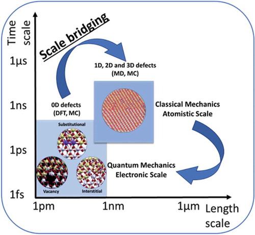
Despite all the progress in implementing disordered materials in energy applications, it is clear that a thorough understanding of the fundamental mechanisms associated with the disorder in materials is still lacking. represents the overview of the challenges (i.e. bridging the gaps between theoretical predictions and experimental observations or between techniques used at different scales) that exists for utilizing disorder for sustainable energy technologies, thereby, emphasizes the need of the development of a robust multi-scale computational framework through rigorous validation at each scale with carefully designed experiments.
Figure 5. Representation of the current challenges (i.e. bridging the gaps between models at different scales, and between theoretical predictions and experimental observations- highlighted with yellow arrows) for designing realistic materials for energy applications. The yellow box illustrate the schematic design of an aspirational high-performance energy material having non-symmetrical grains, with each grain highlighting the potential applications of materials with disorder in the sustainable energy sector. Abbreviations: MD: Molecular dynamics, DFT: Density Functional Theory, MC: Monte Carlo, TEM: Transmission Electron Microscopy, PLD: Pulse Laser Deposition, HR-STEM: High-Resolution Scanning Transmission Electron Microscopy, OER: Oxygen Evolution Reaction, ORR: Oxygen Reduction Reaction, HER: Hydrogen Evolution Reaction. The top left (computational image) is adapted with permission from K. K. Ghuman, E. Gilardi, D. Pergolesi, J. A. Kilner, T. K. Lippert, J. Phys. Chem. C 2020, DOI 10.1021/acs.jpcc.0c01797. Copyright (2020) American Chemical Society. The bottom left (experimental image) is adapted from ref [Citation37]. Song, K.; Schmid, H.; Srot, V.; Gilardi, E.; Gregori, G.; Du, K.; Maier, J. and van Aken, P. A., Cerium reduction at the interface between ceria and yttria-stabilised zirconia and implications for interfacial oxygen non-stoichiometry, APL Mater, 2, 10.1063/1.4867556, 2014; licensed under a Creative Commons Attribution (CC BY) license
![Figure 5. Representation of the current challenges (i.e. bridging the gaps between models at different scales, and between theoretical predictions and experimental observations- highlighted with yellow arrows) for designing realistic materials for energy applications. The yellow box illustrate the schematic design of an aspirational high-performance energy material having non-symmetrical grains, with each grain highlighting the potential applications of materials with disorder in the sustainable energy sector. Abbreviations: MD: Molecular dynamics, DFT: Density Functional Theory, MC: Monte Carlo, TEM: Transmission Electron Microscopy, PLD: Pulse Laser Deposition, HR-STEM: High-Resolution Scanning Transmission Electron Microscopy, OER: Oxygen Evolution Reaction, ORR: Oxygen Reduction Reaction, HER: Hydrogen Evolution Reaction. The top left (computational image) is adapted with permission from K. K. Ghuman, E. Gilardi, D. Pergolesi, J. A. Kilner, T. K. Lippert, J. Phys. Chem. C 2020, DOI 10.1021/acs.jpcc.0c01797. Copyright (2020) American Chemical Society. The bottom left (experimental image) is adapted from ref [Citation37]. Song, K.; Schmid, H.; Srot, V.; Gilardi, E.; Gregori, G.; Du, K.; Maier, J. and van Aken, P. A., Cerium reduction at the interface between ceria and yttria-stabilised zirconia and implications for interfacial oxygen non-stoichiometry, APL Mater, 2, 10.1063/1.4867556, 2014; licensed under a Creative Commons Attribution (CC BY) license](/cms/asset/b6a14188-7519-49bc-8bce-fd7b06b675a8/tapx_a_1848458_f0005_oc.jpg)
Clearly, new techniques are needed to understand the synergetic effect of multiple defects usually present in materials prepared in laboratories. Specifically, new strategies are required for understanding and manipulating disorder at the electronic level. Most of the strategies for designing realistic disordered material use atomic-level techniques such as MD and MC. However, to understand the underlying mechanisms we must find a way to use realistic material models prepared by MD/MC for electronic-level analysis via techniques such as DFT. Currently, the large sizes of the models prepared via MD/MC restrict their use in DFT simulations. The only way to understand electronic-level details of the nanometer-sized model is by analyzing a part of it at a time, which is obviously not the most robust way of analyzing materials. The development of ML techniques that enables the simulation of macroscale models with an accuracy close to DFT, in our opinion, could be one of the most promising technologies to overcome the scale bridging necessary for understanding the disordered materials at electronic scale as well as designing macroscopic materials. Finally, to make significant advances, the role of disorder in materials predicted by computational methods should be confirmed with sophisticated dynamic experimental measurements.
We hope that by highlighting the current computational methods used to design disorder in materials will inspire new opportunities for cross-disciplinary research and development of advanced tools for understanding and thereby utilizing disorder in materials for sustainable energy technologies.
Acknowledgments
The authors acknowledge the financial support from the Natural Sciences and Engineering Research Council of Canada (NSERC) Discovery grant program, [Funding Reference number RGPIN-2020-05924].
Disclosure statement
The authors declare no conflict of interest.
Additional information
Funding
References
- OECD environmental outlook to 2050: the consequences of inaction - Key facts and figures – OECD. can be found under n.d. 2012. https://www.oecd.org/env/indicators-modelling-outlooks/oecdenvironmentaloutlookto2050theconsequencesofinaction-keyfactsandfigures.html.
- Walsh MP. The importance of fuel cells to address the global warming problem. J Power Sources. 1990;29:13–28.
- Freeze JG, Kelly HR, Batista VS. Search for catalysts by inverse design: artificial intelligence, mountain climbers, and alchemists. Chem Rev. 2019;119:6595–6612.
- Wang S, Liu G, Wang L. Crystal facet engineering of photoelectrodes for photoelectrochemical water splitting. Chem Rev. 2019;119:5192–5247.
- Good P, Bamber J, Halladay K, et al. Recent progress in understanding climate thresholds. Prog Phys Geogr Earth Environ. 2018;42:24–60.
- Tanaka K, Cavalett O, Collins WJ, et al. Asserting the climate benefits of the coal-to-gas shift across temporal and spatial scales. Nat Clim Chang. 2019;9:389–396.
- Áejka J, Nachtigall P, Centi G. New catalytic materials for energy and chemistry in transition. Chem Soc Rev. 2018;47:8066–8071.
- Lee J, Urban A, Li X, et al. Unlocking the potential of cation-disordered oxides for rechargeable lithium batteries. Science. 2014;343:519–522.
- Ji H, Kitchaev DA, Lun Z, et al. Computational investigation and experimental realization of disordered high-capacity Li-Ion cathodes based on Ni redox. Chem Mater. 2019;31(7):2431–2442.
- Avila-Paredes HJ, Zhao J, Wang S, et al. Protonic conductivity of nano-structured yttria-stabilized zirconia: dependence on grain size. J Mater Chem. 2010;20:990–994.
- Jingfa D, Xiping Z, Enze M. Amorphous nickel—phosphorus alloy deposited on a support and its hydrogenation activity. Appl Catal. 1988;37:339–343.
- Li H, Li H, Dai W-L, et al., XPS studies on surface electronic characteristics of Ni-B and Ni-P amorphous alloy and its correlation to their catalytic properties, n.d.
- Brückner R. Properties and structure of vitreous silica. I. J Non Cryst Solids. 1970;5:123–175.
- Xia GG, Yin YG, Willis WS, et al. Efficient stable catalysts for low temperature carbon monoxide oxidation. J Catal. 1999;185:91–105.
- Niu K, Xu Y, Wang H, et al. A spongy nickel-organic CO 2 reduction photocatalyst for nearly 100% selective CO production, 2017.
- Hutchings GJ, Desmartin-Chomel A, Olier R, et al. Role of the product in the transformation of a catalyst to its active state. Nature. 1994;368:41–45.
- Bergmann A, Martinez-Moreno E, Teschner D, et al. Reversible amorphization and the catalytically active state of crystalline Co3O4 during oxygen evolution. Nat Commun. 2015;6:1–9.
- Hemminger JC, Sarrao J, Crabtree G, et al. Challenges at the frontiers of matter and energy: transformative opportunities for discovery science. 2015. U.S. Department of Energy, Office of Scientific and Technical Information, USA.
- Drabold DA, Estreicher SK. Theory of defects in semiconductors (Frontmatter pages). New York city (US): Springer; 2007.
- Freysoldt C, Grabowski B, Hickel T, et al. First-principles calculations for point defects in solids. Rev. Mod. Phys. 2014;86:253–305.
- Spitaler J, Estreicher SK. Perspectives on the theory of defects. Front. Mater. 2018;5:70.
- Kim J, Lee B, Kim H, et al. Redesign of Li2MP2O7 (M = Fe or Mn) by tuning the Li diffusion in rechargeable battery electrodes. Chem. Mater. 2016;28:6894–6899.
- Hu J, Xiao Y, Tang H, et al. Tuning Li-Ion diffusion in α-LiMn1-xFexPO4 nanocrystals by antisite defects and embedded β-phase for advanced Li-Ion batteries. Nano Lett. 2017;17:4934–4940.
- Heenen HH, Scheurer C, Reuter K. Implications of occupational disorder on ion mobility in Li4Ti5O12 battery materials. Nano Lett. 2017;17:3884–3888.
- Hong L, Yang K, Tang M. A mechanism of defect-enhanced phase transformation kinetics in lithium iron phosphate olivine. npj Comput. Mater. 2019;5:1–9.
- Xiong H, Yildirim H, Shevchenko EV, et al. Self-improving anode for lithium-ion batteries based on amorphous to cubic phase transition in TiO2 nanotubes. J Phys Chem C. 2012;116:3181–3187.
- Xiong H, Yildirim H, Podsiadlo P, et al. Compositional tuning of structural stability of lithiated cubic titania via a vacancy-filling mechanism under high pressure. Phys Rev Lett. 2013;110:078304.
- Rettie AJE, Lee HC, Marshall LG, et al. Combined charge carrier transport and photoelectrochemical characterization of BiVO4 single crystals: Intrinsic behavior of a complex metal oxide. J Am Chem Soc. 2013;135:11389–11396.
- Seabold JA, Zhu K, Neale NR. Efficient solar photoelectrolysis by nanoporous Mo:BiVO4 through controlled electron transport. Phys Chem Chem Phys. 2014;16:1121–1131.
- Jo WJ, Jang JW, Kong KJ, et al. Phosphate doping into monoclinic BiVO4 for enhanced photoelectrochemical water oxidation activity. Angew Chemie - Int Ed. 2012;51:3147–3151.
- Jang JW, Friedrich D, Müller S, et al. Enhancing Charge Carrier Lifetime in Metal Oxide Photoelectrodes through Mild Hydrogen Treatment. Adv Energy Mater. 2017;7. DOI:https://doi.org/10.1002/aenm.201701536.
- Yuan W, Zhang F, Wu Y, et al. Point-defect-rich carbon sheets as the high-activity catalyst toward oxygen reduction and hydrogen evolution. Catalysts. 2019;9:386.
- Fei H, Dong J, Arellano-Jiménez MJ, et al. Atomic cobalt on nitrogen-doped graphene for hydrogen generation. Nat Commun. 2015;6:1–8.
- Jung E, Shin H, Lee BH, et al. Atomic-level tuning of Co–N–C catalyst for high-performance electrochemical H2O2 production. Nat Mater. 2020;19:436–442.
- Rhodes D, Chae SH, Ribeiro-Palau R, et al. Disorder in van der Waals heterostructures of 2D materials. Nat Mater. 2019;18:541–549.
- Chen P, Zhang N, Wang S, et al. Interfacial engineering of cobalt sulfide/graphene hybrids for highly efficient ammonia electrosynthesis. Proc Natl Acad Sci U. S. A. 2019;116:6635–6640.
- Song K, Schmid H, Srot V, et al. Cerium reduction at the interface between ceria and yttria-stabilised zirconia and implications for interfacial oxygen non-stoichiometry. APL Mater. 2014;2:032104.
- Dubau L, Nelayah J, Moldovan S, et al. Defects do catalysis: CO monolayer oxidation and oxygen reduction reaction on hollow PtNi/C nanoparticles. ACS Catal. 2016;6:4673–4684.
- Polfus JM, Toyoura K, Oba F, et al. Defect chemistry of a BaZrO3 Σ3 (111) grain boundary by first principles calculations and space–charge theory. Phys Chem Chem Phys. 2012;14:12339–12346.
- Zhou LJ, Hou ZF, Wu LM, et al. First-principles studies of lithium adsorption and diffusion on graphene with grain boundaries. J Phys Chem C. 2014;118:28055–28062.
- Ferrando R, Jellinek J, Johnston RL. Nanoalloys: from theory to applications of alloy clusters and nanoparticles. Chem Rev. 2008; 108:845–910.
- Ku JH, Ryu JH, Kim SH, et al. Reversible lithium storage with high mobility at structural defects in amorphous molybdenum dioxide electrode. Adv Funct Mater. 2012;22:3658–3664.
- Kebede MA, Palaniyandy N, Ramadan RM, et al. The electrical and electrochemical properties of graphene nanoplatelets modified 75V2O5–25P2O5 glass as a promising anode material for lithium ion battery. J Alloys Compd. 2018;735:445–453.
- HONMA T, TOGASHI T, ITO N, et al. Fabrication of Na2FeP2O7 glass-ceramics for sodium ion battery. J Ceram Soc Jpn. 2012;120:344–346.
- Kang B, Ceder G. Battery materials for ultrafast charging and discharging. Nature. 2009;458:190–193.
- Baranchugov V, Markevich E, Pollak E, et al. Amorphous silicon thin films as a high capacity anodes for Li-ion batteries in ionic liquid electrolytes. Electrochem commun. 2007;9:796–800.
- Hasannaeimi V, Mukherjee S. Noble-metal based metallic glasses as highly catalytic materials for hydrogen oxidation reaction in fuel cells. Sci Rep. 2019;9:1–8.
- Kohn W, Sham LJ. Self-consistent equations including exchange and correlation effects. Phys Rev. 1965;140:A1133.
- Perdew JP, Wang Y. Accurate and simple analytic representation of the electron-gas correlation energy. Phys Rev B. 1992;45:13244–13249.
- Perdew JP, Burke K, Ernzerhof M. Generalized Gradient Approximation Made Simple. Phys. Rev. Lett. 1996;77:3865–3868.
- Parker WD, Wilkins JW, Hennig RG. Accuracy of quantum Monte Carlo methods for point defects in solids. Phys Status Solidi Basic Res. 2011;248:267–274.
- Needs RJ. Quantum Monte Carlo techniques and defects in semiconductors. Top Appl Phys. 2006;104:141–164.
- Messmer RP, Watkins GD. Linear combination of atomic orbital-molecular orbital treatment of the deep defect level in a semiconductor: nitrogen in diamond. Phys Rev Lett. 1970;25:656–659.
- Ogut, S., Kim, H. & James R., C. Ab initio cluster calculations for vacancies in bulk Si. Phys. Rev. B. 1997; 56, R11353-R11356.
- Louie SG, Schlüter M, Chelikowsky JR, et al. Self-consistent electronic states for reconstructed Si vacancy models. Phys Rev B. 1976;13:1654–1663.
- Zhang SB, Northrup JE. Chemical potential dependence of defect formation energies in GaAs: application to Ga self-diffusion. Phys. Rev. Lett. 1991;67:2339–2342.
- Van De Walle CG, Blöchl PE. First-principles calculations of hyperfine parameters. Phys Rev B. 1993;47:4244–4255.
- Fazzio A, Caldas MJ, Leite JR. Point defects in covalent semiconductors: a molecular cluster model. Int. J. Quantum Chem. 1979;16:349–361.
- Estreicher SK. Hydrogen-related defects in crystalline semiconductors: a theorist’s perspective. Mater Sci Eng R. 1995;14:319–412.
- Cartling B, Roos B, Wahlgren U. A model for self-consistent cluster calculations of the electronic structure of doped semiconductors by means of the SCF Xα scattered wave method. Chem. Phys. Lett. 1973;21:380–384.
- Cartling BG. Localized description of the electronic structure of covalent semiconductors. II. Imperfect crystals. J. Phys. C Solid State Phys. 1975;8:3183–3193.
- Ghuman KK, Hoch LB, Szymanski P, et al. Photoexcited Surface Frustrated Lewis Pairs for Heterogeneous Photocatalytic CO2 Reduction. J Am Chem Soc. 2016;138:1206–1214.
- Payne MC, Teter MP, Allan DC, et al. Iterative minimization techniques for ab initio total-energy calculations: Molecular dynamics and conjugate gradients. Rev Mod Phys. 1992;64:1045–1097.
- Leslie M, Gillian MJ. The energy and elastic dipole tensor of defects in ionic crystals calculated by the supercell method. J Physics C Solid State Phys. 1985;18:973–982.
- Makov G, Shah R, Payne M. Periodic boundary conditions in ab initio calculations. II. Brillouin-zone sampling for aperiodic systems. Phys Rev B - Condens Matter Mater Phys. 1996;53:15513–15517.
- Bruneval F, Crocombette JP. Ab initio formation volume of charged defects. Phy Rev B. 2012;86:140103.
- Varvenne C, Bruneval F, Marinica M-C, et al. Point defect modeling in materials: coupling ab initio and elasticity approaches. Phys Soc. 2013;88. DOI:https://doi.org/10.1103/PhysRevB.88.134102i.
- Nieminen RM. Supercell methods for defect calculations. Top Appl Phys. 2006;104:29–68.
- Liechtenstein AI, Anisimov VI, Zaanen J. Density-functional theory and strong interactions: orbital ordering in Mott-Hubbard insulators. Phy Rev B. 1995;52:R5467.
- Finazzi E, Di Valentin C, Pacchioni G, et al. Excess electron states in reduced bulk anatase TiO2: comparison of standard GGA, GGA+U, and hybrid DFT calculations. J Chem Phys. 2008;129:154113.
- Goyal A, Gorai P, Peng H, et al. A computational framework for automation of point defect calculations. Comput Mater Sci. 2017;130:1–9.
- Yim K, Lee J, Lee D, et al. Property database for single-element doping in ZnO obtained by automated first-principles calculations. Sci Rep. 2017;7:40907.
- Péan E, Vidal J, Jobic S, et al. Presentation of the PyDEF post-treatment Python software to compute publishable charts for defect energy formation. Chem Phys Lett. 2017;17:124–130.
- Broberg D, Medasani B, Zimmermann NER, et al. PyCDT: a Python toolkit for modeling point defects in semiconductors and insulators. Comput Phys Commun. 2018;226:165–179.
- Jain A, Ong SP, Hautier G, et al. Commentary: the materials project: a materials genome approach to accelerating materials innovation. APL Mater. 2013;1:011002.
- Yang B, Tewary VK. Green’s function-based multiscale modeling of defects in a semi-infinite silicon substrate. Int J Solids Struct. 2005;42:4722–4737.
- Koster GF, Slater JC. Wave functions for impurity levels. Phys Rev. 1954;95:1167–1176.
- Baraff GA, Schlüter M. New self-consistent approach to the electronic structure of localized defects in solids. Phys Rev B. 1979;19:4965–4979.
- Lindefelt U, Zunger A. Quasi bands in Green’s-function defect models. Phys Rev B. 1981;24:5913–5931.
- Gunnarsson O, Jepsen O, Andersen OK. Self-consistent impurity calculations in the atomic-spheres approximation. Phys Rev B. 1983;27:7144–7168.
- Puska MJ, Jepsen O, Gunnarsson O, et al. Electronic structure and positron states at vacancies in Si and GaAs. Phys. Rev. B. 1986; 34, 2695-2705.
- Korzhavyi PA, Abrikosov IA, Johansson B, et al. First-principles calculations of the vacancy formation energy in transition and noble metals. Phys Rev B - Condens Matter Mater Phys. 1999;59:11693–11703.
- Tewary VK. Multiscale Green’s-function method for modeling point defects and extended defects in anisotropic solids: application to a vacancy and free surface in copper. Phys Rev B. 2004;69: 094109-1–13.
- Chen C, Zuo Y, Ye W, et al. A critical review of machine learning of energy materials. Adv Energy Mater. 2020;10:1903242.
- Medasani B, Gamst A, Ding H, et al. Predicting defect behavior in B2 intermetallics by merging ab initio modeling and machine learning. npj Comput Mater. 2016;2:1–10.
- Dahl RE. A computer simulation study of tilt grain boundaries in gamma-iron and their interactions with point defects. Scr Metall. 1970;4:977–980.
- Dahl RE, Beeler JR, Bourquin RD. Computer simulation of extended defects in metals. Comput Phys Commun. 1971;2:301–321.
- BEELER JR Jr, DAHL RE Jr, BOURQUIN RD. Structure, energy and atom migration effects of tilt boundaries. Le J Phys Colloq. 1975;36:C4-97-C4-109.
- Cotterill RMJ, Leffers T, Lilholt H. A molecular dynamics approach to grain boundary structure and migration. Philos Mag. 1974;30:265–275.
- Holm EA, Olmsted DL, Foiles SM. Comparing grain boundary energies in face-centered cubic metals: al, Au, Cu and Ni. Scr Mater. 2010;63:905–908.
- Echeverri Restrepo S, Thijsse BJ, in Mater. Res. Soc. Symp. Proc., Cambridge University Press, 2010, pp. 137–142.
- von Alfthan S, Benedek NA, Chen L, et al. The structure of grain boundaries in strontium titanate: theory, simulation, and electron microscopy. Annu Rev Mater Res. 2010;40:557–599.
- Chua ALS, Benedek NA, Chen L, et al. A genetic algorithm for predicting the structures of interfaces in multicomponent systems. Nat Mater. 2010;9:418–422.
- Piana S, Gale JD. Understanding the barriers to crystal growth: dynamical simulation of the dissolution and growth of urea from aqueous solution. J. Am. Chem. Soc. 2005;127:1975–1982.
- Hamad S, Cristol S, Catlow CRA. Simulation of the embryonic stage of ZnS formation from aqueous solution. J. Am. Chem. Soc. 2005;127:2580–2590.
- Sayle DC, Maicaneanu SA, Slater B, et al. Exercising control over the influence of the lattice misfit on the structure of oxide–oxide thin film interfaces. J Mater Chem. 1999;9:2779–2787.
- Sayle TXT, Catlow CRA, Maphanga RR, et al. Generating MnO2 nanoparticles using simulated amorphization and recrystallization. J Am Chem Soc. 2005;127:12828–12837.
- Sayle TXT, Catlow CRA, Sayle DC, et al. Computer simulation of thin film heteroepitaxial ceramic interfaces using a near-coincidence-site lattice theory. Philos Mag A Phys Condens Matter, Struct Defects Mech Prop. 1993;68:565–573.
- Sayle DC, Sayle TXT, Parker SC, et al. The stability of defects in the ceramic interfaces, and. Surf Sci. 1995;334:170–178.
- Fisher CAJ, Matsubara *H. Philos Mag. Molecular dynamics simulations of interfaces between NiO and cubic ZrO2. 2005;85:1067–1088.
- Ghuman KK, Gilardi E, Pergolesi D, et al. Microstructural and Electronic Properties of YSZ/CeO2 Interface via Multiscale Modelling. J Phys Chem C. 2020. DOI:https://doi.org/10.1021/acs.jpcc.0c01797
- Sadigh B, Erhart P, Stukowski A, et al. Scalable parallel Monte Carlo algorithm for atomistic simulations of precipitation in alloys. Phys Rev B - Condens Matter Mater Phys. 2012;85:184203.
- Romero C, Noyola J, Santiago U, et al. A new approach to the computer modeling of amorphous nanoporous structures of semiconducting and metallic materials: a review. Materials (Basel). 2010;3:467–502.
- Huber L, Hadian R, Grabowski B, et al. A machine learning approach to model solute grain boundary segregation. npj Comput Mater. 2018;4:1–8.
- Snow BD, Doty DD, Johnson OK. A simple approach to atomic structure characterization for machine learning of grain boundary structure-property models. Front Mater. 2019;6:120.
- Wu X, Wang Y, He K, et al. Application of machine learning to predict grain boundary embrittlement in metals by combining bonding-breaking and atomic size effects. Materials (Basel). 2020;13:179.
- Echeverri Restrepo S, Tamayo Giraldo S, Thijsse BJ. Using artificial neural networks to predict grain boundary energies. Comput Mater Sci. 2014;86:170–173.
- Stachurski ZH. On structure and properties of amorphous materials. Materials (Basel). 2011;4:1564–1598.
- (Anthony) Kelly A, Groves GW. Crystallography and crystal defects. Harlow Essex: Longmans; 1970.
- Car R, Parrinello M. Structural, dynamical, and electronic properties of amorphous silicon: An ab initio molecular-dynamics study. Phys Rev Lett. 1988;60:204–207.
- Kaur K, Prakash S, Goyal N, et al. Structure factor of amorphous TiO2 nanoparticle; Molecular Dynamics Study. J Non Cryst Solids. 2011;357:3399–3404.
- Kaur K, Prakash S, Goyal N. Strained structure of differently prepared amorphous TiO2 nanoparticle: Molecular dynamics study. J Mater Res. 2011;26:2604–2611.
- Rino J, Studart N. Structural correlations in titanium dioxide. Phys Rev B - Condens Matter Mater Phys. 1999;59:6643–6649.
- Cai B, Drabold DA. Properties of amorphous GaN from first-principles simulations. Phys Rev B - Condens Matter Mater Phys. 2011;84:075216.
- Kaur K, Singh CV, 2012.
- Ghuman K, Singh CV. Effect of doping on electronic structure and photocatalytic behavior of amorphous TiO2. J Phys Condens Matter. 2013;25:475501–475512.
- Ghuman KK. Mechanistic insights into water adsorption and dissociation on amorphous -based catalysts. Sci Technol Adv Mater. 2018;19:44–52.
- Ghuman KK, Singh CV. Self-trapped charge carriers in defected amorphous TiO2. J Phys Chem C. 2016;120:27910–27916.
- Li C, Wang T, Zhao ZJ, et al. Angew Chemie - Int Ed. Promoted Fixation of Molecular Nitrogen with Surface Oxygen Vacancies on Plasmon-Enhanced TiO2 Photoelectrodes. 2018;57:5278–5282.
- Valladares AA. Glas. mater. res. prog. Wolf JC, Lange L, Eds. New York: Nova Science Publishers, Inc.; 2008. p. 61–123.
- Mata-Pinzón Z, Valladares AA, Valladares RM, et al. Superconductivity in bismuth. A new look at an old problem. PLoS One. 2016;11. DOI:https://doi.org/10.1371/journal.pone.0147645.
- Rodríguez I, Valladares RM, Hinojosa-Romero D, et al. Emergence of magnetism in bulk amorphous palladium. Phys Rev B. 2019;100:024422.
- De Tafen DN, Drabold A. Realistic models of binary glasses from models of tetrahedral amorphous semiconductors. Phys Rev B - Condens Matter Mater Phys. 2003;68:165208.
- McGreevy RL. Reverse Monte Carlo modelling. J Phys Condens Matter. 2001;13:R877–R913.
- Playford H, Keen D, Tucker M. Local structure of crystalline and amorphous materials using reverse Monte Carlo methods. Neutron News. 2016;27:17–21.
- Biswas P, Atta-Fynn R, Drabold DA. Reverse Monte Carlo modeling of amorphous silicon. Phys Rev B - Condens Matter Mater Phys. 2004;69:195207.
- Deringer VL, Bernstein N, Bartók AP, et al. Realistic atomistic structure of amorphous silicon from machine-learning-driven molecular dynamics. J. Phys. Chem. Lett. 2018;9:2879–2885.
- Behler J, Parrinello M. Generalized neural-network representation of high-dimensional potential-energy surfaces. Phys Rev Lett. 2007;98:146401.
- Bartók AP, De S, Poelking C, et al. Machine learning unifies the modeling of materials and molecules. Sci Adv. 2017;3:e1701816.
- Bartók AP, Payne MC, Kondor R, et al. Gaussian approximation potentials: the accuracy of quantum mechanics, without the electrons. Phys Rev Lett. 2010;104:136403.
- Shapeev AV. Moment tensor potentials: a class of systematically improvable interatomic potentials. Multiscale Model. Simul. 2016;14:1153–1173.
- Smith JS, Isayev O, Roitberg AE. ANI-1: an extensible neural network potential with DFT accuracy at force field computational cost. Chem Sci. 2017;8:3192–3203.
- Deringer VL, Csányi G. Machine learning based interatomic potential for amorphous carbon. Phys Rev B. 2017;95:094203.
- Bartók AP, Kondor R, Csányi G. On representing chemical environments. Phys Rev B - Condens Matter Mater Phys. 2013;87:184115.
- Artrith N, Urban A, Ceder G. Constructing first-principles phase diagrams of amorphous LixSi using machine-learning-assisted sampling with an evolutionary algorithm. J Chem Phys. 2018;148:241711.
- Onat B, Cubuk ED, Malone BD, et al. Implanted neural network potentials: application to Li-Si alloys. Phys Rev B. 2018;97:094106.