
Abstract
Determining how deep instruments can be inserted into the femoral canal without touching adjacent structures is a fundamental necessity for navigating instruments in primary and revision total hip arthroplasty. The aim of the study was to determine the reachable depth of a straight instrument inserted into the femur canal during primary and revision total hip arthroplasty. Based on the three-dimensional data of twenty-six femurs, obtained from a CT scan, the insertion depth of a virtual, straight instrument was accessed by a simulation. The effect of the diameter of the virtual instrument and the extension of the osteotomy were evaluated. Without extending the osteotomy, 100% of the femoral canal was reachable to a depth of 5.1–6.3 cm for instruments with a diameter of 10 mm. The depth was measured from the lower edge of the osteotomy. A maximum lateral extension of the osteotomy by 1 cm enlarges the access to a depth of 8.8 cm. The results provide a theoretical basis for the limitations of guiding instruments used for the preparation of the femoral canal. Bone preserving methods need the development of angulated instruments to reach deep areas in the femoral canal.
Introduction
Removing bone, during primary and revision total hip arthroplasty (THA), or cement, in revision THA, is a fundamental necessity in the preparation of the femoral canal, while preserving as much bone stock as possible.[Citation1,Citation2] These tasks are usually performed by tools such as broaches, reamers, and chisels or more technically sophisticated high-speed bone burrs or ultrasound probes.[Citation3,Citation4] Removal of the femoral bone cement in revision total hip arthroplasty with a high-powered drill or burr potentially has a risk of damage to the bone, resulting in perforation and fracture of the femur.[Citation5] Instruments used in surgery which rotate or vibrate at a high frequency can produce potentially environmental and body contamination risks.[Citation6,Citation7]
The combination of navigation and machine-guided tools should allow us to perform these tasks more efficiently and precisely. Earlier attempts to introduce this technology into the field of orthopaedics have failed because no benefit was provided to the patient and several complications related to the surgical technique were reported.[Citation8–11] Robotic-assisted technology had advantages in terms of preoperative planning and the accuracy of the intraoperative procedure.[Citation11] Also navigation has seen a lot of development during the past decade and robotic devices are getting more and more attention.[Citation12–16] If this technology, which is a current standard in industrial production and mechanical engineering [Citation17] is adapted to minimally invasive approaches to the hip, it will not only be possible to perform current procedures faster and with high precision but it will also be possible to cut shapes that had not been possible in the past. Looking at the femoral canal, the use of such a technology would allow us to remove a volume of bone, cement of fibrous tissue from the femoral canal in any technically possible shape based on a preoperative scan of the bone and a precise three-dimensional plan of the work volume. Before implementing industrial computer-based cutting technology into orthopedic surgery, there are still many problems to be solved. One challenge is to guide instruments, which can reach deep layers of the femoral canal considering the inner anatomy by using a minimally invasive approach. The femur typically has an anterior – posterior and medial – lateral curve.[Citation18,Citation19] The standard robotic systems consist of a kinematic chain composed of several rigid links which are connected by direct driven rotational joints. A freely positionable straight cutting tool, typically a high-speed cutter, can be mounted as end effector. Straight tools have certain limits, when used in a 3D curved cavity. They are only able to reach specific areas in a given depth, depending on the size and shape of the canal, its proximal opening as well as the kinematic constraints of the robotic system. Motions of a robotic device are highly constrained by the cavity walls. Computing interference-free insertion paths in which a peg (the moving body) is to be inserted without interferences into a hole (the fixed cavity) is a well-known problem studied in robotics and it is referred to as the “peg-in-hole” problem.[Citation20] Insertability analysis is required in biomedical engineering to validate shape designs, identify interferences, blocking surfaces, and stuck configurations, make shape modifications, and explore shape alternatives, when inserting a prosthetic implant.[Citation20] In the simulation described here, the movement of a straight instrument is simulated in different femurs and the working volume is quantified by calculating the reachable areas and depths, when varying the cavity walls.
The aim of the study was to determine the maximum reachable depth of a straight instrument by considering the osteotomy level and the anatomy of the femur canal and to determine the effect on the depth when extending the osteotomy level laterally.
Material and methods
The data used for the simulation were collected from 26 chemically macerated femurs. The macerated femurs were donated anonymously out of a population of Caucasians of an age above 40 years. The bones were cleaned from soft tissue by submerging them in a maceration liquid composed of a 5–10% solution of pure sodium hydrochlorite and rinsing under hot water several times. After the maceration, the femurs were bleached in 2% hydrogen peroxide solution.
Fifteen of the 26 femurs were from the right side and 11 were from the left side. All femurs were classified according to the canal flare index (CFI) and the centrum collum diaphysis (CCD) angle.[Citation18,Citation21] Three femurs had a CFI below 3, corresponding to a champagne flute shape of the femoral canal, and one femur had a stovepipe shape with a CFI higher than 4.7. Measuring the CCD-angle, eight femurs were classified as coxa vara with a CCD-angle lower than 120°. All other femurs ranged from 120° to 140°, and were therefore classified as coxa norma. The average femoral length was 45.1 ± 2.7 cm, measured from the highest point of the femoral head to the epicondyle cleft. The average femoral head size was 47 ± 4 mm.
Images from the femurs were taken with a computed tomography (CT) scanner (Light Speed 16, GE Medical Systems, Herts, UK) in helical mode ().
Table 1. Settings of the computer tomography scan.
3D models were generated from the images obtained by the CT-Scanner, using Mimics rendering software (Materialise®, V14, Leuven, Belgium). In order to discriminate the spongious bone, which can be extracted, from the cortical bone, two selection masks were generated from the raw images, using ranges of gray values (). Based on the 3D models, the osteotomy was planned for every bone by drawing a line from the greater trochanter to a point at a perpendicular distance of 1 cm from the lesser trochanter. A virtual osteotomy was performed in a 45° angle which divided the model along the planned line from anterior to posterior (). All osteotomies were observed by an experienced orthopedic surgeon (M. N.).
Figure 1. (A) Transversal view of the proximal part of a femur obtained by a CT scan. The lower half shows the selection masks for spongious (black) and cortical bone (light grey). (B) 3D model of the femur, showing the planed osteotomy in 45°. (C) Frontal view of the femur with removed femoral head. Working principle of the simulation program: The dashed lines show two possible configurations of the virtual instrument entering from the osteotomy into the femoral canal. The dark grey area was not considered in the simulation.
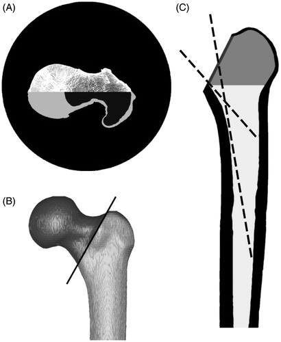
After the removal of the femoral head, the resulting section of the osteotomy defined the entrance surface for the virtual instrument (). The volume between the greater and lesser trochanter (, shaded area) was not considered in the simulation, since this volume is directly accessible through the osteotomy. The remaining part, particularly the femoral canal, was imported to Matlab (Matlab®, V7, The Mathworks, Natick, MA). An algorithm was written that simulates the access of a freely movable virtual instrument to the femoral canal. shows a two-dimensional visualization of the axis of the instrument in two different configurations. Virtual instruments with the defined diameter from 1 to 10 mm, corresponding to existing instruments, were simulated. The length of the instrument was not limited for the simulation. A three-dimensional linear equation was used to describe the path of the virtual instrument from a point of the section of the osteotomy to any point
inside the femoral canal
For every point along this path, described by the vector , the algorithm checked if the virtual instrument collided with the inner walls of the femoral canal or if it passed through a previously inaccessible volume. If a collision occurred, the actual voxel was marked as inaccessible. The simulation started at the first, most superior layer, and moved into the femoral canal. For every layer, the simulation tried to reach every voxel without a collision.
Starting with the entrance section given by the osteotomy described above, the osteotomy was gradually extended laterally, in order to gain deeper access to the femoral canal. The osteotomy was extended in steps of 2.5 mm to a maximum extension of 10 mm.
The ultimate accessible depth, the depth at which 100% of the layer was accessible and the depths for intermediate steps in 10% intervals were determined after the simulation. For direct comparison of the results, the values were normalized to the mean length of the bones. Each depth determined for each bone was multiplied by the length of the femur and then divided by the mean length of all femura in order to get comparable results.
Statistical analysis was carried out with SPSS 17 (SPSS Inc., Chicago, IL). To test which depths could be reached with instruments of various diameters, the one-way ANOVA was used for global effects while the Games–Howell procedure was used for pair-wise comparison of the diameters regarding the reached depths. Homogenous sub-groups were calculated based on the pair-wise Scheffé procedure. To calculate the influence of possible extensions of the access portal, a repeated-measures ANOVA was used to determine the within-subject effects. The Sidak procedure was used for pair-wise comparison of the four different extensions.
Results
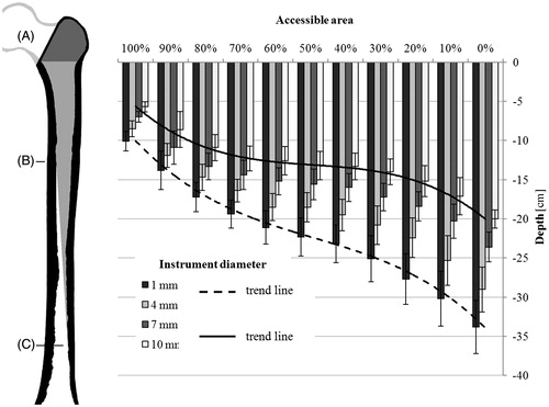
The reachable depth, where 100% of the area could be reached, was determined for all bones when varying the diameters of the instrument and extending the osteotomy. On an average, the ultimate depth (, position C), which could be reached by the virtual instrument was 33.9 ± 3.4 cm for an instrument diameter of 1 mm. For an instrument with a diameter of 10 mm, the ultimate depth was 20.0 ± 1.2 cm, counted from the lower edge of the osteotomy section (, position A). The average depth at which 100% of a cross section of the femoral canal could be reached (, position B) was 10.1 ± 1.2 cm and 5.7 ± 0.7 cm, respectively.
Figure 2. Reachable depths in correlation to the accessible area of a cross section. The reachable depths and standard deviations of instruments with 1, 4, 7, and 10 mm diameter are shown. The size of the femur (left) is adjusted to the scale of the graph (right). Accessible volume in the femoral canal marked in light gray. From the osteotomy (A) down to position B, 100% of the femoral canal is accessible. Between positions B and C, the accessible area decreases from 100% to 0%.
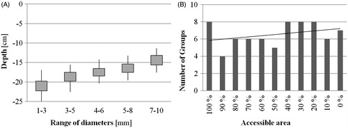
Homogeneous sub-groups for the instrument’s diameter were calculated. A change of the diameter by ±1–2 mm had no significant influence at the reachable depth. For example, shows the homogeneous sub-groups that were calculated for the depths where 50% of the section of the femoral canal could be reached. The number of different instrument diameters grouped in one homogeneous sub-group depended on the size of the area that was accessible. With decreasing size of the accessible area (synonymous with an increasing depth), the number of the groups increased ().
Figure 3. (A) Homogeneous sub-groups for the depths and standard deviation where 50% of the section of the femoral canal could be reached. (B) Number of homogeneous sub-groups in relation to the accessible area. The black line indicates the trend of the numbers regarding the accessible area.
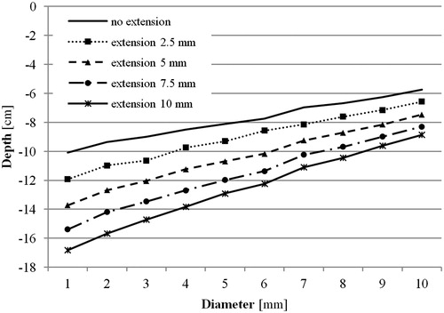
A lateral extension of the osteotomy allowed the instrument to reach deeper into the femoral canal (). An extension of 2.5 mm enabled a significant deeper access (p ≤ 0.001), independent of the diameter of the instrument. The effect of the extension also depended on the diameter of the instrument (). A virtual instrument with a diameter of 1 mm, an extension of 10 mm of the osteotomy increased the depth, where 100% of the cross section of the femoral canal could be accessed, by 6.7 ± 1.2 cm. For instruments with a diameter of 10 mm, the same extension enabled a 3.0 ± 0.7 cm deeper access.
Figure 4. Influence of the lateral extension of the osteotomy on reachable depths where 100% of the cross section of the femoral canal could be reached.
Discussion
For primary and revision total hip arthroplasty usually, a straight milling instrument is inserted in the femoral canal to extract bone, cement, and interfacial connective tissue. Due to the shape of the femur and the geometry of the instrument, only a limited volume can be accessed directly through the osteotomy. The choice of the instrument’s diameter and a lateral extension of the osteotomy can give the surgeon access to a larger volume of the femoral canal.
The interference-free insertion of a solid body into a cavity is a well-known problem in robotics and was described in several studies.[Citation20] This study aimed to vary the constraints and investigate about the effects of increasing the insertion area at the osteotomy level.
Our results show that it is possible to access 100% of a cross section in the femoral canal to a depth of 10.1 ± 1.2 cm using an instrument with 1 mm diameter. As expected, the reachable depth decreases with thicker instruments. For instruments with a diameter of 10 mm, the minimum depth was 5.7 ± 0.7 cm. For smaller accessible areas of the cross section, the calculated depths increase to an ultimate depth of 33.9 ± 3.4 cm for an instrument with 1 mm diameter. The increase of the depth shows a non-linear trend (), indicating that the depths change rapidly in the beginning and ending of the reachable volume. In the middle region, the depth for the accessible cross sections between 70% and 30% increases slowly. This slow increase of depth, equivalent to the rapid change of the accessible cross section within a short distance, is caused by the curved geometry of the femur, partially obstructing the access to deeper areas. shows that the rate, at which the depth increases, depends on the diameter of the instruments. Whereas the increase is almost linear for instruments with a diameter of 1 mm, its curved trend is more pronounced for larger diameters. This indicates that the curved geometry of the femur has a smaller influence on instruments with a small diameter, since the obstructing geometry can be bypassed to a certain extend by varying the orientation of the instruments. Instruments with larger diameters get easily stuck due to the restricted space inside the femoral canal.
Since the complete extraction of interfacial connective tissue or bone cement is vital for a successful revision, the depth until where 100% of a cross section can be accessed is of utmost relevance. Considering the length of 8.6–14.5 cm for an average cementless prosthesis (Accolade Series, Stryker, Mahwah, NJ) or of 10–13.5 cm cemented prosthesis and an additional space for bone cement (ABG II Series, Stryker, Mahwah, NJ), it can be assumed that in most cases a revision cannot be accomplished without extending the osteotomy, windowing the femur or using a special angulated instrument. In many revision cases the anatomy of the femur can be distorted from canal remodeling, osteolysis, fractures, etc., which makes it difficult to plan the procedure preoperatively.
The results show that a small lateral extension of the osteotomy by 2.5 mm already has a significant influence (p ≤ 0.001) on the reachable depth where 100% of a cross section can be accessed for all calculated diameters. Obviously, the reachable depths increase with larger extensions. As shows, the additional depth is not only proportional to the size of the extension but also to the diameter of the instrument. At the same maximum extension of 10 mm, an instrument with a diameter of 1 mm allows a 1.7 times deeper access, whereas an instrument with a diameter of 10 mm only a 1.5 times deeper access is possible. The dependence on the diameter can probably be explained by small indents of the cortical bone tissue that cannot be accessed by instruments with larger diameters and, therefore narrowing the accessible area.
In addition to the effect of differently sized instruments, the study reveals the occurrence of homogeneous sub-groups of instrument’s diameters, where the change of the diameter by ±1–2 mm has no significant influence on the reachable depth. The trend of the number of groups per accessible area () suggests that at deeper areas the influence of the diameter is larger, due to the fact of a thinner volume of the femoral canal. The counterintuitive high number of sub-groups for the area were 100% of a cross section can be accessed, might be explained by the lager occurrence of small indents near the femoral head due to the more complex structure of the cortical bone tissue. Nevertheless, the occurrence of sub-groups implies that it is not necessary for instruments in 1 mm increments. A set of instruments corresponding to the mean diameter of these sub-groups should be sufficient.
Although this study shows results, which were also experienced by surgeons, the small sample size is one of the major limitations of this study. The high variability of the femur shape requires a larger number of samples for reliable conclusions. The results in this paper, therefore, have only a relative validity; nevertheless, they are a first basis to argue. A further limitation is that small variations in the geometry of the femur can limit the accessible depth. This means that in the simulation small indents of cortical bone tissue are inaccessible for the milling instruments with larger diameters, and therefore additionally narrowing the accessible area. In a real setting these indents are probably leveled by the milling instrument. Although the data were pre-processed in order to reduce those artifacts, a possible influence on the accessible depth, especially for larger instruments, has to be considered. Gender, age, as well as body mass index, were not available for the anatomic specimens.
We tested the theoretical accessibility of the femoral canal with a straight instrument. The results show that it is not possible to directly access the volume necessary for primary or revision surgery, without extending the osteotomy, which reflects well the surgical experience. Nevertheless, to ensure a comparable result in surgery the instrument would have to be positioned precisely. Since the manual positioning of instruments in the femoral canal has its limitations, especially due to the lack of a direct visual control, the combination of navigation and a machine-guided tool could provide this precision.
With this simulation, it is possible to provide a path estimation of the instruments used intraoperativley, considering their size and possible movements. The necessity of increasing the opening to the femoral canal lateral at the osteotomy level can be evaluated preoperatively. This additional information can be helpful in the planning process of difficult revision cases with abnormal anatomies of the femur and for optimizing instruments which are inserted into the femoral canal during surgery. The program could improve current planning software based on CT-scans by adding a simulation module for the specific instruments used during surgery.
Subsequent studies will include a larger database of femurs and address the effect of an angulated geometry of the instrument as well as the feasibility of automation. Although it is more difficult to navigate with an angulated instrument in the restricted volume of the femoral canal, the accessible volume could be greater than with straight instruments. A more detailed analysis of an angulated instrument and a calculation of an optimal geometry could provide significant results. It can be assumed that there is a correlation between the insertion depth and patient characteristics like height of the femur, the femoral canal size, the femur cortex thickness, and the various femoral shape characteristics. The results show that it might be too general and restrictive to follow one insertion strategy for all patients. Increasing the femoral canal opening increases insertability of long instruments. However, there is a certain limit given in length and diameter of the instrument. In this case, windowing of the femur will be required to reach deeper areas. Especially, with deformed bones, special instrumentation is needed for extracting implants during a revision case. By adding large datasets and by taking into account statistical shape models, implants and instruments can be designed for the specific needs of different classes of patients.
Summarizing the results supports common knowledge of hip surgeons that it is not possible to directly access the volume necessary for primary or revision surgery with a straight instrument, without extending the osteotomy laterally. Quantification on how deep a straight instrument can be inserted into the femoral canal can be determined by performing a CT-based preoperative plan and by performing a computer based simulation. Bone preserving methods should take into account to use angulated instruments to reach deeper areas in the femoral canal.
Acknowledgements
This study was supported by Mag. rer. nat. Dennis Huber, scientific collaborators and Barbara Kuhlmann, medical student.
Disclosure statement
No funds of any company were received for this study. No commercial sponsor was involved in any way in the design of the study, and the collection, analysis and interpretation of data. The same is true for the writing of the manuscript and the decision for publication. The study was funded by Experimental Orthopaedics, Department of Orthopaedic Surgery, at the Medical University Innsbruck. The following conflicts of interests are relevant to the article: M. Nogler is a consultant for Stryker IMT, J. L. Moctezuma is an employee of Stryker IMT. There are no other conflicts of interest to declare.
References
- Fletcher M, Jennings GJ, Warren PJ. Ultrasonically driven instruments in the transfemoral approach – an aid to preservation of bone stock and reduction of implant length. Arch Orthop Trauma Surg. 2000;120:559–561.
- Laing A, Mullett H, Curtin W. Segmental femoral cement extraction at revision hip arthroplasty – a safe technique. Eur J Orthop Surg Traumatol. 2002;12:132–136.
- Nogler M, Krismer M, Hozack WJ, et al. A double offset broach handle for preparation of the femoral cavity in minimally invasive direct anterior total hip arthroplasty. J Arthroplasty. 2006;21:1206–1208.
- Schmidt J, Nordmann K. Removal of bone cement from the femoral canal using an acoustic emission-controlled milling device. Med Biol Eng Comput. 1994;32:258–260.
- Akiyama H, Kawanabe K, Goto K, et al. Computer-assisted fluoroscopic navigation system for removal of distal femoral bone cement in revision total hip arthroplasty. J Arthroplasty. 2007;22:445–448.
- Nogler M, Lass-Florl C, Ogon M, et al. Environmental and body contamination through aerosols produced by high-speed cutters in lumbar spine surgery. Spine. 2001;26:2156–2159.
- Nogler M, Lass-Florl C, Wimmer C, et al. Contamination during removal of cement in revision hip arthroplasty. A cadaver study using ultrasound and high-speed cutters. J Bone Joint Surg, Br Vol. 2003;85:436–439.
- Schulz AP, Seide K, Queitsch C, et al. Results of total hip replacement using the Robodoc surgical assistant system: clinical outcome and evaluation of complications for 97 procedures. The International Journal of Medical Robotics + Computer Assisted Surgery: MRCAS. 2007;3:301–306.
- Nogler M, Polikeit A, Wimmer C, et al. Primary stability of a robodoc implanted anatomical stem versus manual implantation. Clin Biomech. 2004;19:123–129.
- Prymka M, Hassenpflug J. Clinical outcome, 6 years after robot assisted hip endoprostheses implantation – a prospective study. Z Orthopadi Unfallch. 2009;147:675–682.
- Honl M, Dierk O, Gauck C, et al. Comparison of robotic-assisted and manual implantation of a primary total hip replacement. A prospective study. J Bone Joint Surg Am Vol. 2003;85-A(8):1470–1478.
- Wolf A, Shoham M. Medical automation and robotics. In: Nof SY, editor. Springer handbook of automation. Berlin, Heidelberg: Springer; 2009. p. 1397–1407.
- Guthart GS, Salisbury JK Jr, editors. The IntuitiveTM telesurgery system: overview and application. 2000 Proceedings ICRA '00 IEEE International Conference on Robotics and Automation; 2000.
- Kazanzides P, Fichtinger G, Hager GD, et al. Surgical and interventional robotics: core concepts, technology, and design. IEEE Robot Autom Mag/IEEE Robot Autom Soc. 2008;15:122–130.
- Banks SA. Haptic robotics enable a systems approach to design of a minimally invasive modular knee arthroplasty. Am J Orthop. 2009;38:23–27.
- Taylor RH, Stoianovici D. Medical robotics in computer-integrated surgery. IEEE Trans Robot Automat. 2003;19:765–781.
- Pan ZX, Zhang H, Zhu ZQ, et al. Chatter analysis of robotic machining process. J Mater Process Technol. 2006;173:301–309.
- Noble PC, Alexander JW, Lindahl LJ, et al. The anatomic basis of femoral component design. Clin Orthop Relat Res. 1988:148–165.
- Noble PC, Box GG, Kamaric E, et al. The effect of aging on the shape of the proximal femur. Clin Orthop Relat Res. 1995:31–44.
- Joskowicz L, Taylor RH. Interference-free insertion of a solid body into a cavity: an algorithm and a medical application. Int J Robot Res. 1996;15:211–229.
- Tawada K, Iguchi H, Tanaka N, et al. editors. A908. Measurement of the canal flare index using 3-D models and the effect of the rotational femur position. J Bone Joint Surg, Br Vol. 2011;93(Suppl IV):475.