
Abstract
Background: Minimally invasive surgery (MIS) based on computer and robot-assisted technology is becoming more and more popular.
Methods: Intuitive motion control implemented by kinematic algorithm of the slave manipulator based on the 3D Display (DD) is proposed to eliminate absonant hand-eye coordination, kinematic dissimilarity and workspace mismatch of the master-slave manipulator and is applied in the novel minimally invasive surgical (MIS) robot developed in our lab. Forward and inverse kinematics of MIS robot are analyzed based on the screw theory. The kinematic algorithm of MIS robot based on the DD is achieved.
Results: The trajectory tracking results that the movement trends between the master and slave manipulators consistently validate the effectiveness of forward and inverse kinematics. The simulation results of the kinematic algorithm by virtue of Simulink and SimMechanics sub-modules of the MATLAB and intuitive control experiment that the root mean square error of cumulative position increments is less than 0.5 mm validate effectiveness of intuitive control algorithm.
Conclusion: Successful animal experiments furthermore validate the effectiveness of intuitive control algorithm.
Introduction
With the advantages of less trauma, few postoperative disease, quick rehabilitation and so on, at the same time, with the development of the computer and robot-assist technology, minimally invasive surgery (MIS) has made rapid progress and is becoming more and more popular. There are two successful compute and robot-assisted MIS systems, Da Vinci system and Zeus system.[Citation1,Citation2] The Raven system is a compact and lightweight robot and designed for military use in the University of Washington.[Citation3,Citation4] The DLR MIRO system is designed to achieve a high degree of versatility and allows for bimanual endoscopic tele-surgery with force feedback.[Citation5] Bogue [Citation6] designed the “Surgeon’s Operating Force-feedback Interface Eindhoven” robot called Sofie integrating force feedback. Berkelman and Ma [Citation7] designed a smaller, simpler, modular and tele-operated robotic systems for MIS.
The improvement of computer and robot-assist technology is not only to improve the robotic structure and function but also design better kinematic control algorithm for the slave manipulator to accomplish surgical operation with preferably comfortable operation posture for surgeon. Stefanie Speidel et al. [Citation8] proposed a method to tracking the instrument trajectory in the operation by virtue of endoscopic image sequences, these image information can be applied for surgical gesture interpretation. Weede et al. [Citation9,Citation10] presented an endoscopic navigation for MIS, which predicted instruments for autonomous guidance of the endoscopic camera based on the knowledge extracted by trajectory clustering, maximum likelihood classification and a Markoy model. Reiley et al. [Citation11] have used statistical modeling for capturing variability. Wei et al. [Citation12] proposed a visual tracking method for stereo endoscopy with robustness, simplicity and working frequency being 7 Hz. Staub et al. [Citation13] proposed a method based on kinematic pose prediction and image analysis to track surgical instruments. A filtering method proposed by Stephen is utilized to estimate the shape and end effector pose of snake robot.[Citation14]
Intuitive control realized by kinematic algorithm of the slave manipulator based on DD is proposed for the endoscopic and instrument manipulator to be suitable for doctor’s habits; it can eliminate absonant hand-eye coordination, kinematic dissimilarity and workspace mismatch of master-slave manipulator.
Methods
The overview of MIS robotic system
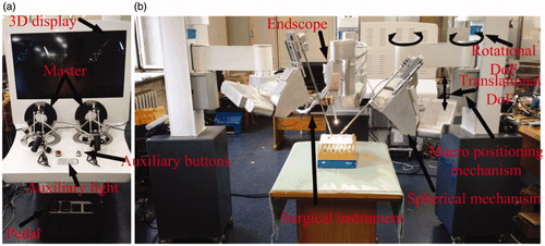
The robotic system designed for holding surgical instrument and endoscopy for surgical operation in abdominal MIS is shown in . The robotic system comprises three parts: the master console, the slave device and the surgical instrument. The master console is composed of two 7-degrees-of-freedom master manipulators produced in force dimension that are applied to control three slave manipulators to accomplish surgical operation, four pedals used to switch between various functions, control box, 3D monitor, auxiliary lights and auxiliary buttons. The slave device contains three manipulators, each slave manipulator comprises of macro and micro positioning mechanisms. Macro positioning mechanism adopts SCARA configuration with one translational degree of freedom (DoF) and two rotational DoFs. Micro mechanism is applied to realize remote center motion (RCM). The two slave robotic manipulators are used to hold clamps, forceps, scissors, needle holders and so on. The other robotic arm is utilized to grip endoscopy to collect image of the surgical area and send to the monitor for 3D display.
Figure 1. An overview of MIS robotic system: (a) Master console; (b) Slave manipulator.
Forward kinematics of the slave manipulator
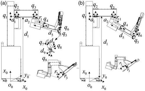
Each manipulator for holding the surgical instrument consists of the passive part with three DoFs (q1, q2, q3) and the active part with six DOFs (q4, q5, q6, q7, q8, q9). The base coordinate S is mounted on the bottom of the table to calculate the position and posture (PAP) of manipulator for holding endoscopy or surgical instrument. The initial configuration of the slave manipulator is depicted in .
Figure 2. The initial configuration of the manipulator: (a) The manipulator holds surgical instrument; (b) The manipulator holds endoscopy.
To construct the twists for the revolute joints and prismatic joints relative to the base frame S for the manipulator holding surgical instrument, we have
(1)
where s1 = sin(β1), c1 = cos(β1), s2 = sin(β2), c2 = cos(β2), s3 = sin(β3), c3 = cos(β3).
To construct the twists for the revolute and prismatic joints relative to the base frame S for the manipulator holding endoscopy, consider
(2)
where s11 = sin(β11), c1 = cos(β11), s2 = sin(β2), c2 = cos(β2), s3 = sin(β3), c3 = cos(β3).
The axis points for the manipulator holding surgical instrument are chosen as
(3)
and the axis points for the manipulator holding endoscopy are chosen as
(4)
This yields twists for a revolute joint
(5)
and twists for a prismatic joint
(6)
and the zero configuration of the manipulators holding surgical instrument and endoscopy are given by
(7)
The forward kinematic map of the manipulator holding surgical instrument and endoscopy have the forms
(8)
Inverse kinematics of manipulator
The inverse kinematic problem is that the corresponding joint angles are calculated to achieve a desired configuration for the tool.
Inverse kinematics of the manipulator holding surgical instrument
The active part of the manipulator comprises of one prismatic joint and five revolute joints. The RCM mechanism with first three joints (q4, q5, q6) is used to achieve the position control of the end-effector depicted in . The surgical instrument with three joints (q7, q8, q9) is applied to accomplish the posture control of the forceps shown in .
Based on EquationEquation (8)(8) , EquationEquation (9)
(9) can be obtained as follows:
(9)
First, a point p8, which is the intersection point of the axes of the q6, q7, q8 joints is applied to both sides of EquationEquation (9)(9) ; second, a point p4, which is the intersection point of the axes of the q4 and q5 joints is subtracted from both sides, last, taking the modulus of both sides of equation yields
(10)
q9 can be obtained.
Since q9 is known, EquationEquation (9)(9) becomes
(11)
First, a point p9 is multiplied from both sides of EquationEquation (11)(11) ; second, p4 which is the intersection of the axes of the q4, q5, q6 and q7 joints is subtracted from both sides of EquationEquation (11)
(11) ; lastly, taking the modulus of both sides of the equation yields
(12)
q8 can be solved by applying sub-problem 3.[Citation15]
Since q8 and q9 are known, EquationEquation (9)(9) becomes
(13)
A point p8, which is the intersection point of the axes of the q6 and q7 joints is applied to both sides of EquationEquation (13)(13) , this yields
(14)
q 4 and q5 can be calculated using sub-problem 2.[Citation15]
Since q 4, q5, q8 and q9 are known, EquationEquation (9)(9) becomes
(15)
A point p9 is applied to both sides of EquationEquation (15)(15) , which yields:
(16)
q6 and q7 can be obtained by applying sub-problem 2.[Citation15]
Inverse kinematics of the manipulator holding endoscopy
Based on EquationEquation (9)(9) , EquationEquation (17)
(17) can be obtained as follows:
(17)
A point pr which only locates on the axis of the q6 joint is applied to both sides of EquationEquation (17)(17) , which gives:
(18)
q4 and q5 can be calculated using sub-problem 2.[Citation15]
Since q4 and q5 are known, based on EquationEquation (18)(18) , q6 can be solved.
Intuitive control algorithm of the manipulator
In surgery, all surgical operations are achieved based on the DD. In order to make all surgical operations to be fit for the doctors’ habits, intuitive control algorithm realized by the kinematic algorithm based on DD actually is indispensible.
The kinematic algorithm based on DD for the manipulator holding endoscopy
During the operation, if the current display (CD) does not meet the requirement of the surgical operation, the surgeon should move the endoscopy up/down, left/right and forward/backward based on the tool coordinate (TC) of the endoscopic manipulator, then the objective display (OB) can be obtained. The absolute PAP of the endoscopy relative to the based coordinate (BC) can be calculated by the forward kinematics and is given by
(19)
Δp=[1,0,0, Δx; 0,1,0, Δy; 0,0,1, Δz; 0,0,0,1] is a transformation matrix from CD to OD based on the CD coordinate. The absolute PAP of the OB based on BC can be calculated as
(20)
The PAP of the TC relative to BC can be calculated by forward kinematics and given by
(21)
The PAP of the OD relative to the TC can be obtained as
(22)
Then the solution of the endoscopic manipulator kinematic algorithm based on the DD can be obtained based on the inverse kinematics mentioned before. After q4, q5, q6 are known, the position vector T06' of OD relative to BC can be obtained. Then position variation of OD relative to CD based on BC can be given by
(23)
The kinematic algorithm based on DD for the manipulator holding surgical instrument
During surgical process, alignment between the end-effector motion of the surgical instrument on the display and the hand motion of the surgeon is very important to accomplish a variety of surgical operation. The PAP of surgical instrument based on the currently DD will be changed according to surgeon’s demand.
The BC of the endoscopic manipulator is regarded as the normalization BC. The absolute PAP of the endoscopic and surgical instrument manipulator can be calculated by the forward kinematic and are defined as TB06 and TB09. The PAP of the surgical instrument relative to the CD can be calculated as
(24)
(α, β, γ, Δx, Δy, Δz) are the expected input of surgical instrument motion relative to the CD on the basis of surgeon’s demand. The absolute PAP of the desired surgical instrument relative to the normalization BC can be calculated as
(25)
where
The PAP of the TC of surgical instrument manipulator relative to the normalization BC can be calculated by forward kinematics and given by
(26)
The PAP of surgical instrument relative to TC can be obtained as
(27)
The solution of surgical instrument manipulator kinematic algorithm based on the DD can be obtained based on the inverse kinematics mentioned before. After the q4, q5, q6, q7, q8 and q9 are known, the PAPTNB09' of the surgical instrument relative to the normalization BC can be obtained. Then PAP variation of the surgical instrument relative to the current based on the normalization BC can be given by
(28)
Results
Simulation analysis
The simulation tests implemented by two sub-modules of Matlab were achieved to verify the effectiveness of kinematic algorithm based on DD mentioned before.
Simulation analysis of the endoscopic manipulator’s kinematic
The simulation models are built by virtues of two sub-modules of the Matlab relative to the kinematic algorithm of the endoscopic manipulator based on the DD depicted in . The expected D-H values derived by the Simulink toolbox equals the actual values produced from SimMechanics toolbox, which validates the correction of the endoscopic manipulator kinematic algorithm with respect to DD.
Figure 3. The hybrid simulation model of the endoscopic manipulator: (a) Forward kinematic model; (b) The position calculation module of the OD relative to the CD; (c) Absolute position calculation module of the OD relative to BC; (d) Inverse kinematic model; (e) Forward kinematic model; (f) Position variation of the OD relative to the CD based on BC; (g) Forward kinematic model.
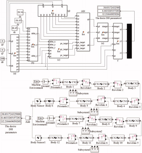
The parameters in and are regarded as the inputs, the corresponding output of the hybrid simulation model are given in . The expected D-H values (Δpx-desired, Δpy-desired, Δpz-desired) of the OD relative to the CD derived by the Simulink toolbox equals the actual D-H values (Δpx-actual, Δpy-actual, Δpz-actual) of motion obtained from Simmechanics toolbox, that proves the correctness of the endoscopic manipulator’s kinematic algorithm.
Table 1. The parameters of the endoscopic manipulator.
Table 2. The position vector of the OD relative to the CD.
Table 3. The desire and actual D-H value of motion from the current window to objective window.
Simulation analysis of the instrument manipulator’s kinematic
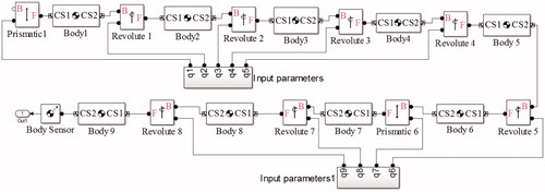
The simulation models are built by virtue of two sub-modules of the Matlab relative to the kinematic algorithm of the instrument manipulator based on the DD depicted in . The detailed description of red rectangle is depicted in . The expected D-H values derived by the Simulink toolbox equals the actual values produced from SimMechanics toolbox, which validates the correction of the instrument manipulator kinematic algorithm with respect to DD.
Figure 4. The hybrid simulation model of the instrument manipulator.
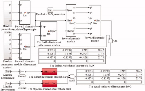
Figure 5. The detailed description of red rectangle shown in Figure 4.
The parameters in are regarded as the inputs, the corresponding output of the hybrid simulation model are given in . The expected D-H values of the surgical instrument relative to the CD derived by the Simulink model equals the actual D-H values of motion calculated from Simmechanics model, that proves the correctness of instrument manipulator kinematic algorithm.
Table 4. The parameters of the surgical instrument manipulator.
Table 5. The required parameters for simulation analysis.
Table 6. The comparison between desired and practical D-value.
Experiment to test the effective of intuitive control algorithm
There are three experiments to test the effective of the intuitive control algorithm: the first experiment is trajectory tracking experiment; the second experiment is intuitive control experiment; last is the gall bladder removal experiments.
Trajectory tracking experiment
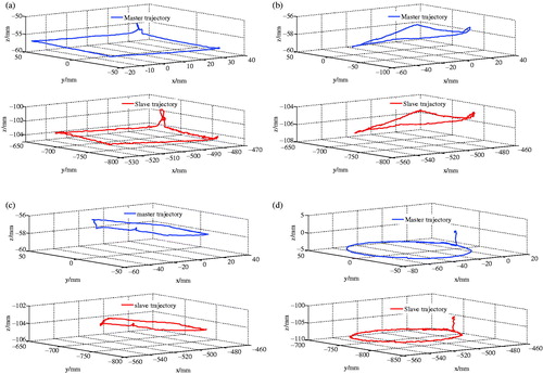
Trajectory tracking experiment is used to test the correction of the forward and inverse kinematics of the endoscopic and instrument manipulators. The master is operated according to the surgeon’s demand, then the surgical instrument or endoscopic manipulators track the motion of the master to achieve the surgical operation. The trajectory tracking is important to accomplish the surgical operation. Four trajectories experiments which are rectangle, triangle, pentagon and circle were finished and the experiment results are shown in . The conclusion that the manipulator can achieve a good track following the motion of master can be drawn in .
Figure 6. Trajectory tracking experiment: (a) Rectangle; (b) Triangle; (c) Pentagon; (d) Circle.
Intuitive control experiment
Intuitive control experiment shown in is applied to validate the kinematic algorithm based on DD. ) are the cumulative position increments (CPI) between the master and the slave in the current vision window following four different trajectories mentioned before. The root mean square error of CPI between the master and slave is shown in . This experiment validates the effectiveness of the intuitive control algorithm. The reason of errors is the hand tremor and machine processing and assembly errors. However, these errors can be compensated by the visual feedback. It can be seen from and that the intuitive control algorithm can achieve excellent performance. The intuitive control algorithm meets the surgical requirement.
Figure 7. Intuitive control experiments: (a) Rectangle; (b) Triangle; (c) Pentagon; (d) Circle.
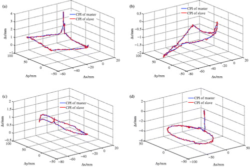
Table 7. The root mean square error of CPI between the master and slave.
Cholecystectomy removal experiment
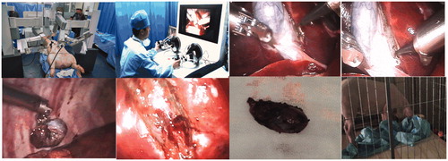
Cholecystectomy removal experiments on pigs were successfully achieved at Harbin Institute of Technology. The whole process is shown in . Three hours after surgery, the pigs wake up and stand up, then pigs start eating, now all pigs were in good health without infection, validating the feasibility of the intuitive control alogrithm. The failure rates of the intuitive control algorithm were zero during all experiments, indicating that the intuitive control algorithm is stable and reliable.
Figure 8. Gall bladder removal experiments.
Conclusion
Forward and inverse kinematics of the MIS robot are achieved based on the screw theory, kinematic algorithm of the MIS robot based on the DD has been set up, then the intuitive control is implemented based on the kinematic algorithm based on the DD. The hybrid simulation experiment based on the MATLAB, test experiments and Cholecystectomy removal experiments validate the effectiveness of forward, inverse kinematics and intuitive control algorithm.
Disclosure statement
The authors report no declarations of interest.
Funding
This study was supported by National High Technology Research and Development Program of China (“863 Program”) (Grant No. SS2012AA041601), National Science Foundation of China (No. 61305139) and Self-Planned Task of State Key Laboratory of Robotics and System (SKLRS201406B).
References
- Sackier JM, Wang Y. Robotically assisted laparoscopic surgery. From concept to development. Surg Endosc 1994;8:63–66.
- Ghodoussi M, Butner SE, Wang Y. Robotic surgery-the transatlantic case. Paper presented at: The International Conference on Robotics and Automation. 2002 May 12–18; Washington, DC.
- Hannaford B, Rosen J, Friedman DW, et al. Raven-II: an open platform for surgical robotics research. IEEE Trans Biomed Eng 2013;60:954–959.
- Lum MJ, Friedman DC, Sankaranarayanan G, et al. The RAVEN: design and validation of a telesurgery system. Int J Robot Res 2009;28:1183–1197.
- Hagn U, Konietschke R, Tobergte A, et al. DLR MiroSurge: a versatile system for research in endoscopic telesurgery. Int J Comput Assist Radiol Surg 2010;5:183–193.
- Bogue R. Robots in healthcare. Ind Robot 2011;38:218–223.
- Berkelman P, Ma JA. A compact modular teleoperated robotic system for laparoscopic surgery. Int J Rob Res 2009;28:1198–1215.
- Speidel S, Delles M, Gutt C, et al. Tracking of instruments in minimally invasive surgery for surgical skill analysis. Paper presented at: International Workspace on Medical Imaging and Virtual Reality. 2006 Aug 17–18; Springer, Berlin-Heidelberg, Germany.
- Weede O, Mönnich H, Müller B, et al. An intelligent and autonomous endoscopic guidance system for minimally invasive surgery. Paper presented at: The International Conference on Robotics and Automation. 2011 May 9–13; IEEE, New York, NY.
- Weede O, Bihlmaier A, Hutzl J, et al. Towards cognitive medical robotics in minimal invasive surgery. Paper presented at: Conference on Advances In Robotics; 2013 July 28–30; ACM, New York, NY.
- Reiley CE, Lin HC, Varadarajan B, et al. Automatic recognition of surgical motions using statistical modeling for capturing variability. Stud Health Technol Inform 2008;132:396–401.
- Wei GQ, Arbter K, Hirzinger G. Real-time visual servoing for laparoscopic surgery. Controlling robot motion with color image segmentation. IEEE Eng Med Biol Mag 1997;16:40–45.
- Staub C, Lenz C, Panin G, Knoll A, et al. Contour-based surgical instrument tracking supported by kinematic prediction. Paper presented at: International Conference on Biomedical Robotics and Biomechatronics. 2010 Sept 26–29; IEEE, New York, NY.
- Tully S, Kantor G, Zenati MA, et al. Shape estimation for image-guided surgery with a highly articulated snake robot. Paper presented at: International Conference on Intelligent Robots and Systems. 2010 Sept 25–30; IEEE, New York, NY.
- Murray RM, Li Z, Sastry SS, et al. A mathematical introduction to robotic manipulation. New York: CRC Press; 1994.