
Abstract
A non-mydriasis optical system for binocular fundus camera has been designed in this paper. It can capture two images of the same fundus retinal region from different angles at the same time, and can be used to achieve three-dimensional reconstruction of fundus. It is composed of imaging system and illumination system. In imaging system, Gullstrand Le Grand eye model is used to simulate normal human eye, and Schematic eye model is used to test the influence of ametropia in human eye on imaging quality. Annular aperture and black dot board are added into illumination system, so that the illumination system can eliminate stray light produced by corneal-reflected light and omentoscopic lens. Simulation results show that MTF of each visual field at the cut-off frequency of 90lp/mm is greater than 0.2, system distortion value is −2.7%, field curvature is less than 0.1 mm, radius of Airy disc is 3.25um. This system has a strong ability of chromatic aberration correction and focusing, and can image clearly for human fundus in which the range of diopters is from −10 D to +6 D(1 D = 1 m−1).
1. Introduction
Capillaries distributed in the retina of human eye are small arteries and veins that only can be observed in human’s body. Systemic diseases such as hypertension, atherosclerosis, stroke, myocardial infarction and cardiovascular disease all exert influence on characteristics of retinal vessel, such as width, tortuous and branching angle [Citation1]. Early pathological evidences of human retinal diseases should be checked, screened and treated as soon as possible, so that irreversible loss of vision can be prevented [Citation2–4]. Fundus camera is a kind of medical device, which is used to capture retinal image, and is also an important tool to exam retina for patients. Therefore, fundus camera plays an extremely important role in clinic.
Since 2 D image generated by fundus camera cannot display the spatial relationship of 3 D fundus elaborately and truly, it brings some inconvenience for doctors’ diagnosis [Citation5]. Three-dimensional reconstruction of fundus images can present true sensorial effect of 2 D image data to doctors to overcome the shortcomings of three-dimensional information loss in imaging. Meanwhile, it will enable doctors to observe size, spatial location and geometry space of fundus nidus more accurately and clearly and reduce negative influences on diagnosis caused by doctors’ subjective judgment and lack of clinical experience. Three-dimensional reconstruction of fundus image can assist doctors to analysis fundus nidus qualitatively and quantitatively, and improve the accuracy of diagnosis and the level of medical diagnosis.
For three-dimensional reconstruction of retina, modern advanced optical coherence tomography (OCT) only provides local tomographic images [Citation6] of retina and its instrument is expensive. The three-dimensional reconstruction algorithm of OCT is complex. On the contrary, three-dimensional reconstruction of human retinal image captured by fundus camera has low cost and is easy to implement. Fundus camera meets the actual needs of the majority of patients. Local three-dimensional reconstruction of glaucomatous optic disk was proposed by Corona et al. [Citation7] and external three-reconstruction of fundus based on actual shape of retina was studied by Ataer-Cansizoglu et al. [Citation8] However, they both achieved three-dimensional reconstruction using multiple images registration and their effects are not ideal. The main reason is that living human’s eye may produce tremors, drifts, micro saccades and other physiological phenomena, which lead to higher order aberration [Citation9]. States and qualities of fundus images may be time-varying, so the effect of registering rectification may be affected. Three-dimensional reconstruction of fundus images with binocular stereo vision has a relatively high accuracy, because the two fundus images are captured at the same time. For three-dimensional reconstruction based on binocular stereo vision, the primary problem is how to obtain two human fundus images at the same time, which should have certain overlapped area and visual angle difference. Nevertheless, current fundus cameras are all monocular systems, which cannot capture two fundus images at the same time.
In this paper, an optical system for binocular fundus camera is designed, which can capture two images of the same fundus retinal region from different angles at the same time. Meanwhile, effective overlap area of the two images is 100% and their visual angle difference is 11°. Since the two fundus images contain more information than a single image, they can reflect the true status of fundus more accurately. Consequently, the system is able to improve the accuracy of disease diagnosis greatly. As the designed system can capture two fundus images, it meets the need of three-dimensional reconstruction of fundus based on binocular stereo vision. Moreover, the imaging system belongs to parallel optical system and the two images captured can be used in three-dimensional reconstruction directly without any corrective preprocessing.
2. Optical system design
2.1. Overall structure
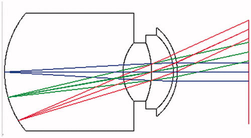
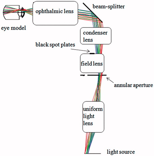
The optical system of binocular fundus camera is consisted of two parts: imaging system and illumination system, as shown in . Imaging system includes ophthalmic lens, common objective lens, reflector group and imaging objective lens. Reflector group and imaging objective lens coordinate with each other to separate the main optical path into left and right parallel sub-optical paths. Beam-splitter is placed behind ophthalmic lens so that it can be joined into illumination system. Illumination system is composed of light source, uniform light lens, field lens, condenser lens, beam-splitter, annular aperture and black spot plates. In order to reflect the effect of optical path imaging truly, this design uses Gullstrand Le Grand eye model, which is closer to real human eye as measured eye. Its structure includes corneal anterior surface, corneal posterior surface, lens anterior surface, lens posterior surface and so on, as showed in . In order to analyze focusing ability of the optical system objectively, this design uses Schematic eye model proposed by R. Navarro [Citation10] to analyze the influence of ametropia in human eye on the imaging quality of the optical system.
Figure 1. Optical system for binocular fundus camera.
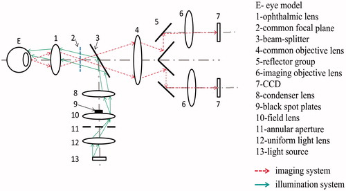
Figure 2. Gullstrand Le Grand eye model.
This system belongs to non-mydriatic fundus camera. For this system, simulation results show that imaging quality is best when the parallax angle between the two fundus images captured is 11°. Overlap area with better image quality than other images is selected for imaging, and the visual angle of overlap area is 30°. In order to reduce cost and complete imaging, 1 inches CCD of 3 million pixels is selected as imaging chip, and its pixel size is 6.25um(H) × 6.25um(V); According to requirements of medical light source, sodium lamp whose wavelength is 589 nm is selected as light source and its spectral range is 560 nm∼610 nm; Magnifying power of the imaging system is 1.07, and the cut-off frequency of object is 96.3pl/mm, that is our system can distinguish the structure unit of 5.2 um. In order to make operation and adjustment more convenient, the size of this optical system is set to be 480 mm × 100 mm ×200 mm.
2.2. Imaging system design principle
Design idea of this optical system for binocular fundus camera is derived from stereomicroscope. Stereomicroscope is a binocular microscope with 3 D sense, and allows eyes to observe subjects from different angles. Stereoscopic vision determines that the stereomicroscope needs two identical optical paths. Finally, two fundamental forms of stereomicroscope are generated, called parallel optical path system and tilted optical system [Citation11], as shown in .
Figure 3. Two forms of stereomicroscope (a) Parallel optical system and (b) Tilted optical system.
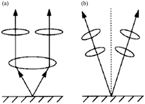
Because the optical axis of tilted optical path system is not perpendicular to the surface of subject, imaging quality of off axis object must be affected and imaging ranges are limited. Instead, the optical axis of parallel optical path system is perpendicular to the surface of subject, and its imaging ranges will be wider. Some devices can be placed in two parallel sub-optical paths behind common objective lens, such as observing device, photographic device and so on. It is beneficial to the diversification of the system function. Furthermore, images formed via parallel optical path are more suitable for three-dimensional reconstruction of tiny subjects. As a result, parallel optical system is more in line with the design’s requirement.
The light reflected from normal human eye is similar to parallel light and doesn’t meet the requirements of imaging light for the stereomicroscope. Therefore, a real image of retina surface is captured behind ophthalmic lens first, and then common objective lens receives the light from this real image. The object focus of common objective lens and the image focal of ophthalmic lens are overlapped at a common focus, that is, the optical interval Δ = 0. This process is similar to the inverse application of the Kepler telescope imaging system which conforms to the principle of optical path reversibility. The reflected light of human eye is divided into two parallel sub-optical paths by reflector group via common objective lens. The two light contain different parallax information. Hence the final two images will also have some parallax.
2.3. Imaging system design
In the imaging system, the optical axis of common objective lens is parallel to the optical axis of two parallel sub-optical paths, in which left and right sides are symmetric to each other. This imaging system is a non-coaxial optical system with complex optical path. To ensure that the two images are clear eventually, our system selects flat field objective lens as common objective lens. According to the requirements of design, a 4-pieces objective lens is selected as initial model of common objective lens, and the objective lens belongs to large field telescope objective lens. The advantage of this objective lens lies in the addition of meniscus lens to the structure, thus objective lens of this structure improves the imaging quality of field edge and ensures clear imaging of two parallel sub-optical paths.
To avoid touching between patient's eyelashes and surface of lens when patients are checked, in general case, the working distance of devices should not be less than 10 mm. Therefore, the working distance of our designed optical system is set to be 12 mm. Ophthalmic lens is nearest to human eye in the imaging system, whose main role is capturing a clear image behind retina. This design uses Erfle eyepiece as initial structure of ophthalmic lens, which has the characteristics of achromatic components, small advanced aberration, and its field angle is broader than other lens.
For the design of imaging objective lens, considering that exposure of human eye must be limited in a safe range, imaging of this imaging system should be carried out in two pieces of CCD at the same time, and each piece of CCD receives less than half of the total light energy. But the brightness of illumination is much weaker than that of monocular fundus camera. The imaging quality must be affected. For this reason, it is necessary to use high-power objective lens, which is also able to image for weak light to overcome this shortcoming. This system selects Petzval objective lens as initial model of imaging objective. Petzval objective lens is a large aperture objective lens, and has a great correction of spherical aberration and coma. Aplanatic lens is added into the structure to further broaden visual field and relative aperture.
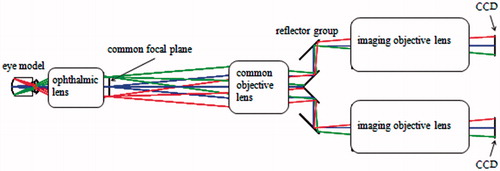
The reflector group is composed of four mirrors. Reflector group and imaging objective lens coordinate with each other to separate the main optical path into left and right parallel sub-optical paths. Imaging objective lens and CCD are located on two parallel sub-optical paths to complete the final imaging task. The reflector in reflector group can also be replaced by a prism. The distance between two parallel sub-optical paths can be adjusted by changing the distance between the mirrors in reflector group. The distance between reflector group and common objective lens has some influences on imaging quality. The diagram of imaging system is shown in .
Figure 4. Diagram of imaging system.
2.4. Illumination system design
The fundus itself is not glowing, and some external light source is needed to illuminate it. Moreover, the reflected light of fundus is received by imaging system [Citation12]. The fundus camera system mostly achieves illumination in coaxial way, in which illumination system and imaging system share the ophthalmic lens through Beam-splitter. This system also ensures uniformity of illumination in this way. The central area of human cornea has a high reflectivity for the light of human eye. If the reflected light enter imaging system, they will exert a serious influence on imaging quality. In order to avoid the influence of corneal reflected light on imaging and ensure the full use of light energy, the system takes the method of irradiating the lighting from corneal edge, namely annular illumination. It is necessary to place an annular aperture in the illumination system to form annular illumination. The light actually enters human eye from outer ring of cornea so as to bypass the central area of cornea. As illumination system and imaging system share ophthalmic lens, the surface of ophthalmic lens will produce a small amount of reflected light into the imaging system to form a ghost image. However, the presence of ghost image will affect imaging quality. The addition of black spot plates in the imaging system is desirable to shield the reflected light which can form ghost image [Citation13].
Optic aperture of human pupil in non-mydriatic state is 3 mm ∼7 mm. External diameter of annular spot formed on the surface of cornea is less than 7 mm and inner diameter is greater than 4 mm. A semi-transparent mirror with an angle of 45° is placed on the back of ophthalmic lens, while condenser lens and field lens are placed below semi-transparent mirror. The position where luminous flux is high and a standard annular illumination spot exists on the surface of the cornea is the best position of the annular aperture. The best position between field lens and uniform light lens is selected by multiple simulation testing. Sodium lamp is placed behind uniform light. Location of the black spot plates is obtained by tracing light reversely, and then they should be placed in front of field lens. The diagram of illumination system is shown in .
Figure 5. Diagram of illumination system.
3. System optimization and result analysis
3.1. System optimization
Optimal design and results analysis of this optical system are achieved with ZEMAX and LightTools. As this system is a complex non-coaxial system, in order to simplify the design of it, piecewise-local optimization is used firstly and then whole optimization is implemented. The design is divided into three parts for local optimization including light separation, bilateral imaging and illumination system.
According to the reversibility theorem of optical path, if the imaging quality of reverse optical path is good, the imaging quality of forward optical path must also desirable. The local optimization of light separation and the illumination system both use the reversibility theorem of optical path. Local optimization of bilateral imaging is finished on the basis of local optimization of light separation. After the local optimization, three parts local optical path are combined to optimize the aberration of the whole imaging system, such as spherical aberration, chromatic aberration, distortion and field curvature. Consequently, the cut-off frequency of MTF curve is improved and good imaging quality can be guaranteed.
3.2. Imaging quality analysis
Because exposure quantity of human eye cannot exceed safe range, in which the total light energy is constant. According to the law of energy conservation, CCD of monocular fundus camera can receive most of light energy with high imaging quality. On the contrary, binocular fundus camera receives light energy with two CCDs at the same time. The light energy received by each CCD is not more than half of the total light energy. Under same conditions, the imaging quality of binocular fundus camera must be lower than that of monocular fundus camera. For binocular fundus camera, if the imaging quality of each piece of CCD reaches imaging standard of monocular fundus camera, it can fully prove that the imaging quality of this binocular fundus camera is very good.
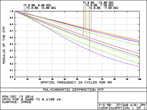
Considering that the two parallel sub-optical paths of binocular fundus camera are symmetric to each other in the structure and their imaging quality is completely consistent, the imaging condition of only one optical path is analyzed. From the MTF curve of imaging system shown in , it can be seen that MFT of each visual field is greater than 0.2 at 90lp/mm. It meets the requirement that CCD resolution is greater than 80lp/mm, transfer function curves of different visual fields are smooth and imaging quality is ideal. The imaging quality is also accord with the imaging standard of monocular fundus camera.
Figure 6. Curves of Modulation Transfer Function (MTF).
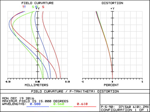
If there is a large field curvature in the imaging system, each point on a large plane object cannot be imaged clearly on the same image plane at the same time. Moreover, the field curvature must be very small because the requirement of CCD is that image planes must be located in the same plane. Field curvature curves are shown in , in which the maximum of field curvature is 0.1 mm and meets the requirement of plane imaging. An intersection point between the main light via the optical system and Gauss image plane is formed. Distortion makes height of the intersection point not equal to ideal height of image, and makes images lose their similarity relative to objects. Although the distortion does not affect definition of image, it makes image distort. Studies have shown that human eye does not feel a significant change when distortion is less than 5%. As the distortion curves shown in , the maximum of distortion value is only −2.7%. So the image has no obvious distortions.
Figure 7. Field curvature and distortion curves.
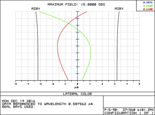
Chromatic aberration curves when pupil diameter is 6 mm is shown in . The values of chromatic aberration in every visual field are all within Airy disc, in which the maximum value is 3.1 um. As the Airy disc radius of imaging system is 3.25um, pixel size of the selected CCD is 6.25um(H) × 6.25um(V) and correction of chromatic aberration meets the requirement. Thus, this system has overcome the influence of the chromatic aberration of human eye itself on imaging quality.
Figure 8. Chromatic aberration curves.
3.3. Diopter analysis
Above design is based on a normal human eye model called Gullstrand Le Grand optical eye model. Nevertheless, different human eyes have different diopters. Typical examples are myopia and hyperopia. In order to capture clear fundus images for the patients with ametropia, imaging system is required to have capability of diopters adjustment. Based on existing adjustment mode of monocular fundus camera and considering that operation must be simple and convenient, our system uses a more common adjustment mode which is moving ‘whole optical system + CCD’. The relative offset of this system is defined as Δn, the relative offset of CCD is defined as Δm.
Modern medicine has confirmed that changes of human eye diopters may cause changes of multiple eyeball parameters besides axial length and lens curvature. In order to simulate the role that changes of human diopters exert on imaging quality of this optics system, Schematic eye model constructed by R.Navarro is employed. When the human eye diopters are changed, anterior lens radius plays a major role and posterior lens radius and aqueous thickness also play some roles. shows the relational expressions of anterior lens radius, posterior lens radius, aqueous thickness, lens refractive index and lens thickness with the change of the human eye diopters given by R. Navarro.
Table 1. Relational expressions of lens parameters with the change of human eye diopters.
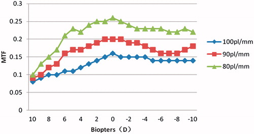
Corresponding values of each lens parameter with different diopters can be calculated using these relational expressions, and values of Δn, Δm and MTF can be obtained by simulating and testing in ZEMAX. It can be seen from the results of simulation and test that with the change of human eye diopters, the change of Δn is not as obvious as Δm and the range of Δn is only within 0.571 mm. This means that clear fundus image can be obtained only by moving CCD when the system is in practical focusing. shows changes of MTF values of the whole visual field at 100lp/mm, 90lp/mm and 80lp/mm with the change of human eye diopters. At 100lp/mm and less than 100 lp/mm, the MTF values are better than those in the figure. Apart from +9 D and +10 D, the values are higher than 0.1. In the range from -10 D to +6 D, the MTF values of the whole visual field at 80lp/mm are above 0.2. These test results show that imaging system can imaging clearly for the refraction from −10 D to +6 D in the human eye, and meets the requirement of design.
Figure 9. MTF curves with different diopters.
3.4. Illumination effect analysis
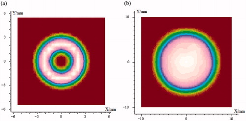
In this paper, LightTools software is used to analyze the lighting effect of the illumination system, and the ray tracing is 1 million. The simulation results are shown in . It can be seen from that the effective lighting radius of annular illumination spot in the pupil ranges from 1.5 mm to 3.5 mm. This is a good way to avoid the region where the corneal center curvature is large, thus avoiding the generation of corneal stray light. shows the Illumination spot at fundus, and the spot uniformly covers the illumination area with diameter of 14 mm, thus this system meets the requirement of design. The illumination system selects a dim light source widely used in medicine, and the wavelength of the dim light ranges from 560 nm to 610 nm. The illumination system can match well with the CCD receiver.
Figure 10. Simulation of illumination uniformity in fundus (a) Illumination annulus at the pupil of the eye and (b) Illumination spot at fundus.
4. Conclusion
To reflect performance of this optical system for binocular fundus camera truly, Gullstrand Le Grand eye model is introduced to simulate the measured normal eye in the imaging system and Schematic eye model is used to test the influence of ametropia on imaging system. Simulation results have shown that in this system, the MTF of each visual field at the cut-off frequency of 90lp/mm is greater than 0.2. The system can imaging clearly in the −10 D to +6 D dioptric range and the whole imaging quality is good. The mirrors utilized in this design are spherical mirrors, which are easy to manufacture. As the optical system can capture two images of the same fundus retinal region from different angles at the same time, it makes three-dimensional reconstruction of the fundus with binocular stereo vision possible. Therefore, this system has the advantage of promoting the development of medical imaging technology and improving the accuracy of medical diagnosis.
Disclosure statement
No potential conflict of interest was reported by the authors.
Additional information
Funding
References
- Ogagarue ER, Lutsey PL, Ronald K, et al. Association of ideal cardiovascular health metrics and retinal microvascular findings: the atherosclerosis risk in communities study. J Am Heart Assoc. 2013;2:430–440.
- Rowe S, MacLean CH, Shekelle PG. Preventing visual loss from chronic eye disease in primary care: scientific review. J Am Med Assoc. 2004;291:1487–1495.
- Wong EY, Keeffe JE, Rait JL, et al. Detection of undiagnosed glaucoma by eye health professionals. Ophthalmology. 2004;111:1508–1514.
- Garg S, Davis RM. Diabetic retinopathy screening update. Clinical Diabet. 2009;27:140–145.
- Chen J, Peng C. Three-dimension reconstruction of ocular fundus image. J Biomed Eng. 2008;25:177–181.
- Cable AE, Potsaid B, Lu CD, et al. Handheld ultrahigh speed swept source optical coherence tomography instrument using a MEMS scanning mirror. Biomed Optics Express. 2013;5:293–311.
- Corona E, Mitra S, Wilson M, et al. Digital stereo image analyzer for generating automated 3D measures of optic disc deformation in glaucoma. IEEE Trans Med Imag. 2002;21:1244–1253.
- Ataer-Cansizoglu E, Taguchi Y, Kalpathy-Cramer J, et al. Analysis of shape assumptions in 3D reconstruction of retina from multiple fundus images. IEEE International Symposium on Biomedical Imaging; 2015 April 16–19; New York, USA.
- Betul S, Barbara L, Xavier L, et al. Adaptive optics with pupil tracking for high resolution retinal imaging. Biomed Opt Express. 2012;3:225–239.
- Navarro R, Santamaría J, Bescós J. Accommodation-dependent model of the human eye with aspherics. J Opt Soc Am A. 1985;2:1273–1281.
- Lu JN, Gao ZL. Design of the new 0.8×∼8× zoom-stereo microscope objective. Optical Instruments. 2011;33:36–42.
- Yang JQ, Cheng DW, Wang QF, et al. Design of a novel wide view-field angle and anti-stray-light fundus camera. Acta Optica Sinica. 2012;32:204–210.
- Li C, Sun Q, Liu Y, et al. Design of uniform illumination system of fundus camera and its stray light shield. Chinese J Optics Appl Optics. 2010;3:363–368.