
Abstract
Purpose: This paper aimed to explore the design and application of a customized navigation board for lumbar disc ablation.
Methods: Eight cases of lumbar disc herniation (diagnosed by spiral computerized tomography, CT) to be treated via intervertebral ablation using a path from the skin to the herniated intervertebral disc were included. The lumbar vertebrae, sacrum, and skin (adhered to a standard base, Figure 1) were reconstructed based on continuous spiral CT slices. The path was designed by the surgeon (Figure 2) to be line between the base and the puncture point, and was guided by the navigation board. The board was prototyped and used in ablation localization as a guide canal. The intra- and post-operative complications were recorded during the operation and 48-hours post operation, respectively.
Results: In all eight cases, target discs were punctured after a duration ranging from 6 to 13 minutes. No complications were observed either during the operation or at 48 hours post-operatively.
Conclusion: This customized navigation board could promote the accuracy and diminish the duration of intervertebral disc ablation. A stereolithography apparatus (SLA) and photosensitive resin could generate a customized reverse guide board with high fidelity for intervertebral disc ablation. Manually performed rigid registration can meet the accuracy requirements. The results presented in the present paper demonstrated that rapid prototyping via an SLA and photosensitive resin could maintain the accuracy and dynamic stability of a customized navigation board for lumbar disc ablation.
Introduction
With the development of three-dimensional (3 D) technology such as Java 3 D, OpenGL (Open Graphics Library), and DirectX, the accuracy of 3 D-modeling software and algorithms has improved to the millimeter or even nanometer scale [Citation1]. Based on the high resolution of lasers and the maturity of digitally-controlled machining tools, the accuracy of rapid prototyping has also been enhanced to the sub-millimeter scale, enabling the use of microstructures such as continuous carbon fibers [Citation2]. Customized assistive medical instruments, such as artificial limbs, pathological models, and operation navigation boards, can be developed and produced with high resolution and rapid prototyping [Citation3]. Minimally-invasive surgical techniques have entered the orthopedic, general surgery, and cosmetic surgery fields, among others [Citation4]. Lumbar intervertebral disc protrusion is a common disease of the spinal column. While conservative therapy is used in mild cases, ablation has a better therapeutic outcome in severe cases, and has been commonly performed in recent years [Citation5–7]. Traditional intervertebral endoscopy must be performed under continuous X-ray guidance, which could result in the doctor and patient receiving excessive exposure to radiation. Conversely, in patients, with a high body mass index (BMI) (>25), the path of the needle can potentially change during puncture, causing serious bleeding, nerve root injury, or even operation failure [Citation8]. The focus of this paper was to identify a rapid and stable method for puncture at the intervertebral disc space using a path designed in a virtual environment. It has been more than 30 years since the development of rapid prototyping or 3 D-printing. The principle of this technology is to manufacture objects layer by layer, and after each layer has been automatically designed in the X-Y (horizontal) plane, the layers are accumulated on the Z (vertical) axis to construct an entire model. The keys elements of rapid prototyping are the correct materials and the accuracy of the equipment. As a common rapid prototyping technology, the resolution of SLA is 0.01 mm on the X-Y plane and 0.1 mm on the Z axis [Citation9]. The percutaneous endoscope has been used for ablation of intervertebral disc protrusions in recent years [Citation10], however, complications such as bleeding and neuralgia have high intra-and-post operative incidence rates due to repeated punctures [Citation8]. The need to repeat a puncture in order to adjust its direction increases the exposure of both the doctor and the patient to radiation. Compared with the traditional puncture process, puncture via a customized or individual navigation board could be safer, and the duration of the operation could be notably diminished. This paper focuses on puncture with the assistance of a customized puncture navigation board manufactured via rapid prototyping.
Methods
Design
Steps 1-5 focus on the process of designing a reverse board based on spiral computerized tomography (CT, Siemens AVATO spiral 64 slice CT, Siemens corp.) images in the form of digital imaging and communications in medicine (DICOM) data
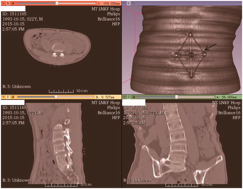
Step 1. The BMI of the eight patients with lumbar disc herniation ranged from 17 to 35. The patients were examined by CT (5 mm original and 0.625 mm digitally resized) along with the base of the navigation board (rapidly prototyped as a standard apparatus by ZhouKe Medical Instruments Technology Co., Ltd.). It is a regular examination for patients before operation with 5 mm CT scan considering lower radiation dose. However, 1 mm CT scan is also common in the hospitals. “Ripple” artefact derives from scanning would be eliminated with linear simulation as demonstrated in Step 5. The navigation board base was 107.8 millimeters long and 77.6 millimeters wide. The scanning range was from the 1st lumbar vertebrae to the sacrum (). The base was attached to the patient via five electrode patches, with the base being subsequently removed while the patches remained on the skin.
Figure 1. Spiral CT examination with the navigation board base, as indicated by an arrow.
Step 2. The DICOM data were imported into 3 D Slicer (version 4.4). The lumbar vertebrae, pelvis, base, and skin were automatically segmented based on gray values and then reconstructed. The models were subsequently exported as STL (stereo lithography) files.
Step 3. After the STL models were imported into Geomagic Studio 16 (Geomagic Corp. USA), the surgeon designed the puncture path as a needle line from the skin to the corresponding intervertebral space where the protrusion was located. Subsequently, the needle, spinal column and base were exported as one STL model, as shown in .
Figure 2. Rigid registration between the reconstructed (rough) and virtual standard (smooth) models showing the puncture path (long cylinder). (a) Registration; (b) Puncture path.
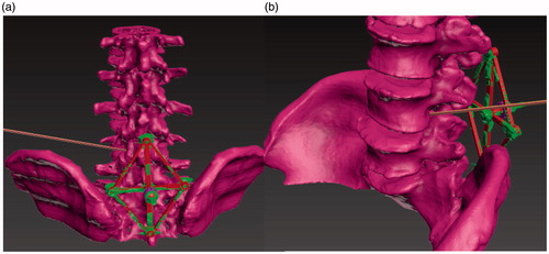
Step 4. These whole models were imported into 3Ds Max (Version 2014, Autodesk Corp. USA), with the standard base model also being displayed (, green). Subsequently, rigid registration between the virtual standard base (, red) and the reconstructed base was executed manually, and the root part of the reverse board was attached to the virtual base ().
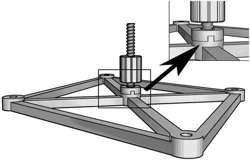
Figure 3. The reverse board root (arrow) and base. The toothed protuberance is used to avoid transformation and rotation between the base and the root.
Step 5. The reverse board was designed according to the skin surface, with smooth lines being used to eliminate the “ripple” on the skin. The width of the board was 17 mm, and the thickness was 2.5 mm (the dynamical mechanical properties of the structure were tested by ANSYS, Inc.). The reverse board model was imported into ANSYS as a .sat file, remeshed with an average mesh of 1 mm 2, given a pressure at polyethylene at pork to simulate the process of puncture.
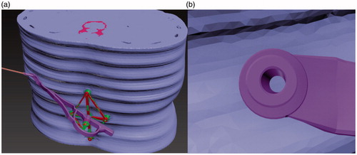
The needle cannel was combined with the puncture path, and the diameter of the cannel was 3.3 millimeters, as shown in . The reverse board was then exported as stl files for rapid prototyping.
Figure 4. Designation of the reverse board (blue) and the needle path. (a) Design of the reverse board. (b) The needle cannel.
Application
Steps 6-8 focus on the clinical application of the reverse board
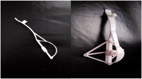
Step 6. The reverse board and nut were manufactured via STL (supported by Jiangsu ZK Medical Instruments Co., Ltd), and the reverse board and standard base were assembled using the nut ().
Figure 5. The reverse board and the whole instrument. (a) The reverse board. (b) The whole instrument, which consists of three parts.
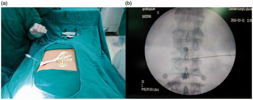
Step 7. Clinical tests were executed in eight patients with intervertebral disc protrusion. The diameter of the puncture needle was 3 mm, while the diameter of the cannel was 3.3 mm. The base was fixed in the same position as it was during CT examination via the electrode patches. The registration was then completed between the pre-operative and puncture processes, as shown in . The puncture was subsequently executed under X-ray guidance to test the accuracy of the instruments ().
Figure 6. Clinical check under X-ray guidance. (a) Attachment of the board. (b) The five electrode patches (concentric circles) and the puncture results.
Step 8. The time spent operating and any complications during and 48 h after operation were recorded ().
Table 1. Operative duration and intra- and post-operative complications with the use of a customized reverse board.
Results
Clinical check (), the base and reverse board were removed after puncture.
shows that the needle entered the intervertebral space corresponding to the herniated disc. The virtual and clinical images in are different, since data from eight patients were used in the present paper.
shows the operative time and intra- and post-operative (48 h post-operation) complications (bleeding, edema, and neuralgia).
Discussion
The reverse board was manufactured via SLA technology, and the accuracy was reliably maintained. This section identifies three important factors of the navigation board design, as follows:
Registration
The key step for accuracy is to register the intra-operative physical position with the pre-operative position. Many rigid registration methods such as frames, and iterative closest points (ICP) are used for neurosurgical navigation during operation, and these registration methods are based on the identification of a rigid transformation matrix, including a translation (T) and a rotation (R) matrix, between a pre-operative image and the intra-operative physical space [Citation11]. Considering soft tissues (fat or muscle) in the abdomen, and the rotation of lumbar vertebra (flection and extension), the intervertebral gaps would be different in the intra-operative physical space compared with the pre-operative location. Thus, considering the movement of the spinal column, surface ‘markers’ are not suitable for localizing a damaged or herniated disc. As such, we designed a rhombus-shaped base that can be attached to the skin on a patient’s abdomen via electrode patches, as shown in . The patches serve as surface ‘markers’, while the distances between the patches reflect the angles of the intervertebral joints. When we reattached the base to the patches, the angles of the intervertebral joints were almost identical to the pre-operative angles. The lateral points of the base maintained the angle in line with the long axis of the spinal column and the rotational angle in the horizontal plane. The initial CT examination should be performed with patients using an arc bracket in the prone position. Manual registration was executed in 3Ds Max2014 (Autodesk Corp.), as shown in , and can be considered a rigid registration.
There are many automatic registration methods for the two virtual models from different coordinate systems [Citation12–14]. For instance, Geomagic can register two virtual models with a global or local method, the former being based on the similarity of the two models while the latter is based on the corresponding fiducials (markers) which should be selected manually in both models in the same order. In the present paper, the base model partly matched the reconstructed model similar to the local registration in Geomagic. Furthermore, the reverse board would be designed after registration, thus, the mesh of the model should be maintained. 3ds Max could support this by setting the geometric center for one marker and attaching others to it, keeping the geometric distance during translation and rotation for registration. The time consumed for registration is approximately five minutes in each case.
Dynamic mechanical structure
Every lumbar vertebra and intervertebral disc is approximately 2.5 cm and 1 cm high. The base should cover at least three vertebrae and two intervertebral discs in order to maintain the intra-operative articular angles of the lumbar vertebrae equal to the pre-operative angles, thus, the length was approximately 2.5 × 3 + 1 × 2 = 9.5 cm. The posterior distance between the two iliac bones is at least 7 cm (at the 4th lumbar level), and the base should be fixed such that the relative spin of the spinal column and iliac bones does not affect its stability. Considering these anatomical data, the base was designed to be 10 cm long and 7 cm wide.
Puncturing the abdomen is a deformable process, and the resistance derived from the muscle and deep fascia could alter the puncture direction. If the angle in the skin changes by one degree, with a radius (distance from the skin to the damaged area) of approximately 150 mm, the target position could deviate by 2 × (150 × sin(0.5)) = 1.31 mm. Clinically, the direction would change randomly without the use of any assistant cannel. Such a cannel must be dynamically stable. In addition, the reverse board must be hard enough to withdraw the pressure from the puncture process, and the handle (the semicircle part of the base) must be dynamically correct. Thus, we reinforced the reverse board with a beam connecting the handle to the middle part of the reverse board (). The reverse board was dynamically stable during the puncture process (). The width and thickness of the reverse board were 17 mm and 2.5 mm, respectively, and photosensitive resin is stable in this size range.
Figure 7. Dynamic structure design of the reverse board. P1 is the pressure from the puncture; P2 is the stress induced by P1; and F1 is the tension stress of the beam reinforcement.
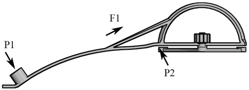
The width of the board is 17 mm, and the thickness is 2.5 mm. 17 mm of the width is compatible for the needle canal: the inner diameter is 3.3 mm and the wall is 5 mm, the sum of the diameter of the canal is 13.3 mm. Furthermore, the width of 17 mm is stable and compatible for the surface of operating skin. 2.5 mm of the thickness is the result of several test for the dynamic property. As shows, the pressure derives from the operator is mainly lied in the canal during the process of puncture, the board could resist the pressure and keep its shape in the range of length 80–160 mm (the distance from the center to the puncture point).
Prototyping materials and design error regulation
Various types of materials are used for SLA. For clinical usage, the material should be tough and non-toxic. The base and reverse board used in this study only contact the skin. The photosensitive resin (supported by Zhongrui Tech. Corp.) is a commonly-used SLA material and meets the requirements for clinical use, as we have previously demonstrated in animals studies.
Upon solidification of the instrument, the model size changes slightly compared with that of the virtual model. As such, it is necessary to maintain a gap between the nut and whorl. Gap requirements vary according to the different materials used. For photosensitive resin, five gap ratios (1%, 2%, 3%, 4%, and 5%) have been tested at a normal temperature. With a total error of approximately 3%, the nut could fit accurately with the whorl, as shown in . We resized the nut to be 3% larger than the whorl on the X-Y plane, with 0% change in the Z axis (see ). The nut and whorl fit accurately (see ).
Figure 8. The nut was 3% larger than the whorl on the X-Y (horizontal) plane.
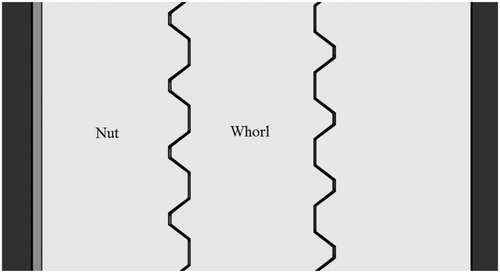
Table 2. The X-Y size ratio and match status between the nut and whorl.
Conclusion
In the present paper, a customized navigation board promoted the accuracy and reduced the operation duration of intervertebral disc ablation. The use of an SLA and photosensitive resin maintained the accuracy. Manually-performed rigid registration met the accuracy requirements; however, while the reliability was good, the efficiency was very low, with the registration time being approximately 10 minutes. Future work should focus on an automatic registration process and corresponding design.
Acknowledgement
The clinical check is supported by Gerontal Rehabilitation Hospital of Nantong.
Disclosure statement
The research was approved by the Nantong Medical Ethics Committee and the consent of the patients.
References
- Simon H, Julian F, Daniel W, et al. Stochastic microstructure modeling and electronchemical simulation of lithium-ion cell anodes in 3D. J Power Sources 2016;336:161–171.
- Nanya L, Yingguang L, Shuting L. Rapid prototyping of continuous carbon fiber reinforced polylactic acid composites by 3D printing. J Mater Process Tech. 2016;238:218–225.
- Xiaojun C, Lu X, Yiping W, et al. Image-guided installation of 3D-printed patient-specific implant and its application in pelvic tumor resection and reconstruction surgery. Comput Methods Programs Biomed. 2016;125:66–78.
- Silvio G, Nicola B, Andrea S, et al. Minimally invasive fixation in tibia plateau fracture using an per-operative and intra-operative real size 3D printing. Injury. 2017;48:784-785
- Zhenhua Z, Min Y, Yi D, et al. Percutaneous bipolar radiofrequency thermocoagualtion for the treatment of lumbar dics hernation. J Clin Neurosci. 2016;30:39–43.
- Chunbo L, Jianfeng P, Yutong G, et al. Minimally invasive pedicle screw fixation combined with percutaneous vertebroplasty for the treatment of thoracolumbar burst fracture. Int J Surg. 2016;36:255–260.
- Guoxin F, Hailong Z, Xiaofei G, et al. Patient-reported and radiographic outcomes of minimally invasive transforaminal lumbar interbody fusion for degenerative spondylolisthesis with or without reduction: a comparative study. J Clin Neurosci. 2016;33:111–118.
- Huadong Y, Kedong H, Lin Z, et al. Minimally invasive surgery through the interlaminar approach in the treatment of spinal tuberculosis: a retrospective study of 31 patients. J Clin Neurosci. 2016;32:9–13.
- Dafeng J, Peng W, Xinhua Z, et al. Feasibility study on accurate rapid prototyping for human hand bones and affiliated artery. Rapid Prototyping J. 2017;23:96–100.
- John E, Kurt ME, Richard GF. Minimally invasive far lateral microendoscopic discectomy for extraforaminal disc herniation at the lumbosacral junction: cadaveric dissection and technical case report. Spine J. 2007;7:414–421.
- Ki-Hoon K, Seung-Hyun L, Min Yong K. A three-dimensional surface registration method using a spherical unwrapping method and HK curvature descriptors for patient-to-CT registration of image guided surgery. 2016 16th International Conference on Control, Automation and Systems (ICCAS): 89–92.
- Yubin L, Qingming Z, Erzhou C, et al. Automatic registration of Terrestrial laser scanning data using precisely located artificial planar targets. IEEE Geosci Remote Sens Lett. 2014;11:69–73.
- Min L, Jian Z, Yulan G, et al. Accelerated coherent point drift for automatic three-dimensional point cloud registration. IEEE Geosci Remote Sens Lett. 2016;13:162–166.
- Nicolas M, Matteo D, Roberto S. Relative scale estimation and 3D registration of multimodal geometry using growing least squares. IEEE Trans Visulization Comp Graphics. 2016;22:2160–2173.