
Abstract
Objective: This paper proposes the development of a novel electromagnetic tracking system for navigation surgery. Main objective is to provide a system able to operate in a wide tracking volume to make easier and efficient the surgical procedures by assuring high measurement accuracy.
Methods: A new field generator consisting in five transmitting coils excited with Frequency Division Multiplexing technique has been developed. Attention is devoted to designing and arrangement of the coils to assure high sensitivity, system scalability and a homogeneous magnetic field inside working volume. A suitable technique based on Look-Up-Table is applied for sensor position calculation and an anthropomorphic robot is used for table calibration.
Results: Experimental tests highlight a good repeatability of the measurement data and a negligible noise influence for the proposed system. The obtained tracking volume is wider with respect to the commercial tracking device used in surgical applications and seem promising.
Conclusion: The main characteristic of the developed system consists of: scalable and modular configuration of Field Generator, high measured sensitivity due to the increased number of transmitting coils with respect to the classical configuration and large tracking volume.
The development of the proposed magnetic tracking systems with high accuracy and wide working volume allows to promote broader utilization of advantaged techniques in surgery procedures for both improving the effectiveness and decreasing the invasiveness of medical interventions.
Introduction
Computed-assisted medical interventions are being very important in modern surgery because they offer many benefits compared to conventional approaches, including increased accuracy, reduction of postoperative pain, reduction of complications and risks for the patient, decreased hospitality time. They are especially used in surgery navigation to provide freehand navigation or guidance for real time precise localization of specific anatomical structures within the human body [Citation1–5] and in neurosurgical and orthopedic applications to monitor motor disorders [Citation6–11].
Surgery navigation system are based on the joint use of tacking system to provide the sensor localization and with respect to the patient and diagnostic imaging techniques (such as Magnetic Resonance Imaging, Computed Tomography, ultrasound imaging) to obtain a real-time imaging of the region of patient body that must be operated. Moreover, imaging techniques often require suitable procedure to improve quality images without increase the radiation dose or the acquisition time [Citation12–16].
The quality and the performance of surgery navigation systems are strongly dependent on accuracy of the used tracking systems. Tracking devices currently used in surgery navigation are mainly based on two different technologies: optical and electromagnetic [Citation5].
Optical tracking systems (OTS) include one or more cameras and a set of dedicated markers to track the object. The high accuracy of optical-sensing systems is essential for tools used in surgical procedures [Citation17, Citation18]. The main limit of this system is that it requires a clear line-of-sight between the patient and instrument trackers and the optical cameras; indeed, any obstacle between sensor and source seriously degrades the tracker's performance. Moreover, OTS are not able to track flexible tools such as needles, endoscopes and catheters. For this reason, optical tracking technique is particularly suitable for radiation treatment, but it is inadequate for intracorporal surgical operations.
Electromagnetic tracking systems (EMTS) localize small electromagnetic sensors in an electromagnetic field of known geometry. These systems suffer from the influence of EM interferences due to the presence of medical diagnostic devices or ferromagnetic objects nearby the field generator, which distort the transmitting signal, and the resulting measurements are affected by both static and dynamic error, [Citation19,Citation20]. summarizes main characteristics and limits for both OTS and EMTS technologies.
Table 1. Comparison between EMTS and OTS.
EMTS are the main systems used in image-guided surgery. The signal of electromagnetic sensor used for volume tracking is inversely proportional to fourth power of the distance of the sensor from the Field Generator (FG) [Citation21] and this degrades the accuracy for high distance (a typically operanting distance is ). Then, these systems can operate in a limited tracking volume and their accuracy decreases as the distance between the transmitter and the receiver increases. Nowadays it is difficult to have systems able to track small sensors within a volume larger than
.
Main commercial available EMTS used for clinical applications are: NDI Aurora (NDI Medical, Canada), Polhemus Fastrack (Polhemus, Canada) and Ascension MiniBIRD (Ascension Technology, USA).
The aim of this work is the realization of an EMTS with high resolution ( for position and
for orientation) in a volume of
, high reliability and high measurement sensitivity. These characteristics have been obtained by means of both the increased number of transmitting coils and their suitable arrangement, without suffering of distortion due to EM interferences and limits for luminosity and line-of-sight of tracking volume. In this way, it is possible realize a suitable EMTS for surgery with good trade-off between actual OTS and EMTS.
Materials and methods
Design of field generator
The reference magnetic field for EMTS can be provided either with the use permanent magnets [Citation22] or with an electrical circuit in which are present some solenoids. In the latter case, the arrangement of the coils and the type of current passing through them determine the profile and the geometric properties of the magnetic field. Normally, Field Generator consists of at least three coils arranged along Cartesian axes. However, in many cases, EMTS manufacturers customize the field generator to give some benefits such as better placement, greater tracking range and low distortions.
In a previous study [Citation23] the analysis of different transmission methods used EMTS has been carried out by comparing the different performance in terms of reduction in time measurements, interference and circuital complexity.
In this work the realization of a 5 channels EMTS -FDM transmitter (with nominal frequencies ,
,
,
,
is proposed. Primary elements which have to be designed in EMTS are coils for both the field generator and the sensor.
For FG designing, attention is devoted to the single coil geometry and to the arrangement of FG coils to have system scalability and uniform distribution of the magnetic field inside the tracking volume.
The analytical expression of axial magnetic fieldof a single coil can be obtained by means of Biot-Savart law [Citation1]:
(1)
where is the magnetic permeability in vacuum,
and
are the internal and external radius of the coil respectively,
in the coil length,
is the number coil turns along
, and
is crossing current.
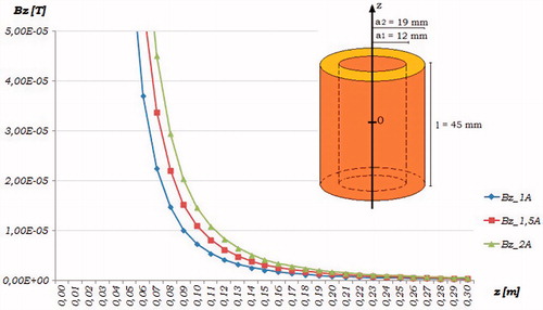
In order to meet the IEEE rules on magnetic field values within tracking volume [Citation24,Citation25], the following physical parameters for each coil have been used: ,
,
, and then a thickness coil d =
, as shown in .
Figure 1. Behaviour of magnetic field for different current values and for wire diameter of
Taking into account that magnetic field value increases when and
increase, while it decreases with the increasing of
, a parametric simulation has been carried out to optimize the system performance. Then, different simulation tests have been performed by varying the crossing current values (
,
,
) and the diameter of the cross-section wire (
,
,
) for a variable number of layers
from
to
, along thickness
.
shows an example of simulation of magnetic field behaviour as function of distance from coil center, for different current values and for a wire diameter of 1 mm. The simulation results show that for the magnetic field value obtained in a distance of
exceeds the threshold level in the above mentioned IEEE rules.
By analysing the test results, it is possible to define the best configuration for each coil consisting in a crossing current of , a cross-section of
,
and
. This configuration makes a rough estimate of total wire length
, and a wire resistance
.
To obtain the maximum gain for the device’s frequency response, it is desirable to work in resonance condition. Then, suitable capacitors have to be connected to each transmitting coil. Due to the limited commercial availability of capacitor values, the resonance condition has been obtained by using the effective values listed in .
Table 2. Parameters for resonance condition.
Once defined the characteristic parameters for a single coil, the arrangement of the transmitting coils must be chosen. The simpler configuration of FG to minimize mutual EM interference and assure the best uniformity of magnetic field inside the tracking volume includes
orthogonal coils along
,
and
axis. To analyse the behaviour of magnetic flux and to verify the values of magnetic field calculated design phase SW Comsol – Multiphysics [Citation26], was used. . shows the simulating results obtained with three transmitting coils excited by AC signal with physical parameters previously defined and nominal frequencies
,
and
displaced along the axis
,
and
respectively. The results highlight a good uniformity of magnetic field for a fixed distance from the centre of coils configuration.
Figure 2. Comsol simulation of magnetic flux for coils EMTS.

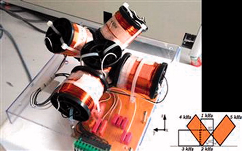
To define the position of the other two coils, it is necessary to minimize the changing in the resonance condition of each coil due to mutual coils interference. In the optimal case both and
coils are placed at
degrees with respect to the horizontal plane and are orthogonal each other as shown in . Then, this arrangement minimizes the eddy current and respects at the same time the IEEE normative about the Human Exposure to Radio frequency. It provides a transmitting system with a total size of
and a weight of about
.
Figure 3. Arrangement of Transmitting coils EMTS.
Experimental set-up of EMTS
To implement the experimental set-up of the proposed EMTS, a DAQ-National Instruments device is used both to generate the sinusoidal waveforms for transmitting devices and to acquire signal by the sensor. The experimental set-up shown in includes:
Figure 4. Experimental set-up for the proposed system.
DAQ device NI cDAQ7192 including NI 9263 Analog Output module [Citation27] to generate
sinusoidal signals for tramsmitting colis, NI 9215 Analog Input module [Citation28] to acquire signal of the receiving coil sensor and a
Field generator previously described;
Coil sensor by NDI [Citation29]. The sensor inserted into the tracking volume provides a induced voltage that is proportional to the excitation magnetic field at the sensor localization [Citation29]. It is shielded from electromagnetic interferences in order to measure the local value of magnetic flux density within
Voltage signal induced in the sensor coil is sum of waveforms, then, a filtering process is necessary for components extracting. For this, a filter bank consisting in
digital band pass IIR – Butterworth filters with high selectivity, narrow band
and center frequencies equal to the resonance frequencies of transmitting coils are used.
A suitable and dedicate software for signal acquisition and elaboration is developed in LabVIEW® environment using built-in and custom-built blocks. It represents a helpful tool to acquire and manage several data an than it widely used in different application fields ranging from image-based navigation, remote sensing, energy monitoring or devices test and characterization [Citation30–33]
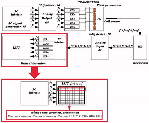
shows the complete block diagram for experimental set-up of EMTS.
Figure 5. Block diagram of experimental set-up for EMTS with Look-Up-Table.
Sensor position calculation
Different calibrating techniques have been developed for position tracking system evaluating [Citation29].
In the proposed study, a voltage/position conversion method based on writing and reading a Look-Up-Table (LUT) is used to evaluate the sensor position of starting from the acquired sensor voltage.
This table provides a univocal association between five components of sensor voltage values measured into tracking volume and sensor position (coordinates ,
and
of the sensor). The main advantage of this method with respect to common run-time calculation mainly based on magnetic dipole mathematical model [Citation34], is the speed in recovering stored data.
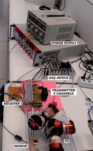
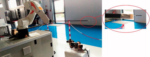
For Table calibrating phase the anthropomorphic robot Kuka [Citation35] is used. Kuka is a DoF robotic arm used to execute measurements for the calibration of the proposed EMTS. It includes mechanical and motion control parts to scan a designed shape trajectory within a volume of
with a resolution step of
. The electromagnetic sensor is placed at the end of a carbon pole mounted on Kuka’s arm, the FG is placed at the foot of robot (as shown in ); the TX/RX electronic part, the DAQ system and the current supply are placed far from the field source to avoid EM interferences.
Figure 6. Kuka robot with sensor and FG.
During the calibration phase of system, each cell value of the matrix is calculated and stored in a txt file. Each row consists in height values: five voltage components and three Cartesian coordinates.
For managing of remote control and the writing of the LUT of EMTS, a Client/Server system based on communication protocol TCP/IP and two different graphical interfaces are used. Robot and PC are connected through Ethernet communication. The Server coordinates robot activities and manages the resource sharing among one or more Clients. Client interface, developed in C++ language, allows the setting of speed movement, initial coordinates and starting coordinates for scanning, dimensions of mapping volume, the incremental step ,
,
along
directions and the shape of trajectory.
Results
Several experimental tests are carried out or both calibrating phase and evaluating the performance of the proposed system in terms of noise and repeatability. For testing, suitable trajectories obtained by setting point-to-point (PTP) are used. Low velocity scan is set to avoid rough accelerations.
Noise evaluation
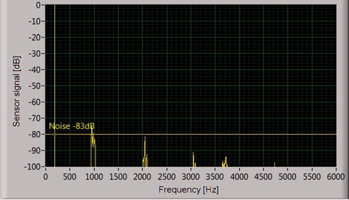
Firstly, the system has been characterised in terms of noise evaluation in static condition. For this, the sensor is placed in a fixed position to from FG. The measurement of the sensor signal has been carried out with the five transmitting coils turned off. The experimental results highlight that all spectral components of sensor voltage are lower than
, as shown in .
Figure 7. Spectral components of sensor signal with transmitting coils turned off and sensor palced at 60 cm from FG.
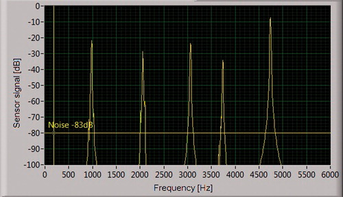
Successively, same measurement has been performed with transmitting coils turned on by obtaining spectral components of sensor signal significantly higher than as shown in .
Figure 8. Spectral components of sensor signal with transmitting coils turned on and sensor placed at 60 cm from FG.
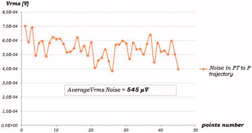
Moreover, the sensor is moved in a fixed trajectory to evaluate the noise influence in dynamic conditions. With transmitting coils turned off, the sensor tracks a trajectory in plane at a distance of 100 cm from FG. The dimension of scanned
plane is
with the following steps:
,
,
. Then, the performed trajectory consists in
points.
The acquired noise signal, shown in , provides an average value inside the plane of
, while it decreases about one order of magnitude outside the tracking volume.
Figure 9. Voltage sensor signal plane scans with a sensor distance from FG of
and transmitting coils turned off.
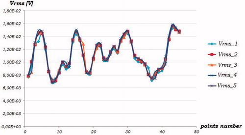
Repeatability
In a second test, five successive scans of the same trajectory in the plane previously described have been performed to evaluate the repeatability of the acquired signal sensor. The experimental results (shown in ) highlight a good repeatability of the measurement data by obtaining a mean error of
. Moreover, the amplitude of sensor signal is two orders of magnitude higher than the data obtained in the noise evaluation and this conforms the negligibility of the noise.
Figure 10. Voltage sensor signal for the 5 consecutive scans of xy plane with sensor distance from FG of 1 m.
Discussion
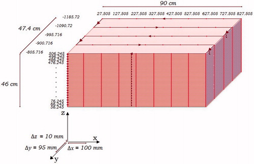
To perform LUT calibration it is necessary move the sensor coil, manually or fixed at the end of a mechanical arm, so that it can be map a fixed tracking volume with constant step, along and around the spatial coordinates 3D.
For this aim, a wide working volume with size of has been used. The tracking trajectory (shown in ) is set in modality PTP, with the following steps:
. Then, the total acquisition number is
. The total time for scanning phase is
.
Figure 11. Tracked volume for calibration test.
Measurement voltage components of sensor signal () and position coordinates (
,
,
) provided by KuKa are stored, during volumetric scan, in a Look-Up-Table.
The developed software interface allows to real time monitor each voltage component in frequency domain and the behaviour of total sensor voltage in the time domain.
To verify the repeatability of measurements in different working conditions, some experimental tests have been carried out by varying the region of volumetric scan and the incremental step performed by Kuka robot.
Particularly, four linear trajectories used in the tests have been obtained by fixing both y and z coordinates and by varying x coordinates and incremental steps as detailed below.
shows the behaviour of the voltage sensor for the four analyzed test cases and it highlights a good measurement repeatability of the proposed system. lists the both average and maximum sensor voltage deviation corresponding to same Cartesian coordinates and it highlights that the maximum voltage error is lower than voltage noise evaluated in the previous sub Section.
Figure 12. Behaviour sensor signal for different test cases.
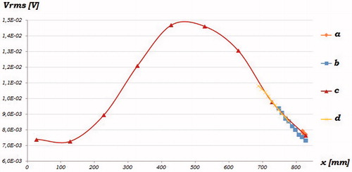
Table 3. Repeatability error.
Moreover, to verify the accuracy of voltage/position conversion based on interpolation data of LUT, a tracking volume consisting in a cube of 1331 points (11 per side) with spatial resolution of 5 mm was used. Two consecutive scans of the cited cube whose centre is 60 cm from FG were performed. After first scan LUT was filled with 1331 datasets each consisting in height values: five voltage components and three Cartesian coordinates. Once the table was filled and then the calibrating LUT was created, a second acquisition of the same tracking volume was carried out. New Cartesian Coordinates were obtained by means of interpolation technique based on the calibrating dataset. The position mean error was evaluated by means of the following expression and it is less than 0.5 mm
where N is the number points of the cube (1331), are the calibration Cartesian coordinates of i-th point and
are the Cartesian coordinates of i-th point obtained by means interpolation of data of the second scan with calibrating values.
To evaluate the effect of increasing in distance from field generator, two additional consecutive scans of the same cube with centre at 100 cm from FG were carried out by obtaining a position mean error of about 2 mm.
Basing on the results obtained in the experimental tests it is possible to develop suitable interpolation algorithms, so that also a volumetric scanning realized with a rougher position step value can be used for calibration of LUT, allowing the reduction of time acquisition for storage voltage values in the LUT.
Conclusions
In the proposed work, basic tracking systems used in guided surgery applications have been analyzed by highlighting limits and advantages.
The development of a novel EMTS is proposed to overcome the limits of the commercial tracking devices used in medical applications principally due to a low accuracy in a large volume to scan. More attention was paid to the design of Field Generator by defining the best suited transmission technique based on FDM, the main parameters of the transmitting coils and their arrangement to minimize the mutual EM interference. The developed experimental set-up is based on Labview and DAQ elements to process data. A Look-Up-Table (LUT) is written to store data acquisition of sensor voltage and the coordinates of sensor position. Experimental tests highlight good performance of the proposed system in terms of both measurement repeatability and low acquired noise signal also by changing the step of scanning, and the capability to appreciate voltage values also at of distance from FG.
The next step for EMTS is the implementation of a method to store also the orientation value (roll, pitch e yaw) around axis
,
and
, in the same LUT.
Further validation tests are currently being in Masmec Biomed company.
Disclosure statement
No potential conflict of interest was reported by the authors.
References
- Soper, TD, Haynor DR, Glenny RW, et al. In vivo validation of a hybrid tracking system for navigation of an ultrathin bronchoscope within peripheral airways. IEEE Trans Biomed Eng. 2010;57(3):736–745.
- Franz AM, Haidegger T, Birkfellner W, et al. Electromagnetic tracking in medicine—a review of technology, validation, and applications. IEEE Trans Med Imaging. 2014;33(8):1702–1725.
- Russo S, Dario P, Menciassi A. A novel robotic platform for laser-assisted transurethral surgery of the prostate. IEEE Trans Biomed Eng. 2015;62(2):489–500.
- Li M, Bien T, Rose G. FPGA based electromagnetic tracking system for fast catheter navigation. Int J Sci Eng Res. 2013;4(9):2566–2570.
- Peters T, Cleary K. Image-guided interventions: technology and application. Springer; 2008.
- Roy SH, Cole T, Don Gilmore L, et al. High-resolution tracking of motor disorders in Parkinson’s disease during unconstrained activity. Movement Disord. 2013:1–8.
- Badesa FJ, Morales R, Garcia-Aracil NM, et al. Dynamic adaptive system for robot-assisted motion rehabilitation. IEEE Sys J. 2016;10(3):984–991.
- Cattin E, Roccella S, Vitiello N, et al. Design and development of a novel robotic platform for neuro-robotics applications: the NEURobotics ARM (NEURARM). Adv Robotics. 2018;22(1):3–37
- Andria G, Attivissmo F, Giaquinto N, et al. Functional evaluation of handgrip signals for Parkinsonian patients. IEEE Trans Instrumentation Meas. 2006;55(5):1467–1472.
- Merlo A, Farina D, Merletti R. A fast and reliable technique for muscle activity detection from surface EMG signals. IEEE Trans Biomed Eng. 2003;50(3):316–323
- Zhoua H, Hu H. Human motion tracking for rehabilitation—a survey. Biomed Signal Process Control. 2008;3(1):1–18.
- Adamo F, Andria G, Attivissimo F, et al. A comparative study on mother wavelet selection in ultrasound image denoising. Measurement. 2013;46(8):2447–2456.
- Hendrik RE, Newman FD, Hendee WR. MR imaging technology: maximizing the signal-to-noise ratio from a single tissue. Radiology. 156(3):749–752.
- Frush DP, Slack CC, Hollingsworth CL, et al. Computer-simulated radiadose reduction for abdominal multidetector CT of pediatric patients. Amer. J. Roentgenol. 2002;179(5):1107–1113.
- Andria G, Attivissimo F, Lanzolla AML. A statistical approach for MR and CT images comparison. Measurement. 2013;46(7):57–65.
- Andria G, Attivissimo F, Cavone G, et al. acquisition times in magnetic resonance imaging: optimization in clinical use. IEEE Trans Instrumentation Meas. 2009;58(9):3140–3148.
- Sun J, Smith M, Smith L, et al. Simulation of an optical-sensing technique for tracking surgical tools employed in computer-assisted interventions. IEEE Sens J. 2005;5(5):1127–1131.
- Palma G, Falconi MC, Starecki F, et al. Novel double step approach for optical sensing via microsphere WGM resonance. Opt Exp. 2016;24(23):26956–26971.
- Sadjadi H, Hashtrudi-Zaad K, Fichtinger G. Simultaneous electromagnetic tracking and calibration for dynamic field distortion compensation. IEEE Trans Biomed Eng. 2016;63(8):1771–1781.
- Poulin F, Amiot LP. Interference during the use of an electromagnetic tracking system under OR conditions. J Biomechanics. 2002;35(6):733–737.
- Yaniva Z, Wilson E, Lindisch D, et al. Electromagnetic tracking in the clinical environment. Med Phys. 2009;36(3):876–892.
- Hu C, Li M, Song S, et al. A cubic 3-axis magnetic sensor array for wirelessly tracking magnet position and orientation. IEEE Sensors J. 2010;10(5):903–913
- Attivissimo F, Lanzolla AML, Carlone S, et al. TDM-FDM configuration of Electromagnetic Tracking System for Image-guided Surgery Devices, IEEE International Instrumentation and Measurement Technology Conference 2017, May 22-25, pp. 388-393, Tourin.
- IEEE Standard for Safety Levels with Respect to Human Exposure to Electromagnetic Fields, 0-3 kHz, Std. C95.6-2002.
- IEEE Standard for Safety Levels with Respect to Human Exposure to Radio requency Electromagnetic Fields, 3 kHz to 300 GHz, Std. C95.1-2005, Revision of IEEE Std C95.1-1991, 2006.
- Available from: https://www.comsol.it/
- Datasheet Northern Digital: “NI CompactDAQ - 9172”, available from: http://www.ni.com/pdf/manuals/371747f.pdf
- Datasheet Northern Digital: “NI 9263 - AO”: Available from http://www.ni.com/pdf/manuals/373781h.pdf
- NDI sensor: Available from https://www.ndigital.com/medical/products/tools-and-sensors/
- McDonald CP, Johnson JA, Peters TM, et al. Image-based navigation improves the positioning of the humeral component in total elbow arthroplasty. J Shoulder Elbow Surg. 2010;19(4):533–543.
- Adamo F, Cavone G, Di Nisio A, et al. A proposal for an open source energy meter. 2013 IEEE International Instrumentation and Measurement Technology Conference (I2MTC), 6-9 May 2013, Minneapolis, MN, USA.
- Di Nisio A, Di Noia T, Calò Carducci CG. High dynamic range power consumption measurement in microcontroller-based applications. IEEE Trans Instrumentation Meas. 2016;65(9):1968–1976.
- Adamo F, Andria G, Bottiglieri O, et al. Instrumentation and geotechnical measurements on submarine contaminated sediments. Measurement. 2018;127:335–347.
- Xie J, Qin C, Zhou X. The simulations and experiments of the electromagnetic tracking system based on magnetic dipole model. IEEE Trans Appl Superconductivity. 2014;24(3).
- Technical manual: KUKA System Software 5.5: Available from https://www.kuka.com/it-it/prodotti-servizi/sistemi-robot/software/
- Tumanski S, Induction Coil Sensors – a Review” Measurement Science and Technology 2018, 18.
- Kindratenko VV. A survey of electromagnetic position tracker calibration techniques. Virtual Reality Res Dev Appl. 2000;5(3):169–182.