
Abstract
Planning a three-dimensional (3D) osteotomy using computed tomography (CT) data is useful especially in cases with complex deformities. Furthermore, CT-based navigation system allows the preoperative virtual planning to be replicated in actual surgery. However, one disadvantage when using navigation systems is that when osteotomies are performed on tracker-attached bone, the bone fragments on the side that were cut away cannot be tracked. This is especially problematic when performing multiple osteotomies on bones with complex deformities. We solved this problem by creating a 3D printed bone model that can be referenced intraoperatively and used in combination with the navigation system. We applied these techniques to perform segmental corrective osteotomy for a complex tibial deformity with intramedullary nail (IMN) fixation case of hereditary vitamin D-resistant hypophosphatemic rickets (HVDRR) in an adult man. Due to the patient’s history of multiple surgeries, the affected tibia had a narrow and partially closed medullary canal. Therefore, we planned to use an IMN for correction and fixation of tibial deformity to protect the thin and stretched skin around the deformed tibia. With the assistance of CT-based navigation, we could perform an accurate three-dimensional tibial osteotomy. Moreover, we could perform accurate preparation of closed medullary canal for the IMN placement by referring to the 3D printed bone models. Six months after the operation, the bone union at the osteotomy sites was confirmed and the patient was able to return to his normal life and work.
Introduction
In patients with hereditary vitamin D-resistant hypophosphatemic rickets (HVDRR), short stature and various lower extremity deformities can occur even with appropriate treatment [Citation1]. Because of frequent recurrence of deformities and fractures, they often experience multiple surgeries [Citation2]. However, reoperation is even more challenging because previous surgeries can lead to altered bone anatomy such as closed medullary canal and poor bone healing.
The authors report a case of complex left tibial deformity in adult HVDRR patient treated by double osteotomy and intramedullary nail (IMN) fixation. The angular deformity of the patient's tibia had different curves in the sagittal and coronal planes and was accompanied by a torsional deformity. In addition, the medullary canal was closed due to previous surgeries, making reaming for IMN placement difficult.
The aim of this case report was to describe the detail of three-dimensional (3D) corrective osteotomy planning, and the usefulness of the 3D printed bone model and a computed tomography-based navigation system which enabled us to perform precise osteotomy for complex bone deformity according to the preoperative planning. The navigation system and the bone model were also useful in accurate reaming of the closed medullary canal for IMN fixation.
Report of the case
The patient is a 29-year-old man who was diagnosed with HVDRR at the age of 2 years. As is common in patients with HVDRR, the patient has a history of multiple fracture surgeries. When he was a college student at the age of 21, he underwent a second surgery on the left tibia for a fracture using external fixation. Two years after the operation, he had to undergo reoperation of the tibia due to the recurrence of malalignment. Even with repeated surgeries, good alignment was not achieved. After graduation from college, he moved to the city where our hospital is located. Despite having a limp due to the left leg deformity, he could walk with a single crutch and continue his career.
Two years after he started working at his current workplace, he urgently visited our orthopedic outpatient clinic, complaining of severe pain in his left thigh. According to the radiographs obtained at that time, the cause of his left thigh pain was diagnosed as a subtrochanteric atypical fracture of the left femur. He also reported chronic knee and foot pain, suspected to be caused by a lower leg deformity (). We suggested that he undergo femur fracture surgery and corrective osteotomy of the tibia at the same time to normalize the mechanical axis of the left leg, to which he agreed. We obtained a written consent from the patient of this case report.
Figure 1. (a) Preoperative antero-posterior long-leg standing radiograph. (b) The schematic illustration of the joint orientation angles. The vertical black solid line represents mechanical axis. The bent dotted line indicates the apparent location of the tibial anatomical axis.
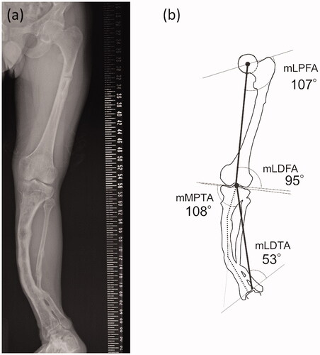
The standing long-leg antero-posterior (AP) radiograph () shows a severe valgus deformity of his left lower leg. The percentage of the mechanical axis (%MA) of his left knee was 98%. The mechanical lateral distal tibial angle (mLDTA) at his left ankle joint was 53 degrees, indicating a severe valgus deformity. The joint orientation angles around the left knee were not so severely deviated, therefore, most of the deformity occurred on the distal side of the tibia ().
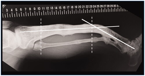
The anatomical axis of his left tibia showed two inflection points in the AP view. The lateral radiograph of his tibia () showed significant anterior bowing, which added another inflection point. We concluded that it would be difficult to plan a surgery to correct these complex deformities in two dimensions.
Figure 2. The standard lateral radiograph of the left lower leg. White solid lines indicate the apparent location of the tibial anatomical axes. Two white dashed lines indicate approximate location of two inflection points in the AP view.
Our 3D surgical planning was performed in three steps: (1) reconstruction of a 3D model of his left tibia and fibula from CT data, (2) placement of three cylinders simulating the intramedullary nail route in line with the three anatomical axes placed within the tibia using 3D modeling software, and (3) virtual corrective osteotomy of the tibia in silico. The workflow diagram of the entire process is shown in .
Figure 3. The schematic diagram showing the overall workflow. The processes for osteotomy planning shown in the gray box were performed by a 3D modeling workstation. IMN: Intramenudally nail.
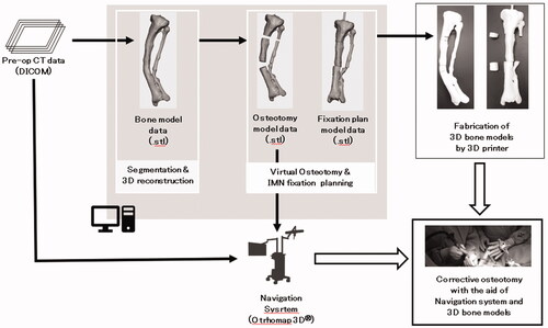
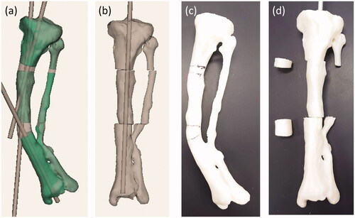
First, the left tibia and fibula of the patient’s lower limb CT data were segmented using 3D slicer [Citation3] and exported as a 3D model in the STL format. Next, using 3D modeling software (Geomagic Sculpt™, Geomagic, Inc. USA), three cylindrical STL data with diameter of 9 mm were created. The STL data of the patient’s lower leg bone was imported into the same working space. One cylinder each was placed in the proximal, diaphyseal and distal parts of the tibia (). The cylinder placed on the most proximal side was placed as perpendicular as possible to the tibial plateau without extruding outside the proximal metaphysis of the tibia. A cylinder passing through the diaphysis was also placed with reference to the anatomical axis so as not to extrude out of the bone. The most distal cylinder was placed so that it passed through the center of the distal diaphysis. Finally, four osteotomy planes were set up on each side of the intersection of the axis of cylinders. By adjusting the position of the two planes that serve as the distal osteotomy surface, it was confirmed that this osteotomy could also correct deformities in the sagittal plane at the same time. After the virtual osteotomy, the anatomical axis of the deformed tibia was normalized by moving the cylinder and the corresponding bone fragment together so that the cylinders were aligned in line with each other (). The position of the fibula osteotomy was set at the same level as the distal tibial osteotomy, considering the position of the neurovascular bundle displaced by the bone deformation. The tibia model data before and after the virtual osteotomy were output as a full-scale model on a fused deposition modeling (FDM) 3D printer (L-DEVO®, Fusion Technology Inc. Japan) ().
Figure 4. (a) The preoperative 3D model data of the left tibia. (b) The postoperative 3D model data of the left tibia. (c) and (d) are photographs of preoperative and postoperative 3D printed model of the tibia, respectively.
Preparation for the surgery
We employed a CT-based navigation system (Orthomap3D®, Stryker Inc. USA) that allows us to reproduce a 3D osteotomy plan in the actual surgery. By digitizing the target bone with a special probe during surgery, the relative position of the surgical machine and the bone can be displayed on the multiplanar CT image (). The surgeon could precisely identify the osteotomy site by using the navigation system to superimpose the planned osteotomy plane on the preoperative tibial CT image.
Figure 5. The screenshot of the navigation system during surgery. Osteotomy planes and post-osteotomy models showing the intramedullary nail route were superimposed on the CT image data of the patient’s tibia.
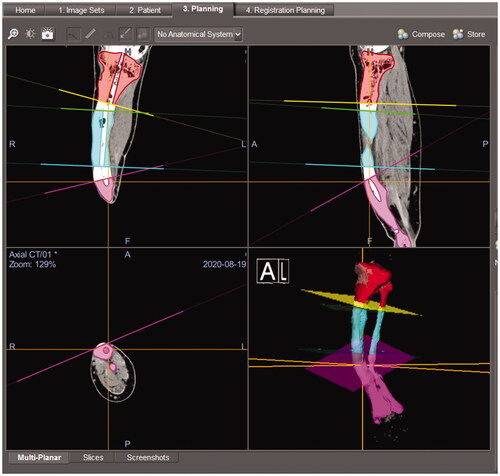
For surgical planning, the three virtually osteotomized tibial models were imported into Orthomap3D® in STL format data. Four reference planes were defined to match the osteotomy plane of the imported model on the navigation system to help the surgeon understand the osteotomy plane in three dimensions during surgery (). Each segment of the tibia models also had an open tunnel for the IMN to indicate the correct route for perforating the closed medullary canal ().
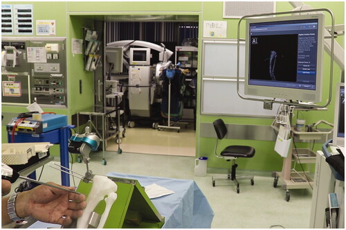
We performed a rehearsal of the navigation surgery to confirm the position of the skin incision and tracker placement with 3D printed preoperative tibia models of the patient’s tibia (). Since the tracker was to be placed on the most proximal fragment of the tibia, it was decided to perform the surgery from the distal osteotomy site. We also found it necessary to employ a suprapatellar approach for IMN placement to avoid interfering with the navigation tracker placed proximal to the tibia. For the subtrochanteric atypical fracture of the ipsilateral femur, we planned antegrade IMN fixation combined with chipping technique [Citation4].
Figure 6. Rehearsal of the navigation system using a patient tibia model.
Surgical treatment
General anesthesia was administered before surgery and a lumbar epidural catheter was placed for intraoperative and postoperative analgesia. First, the patient was placed on a traction table in the supine position, and the operation was performed starting with the IMN fixation for subtrochanteric atypical fracture of the left femur. After placing the antegrade IMN according to the standard procedure, a chipping technique was applied to the fracture to stimulate fracture union [Citation4]. Manual compression of the fracture site along the IMN was performed before the insertion of distal locking screws. After the operation on the femoral side was completed, the patient was transferred to the standard operation table in the supine position.
We first placed the optical tracker of the navigation system at a previously planned location on the proximal tibia. The location and length of two skin incisions for each of the two osteotomy sites were determined with reference to the 3D model of the patient’s tibia. After the exposure of the anterior cortex of the tibia from the skin incision, we performed the surface registration of the tibia using a digitizing probe of the navigation system. This enabled us to display the positional relationship between the tibia and the surgical devices with optical markers in real time.
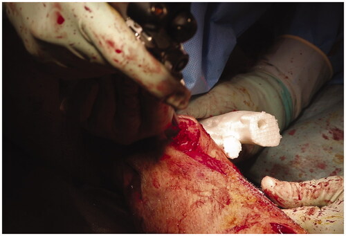
Next, we performed the distal tibial corrective osteotomy under navigation guidance (). Using a high-speed burr with a tracking marker, the position and direction of cutting could be confirmed by the navigation system. From the opening of the distal tibial osteotomy, we performed an osteotomy of the fibula, which lies dorsally to the tibia. Once the osteotomy was complete, the distal bone fragment without the navigation tracker could not be tracked. We therefore located the IMN pathway in the osteotomy cross-section with reference to the 3D bone model and X-ray fluoroscopy, and drilled the closed medullary canal using a high-speed bar and reamer (). The proximal osteotomy was performed in the same way as for the distal side.
Figure 7. (a) Tibial osteotomy using the navigation system. (b) One of the resected bone fragments and a corresponding bone model. The actual resected bone fragments are smaller than the model for the width of the burr bit.
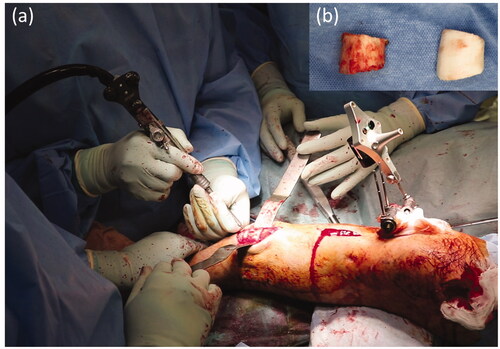
Figure 8. After completion of the osteotomy, we perforated the closed medullary canal visible in the osteotomy cross-section with reference to the bone model and created the intramedullary nail route.
After the entry point was prepared with navigation and an image intensifier assistance, the IMN (T2 alpha tibia®, Stryker Inc. USA) was placed using a suprapatellar approach. The proximal interlocking screws of the IMN were placed first, and we applied manual compression between the fragments. The distal interlocking screws were placed after correct rotation of the foot. The total operation time for both operations was 8 h and 40 min, and the amount of blood loss was 900 mL.
Outcome and follow-up
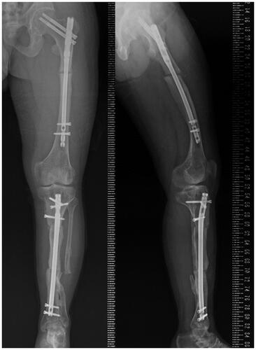
Active and passive range of motion training of the hip, knee, and ankle joints was started immediately after surgery under the guidance of a physiotherapist. Only non-weight-bearing walking was allowed until 4 weeks after surgery, after which protected weight bearing as tolerated was allowed. He was discharged to his home 8 weeks after the surgery after confirming that there was no post-operative infection and that he could move safely with crutches. He could return to the same work he had been doing before the surgery 1 month after his discharge from our hospital. Both the femoral and tibial osteotomy sites had healed at 4 months (). At present, he can work all day long and is not bothered by pain in his left lower leg.
Figure 9. Postoperative long-leg standing radiograph of the left lower leg in antero-posterior and lateral views.
Discussion
We performed a CT-based navigation-assisted corrective osteotomy for complex tibial deformity in a patient with HVDRR. The reconstructed 3D bone model from the CT images was not only used in the navigation system, but also created using a 3D printer for rehearsal of the surgery and for intraoperative reference.
Planning for deformity correction surgery of long bones has traditionally been done in two dimensions based on standard radiographs [Citation5]. However, especially in patients with complex deformities, such as torsional deformities and mixed angular deformities in different planes, there are limitations in performing accurate corrective surgeries with two-dimensional surgical planning. Three-dimensional surgical planning in silico enables us to simultaneously check deformation correction in multiple planes, which helps us to plan surgery that is more accurate and timesaving [Citation6–8]. In addition, on using a 3D printer to output the 3D model data of the affected bone and referring to it, we can better understand the deformation of the bone and the positional relationship between the adjacent bones [Citation6]. A bone model of the healthy side can also be used as a reference during surgery to make corrections, if available [Citation9]. It has also been reported that 3D bone models can be imported into virtual reality systems for orthopedic surgery planning [Citation10]. However, the bone model output as a real entity has the advantage that it can be used for pre-contouring of the fixation plate or for rehearsal of surgical instruments as reported here.
One of the major disadvantages of the navigation system is that it can only track the one bone fragment with the tracker. Therefore, once the osteotomy is complete, it is impossible to track the bone fragments on the separated side. Moreover, due to this disadvantage, the rotation of the ankle joint cannot be assessed intraoperatively with the navigation system. With more than one tracker, it is possible to track several bone fragments simultaneously [Citation11]. However, when the post-osteotomy bone fragment is relatively small, as in this case, it is very difficult to secure the space to insert pins to fix an additional tracker. A method of pose estimation of bone fragments by real-time 2D/3D matching using intraoperative X-ray fluoroscopic images [Citation12] has the potential to overcome the problem of marker placement. This method requires a workstation with high processing power that can perform real-time 2D/3D matching. In addition, if the osteotomy is performed in a different shape from the preoperative plan, the error will affect the matching accuracy.
With the recent decrease in the price of 3D printers, the use of 3D models to support surgery has become an accessible option. The combined use of a 3D bone model after completion of the osteotomy for reference can complement such disadvantage of the navigation system without additional expensive equipment or systems. The combined use of a 3D bone model after completion of the osteotomy for reference can complement such disadvantage of the navigation system without additional expensive equipments or systems. Especially, in the present case, the 3D bone model that could be referred to intraoperatively was also very useful in creating the IMN route after completion of the osteotomy.
Conclusion
The combined use of the navigation system and the 3D model was useful to conduct corrective osteotomy for complex deformities. The navigation system provides an accurate 3D understanding of the position and angle of the osteotomy. The patient-specific 3D bone model can be referred to when performing additional procedures on the separated bone fragments after the osteotomy, which the navigation system can no longer track.
Disclosure statement
No potential conflict of interest was reported by the author(s).
References
- Haffner D, Emma F, Eastwood DM, et al. Clinical practice recommendations for the diagnosis and management of X-linked hypophosphataemia. Nat Rev Nephrol. 2019;15(7):435–455.
- Sharkey MS, Grunseich K, Carpenter TO. Contemporary medical and surgical management of X-linked hypophosphatemic rickets. J Am Acad Orthop Surg. 2015;23(7):433–442.
- Fedorov A, Beichel R, Kalpathy-Cramer J, et al. 3D slicer as an image computing platform for the Quantitative Imaging Network. Magn Reson Imaging. 2012;30(9):1323–1341.
- Watanabe Y, Matsushita T. Femoral non-union with malalignment: reconstruction and biological stimulation with the chipping technique. Injury. 2016;47(Suppl 6):S47–S52.
- Paley D, Herzenberg JE, Tetsworth K, et al. Deformity planning for frontal and sagittal plane corrective osteotomies. Orthop Clin North Am. 1994;25(3):425–465. Jul
- Jastifer JR, Gustafson PA. Three-dimensional printing and surgical simulation for preoperative planning of deformity correction in foot and ankle surgery. J Foot Ankle Surg. 2017;56(1):191–195.
- Mishra A, Verma T, Vaish A, et al. Virtual preoperative planning and 3D printing are valuable for the management of complex orthopaedic trauma. Chin J Traumatol. 2019;22(6):350–355.
- Dobbe JG, Pre KJ, Kloen P, et al. Computer-assisted and patient-specific 3-D planning and evaluation of a single-cut rotational osteotomy for complex long-bone deformities. Med Biol Eng Comput. 2011;49(12):1363–1370.
- Wei YP, Lai YC, Chang WN. Anatomic three-dimensional model-assisted surgical planning for treatment of pediatric hip dislocation due to osteomyelitis. J Int Med Res. 2020;48(2):300060519854288.
- Zaragoza-Siqueiros J, Medellin-Castillo HI, de la Garza-Camargo H, et al. An integrated haptic-enabled virtual reality system for orthognathic surgery planning. Comput Methods Biomech Biomed Eng. 2019;22(5):499–517.
- Pflugi S, Vasireddy R, Lerch T, et al. Augmented marker tracking for peri-acetabular osteotomy surgery. Int J Comput Assist Radiol Surg. 2018;13(2):291–304.
- Grupp RB, Hegeman RA, Murphy RJ, et al. Pose estimation of periacetabular osteotomy fragments with intraoperative X-Ray navigation. IEEE Trans Biomed Eng. 2020;67(2):441–452.