
Abstract
A reliable method for precise perforator mapping can be extremely valuable in perforator flap surgery. In this study, we attempted to map perforator location using 3-dimensional computed tomography angiography (CTA), a newly developed application, and a tablet device. Preliminary examinations to test the device were conducted in mini-pigs. We used 5 female mini-pigs. Preoperative imaging of the vasculature was undertaken with CTA in the prone position, following Iopamidol (200 ml) injection via the internal jugular vein. Prior to the examination, we placed round markers on the backs of the mini-pigs. To assess accuracy, we compared the perforator positions acquired with an optical position measurement device with the perforator positions acquired with the tablet device. Furthermore, we compared the perforator positions with the tablet navigation device, which we measured directly. We measured 12 perforators with the optical position measurement device. The mean difference was 10 mm (minimum, 2 mm; maximum, 20 mm). We measured these perforators with the tablet navigation device. The mean difference was 5.4 mm (minimum, 0 mm; maximum, 20 mm). The perforator flaps were elevated safely. The perforator flaps could be elevated safely using our device, as the mean difference was only 10 mm, which is acceptable for navigating perforator flap operations. Pig backs are triangular in shape; therefore, we were unable to place markers on the contralateral side. Thus, for clinical applications of the device, we should determine the ideal marker locations.
Introduction
In the past two decades, perforator flaps have been commonly used in reconstructive surgeries to reduce postoperative complications. When raising perforator flaps, it is necessary to dissect the vascular structure meticulously, mainly because of their irregular anatomical vascular distribution [Citation1,Citation2]. To avoid damaging the vasculature of perforator flaps, it is important for surgeons to confirm where suitable perforators are located and to understand the underlying vessel structure by performing preoperative medical imaging. Several imaging methods have recently been utilized for preoperative surgical assessment and planning. Hand-held Doppler ultrasound, color Doppler ultrasound, computed tomography angiography (CTA), and magnetic resonance angiography (MRA) [Citation3–6] are widely used to determine vascular variations in patients.
The appropriate use of medical imaging ensures patient safety. However, it is sometimes not possible to make a rapid decision regarding whether to cut deeply into tissues. In such cases, it is necessary to take the eyes off the patient undergoing surgery and watch their medical images.
To overcome these challenges, we have developed a new device using augmented reality. Augmented reality has already been introduced for surgical navigation systems in the medical field [Citation7]. We built our device based on data from several studies that had previously created an overlay surgical navigation system using a tablet PC and 3D image technology [Citation8,Citation9]. This novel device allows us to recognize vascular structures within the operative field. Detection of three fiducial markers permits overlaying of vascular images on the screen of the tablet device. In the present study, we propose the use of a navigation system to visualize perforators on a tablet device that can be used in conjunction with CTA for detailed three-dimensional (3D) image reconstruction. Using this system, we could locate the perforator position and course and identify the main vessels during the operation. Augmented reality (AR) navigation systems have recently been introduced for plastic surgery. These utilize smartphones to visualize perforators instead of tablet devices [Citation10,Citation11]. Vascular images are fixed against landmarks such as the umbilicus, anterior superficial iliac spine, pubic symphysis, lateral malleolus, or tibial border. These systems are, therefore, markerless imaging registries.
By contrast, our system uses three markers for the registration process. Thanks to this system, we do not need to fix any anatomical landmarks. Using a tablet device instead of a smartphone allows for the visualization of clearer and larger images.
Herein, we report our experience using this device on animals. The results of the comparison between the navigational accuracy of our device and that of a conventional optical measurement device are described below.
Design and methods
Animals
This study was approved by the Tokyo Women’s Medical University animal care committee. Healthy female mini-pigs were selected. The mini-pigs were fasted overnight before being anesthetized with a single intramuscular injection of ketamine and medetomidine. During CTA and surgery, isoflurane-maintained anesthesia and artificial ventilation were monitored by veterinarians.
Computed tomography scanning technique
Following catheterization of the left jugular vein and the attachment of. CT scanner skin markers (IZI Medical Products Inc., MD, USA), which were placed onto the surface of the skin at 50-mm intervals prior to image acquisition, CTA and the surgical procedure were conducted with the animal in the prone position. CTA was performed using a 16-detector-row CT scanner (BrightSpeed Elite; General Electric, Milwaukee, WI, USA). The scans were performed using the following parameters: 0.37-s gantry rotation speed, 0.50-mm collimator width slice thickness, and 1.37 helical detector pitch. The X-ray tube voltage was 120 kV, and the tube current ranged from 118 to 151 mA. All scanning procedures were performed after intravenous administration of 200 ml of nonionic iodinated contrast medium at a concentration of 370 mg/ml (Iopamilon 370; Bayel, Tokyo, Japan). The contrast material was injected at a rate of 4 ml/s via an 18-g intravenous catheter inserted into the left jugular vein. The scanning delay was 10 s.
3D vascular model construction
CT data were stored as Digital Imaging and Communications in Medicine (DICOM)-compatible files on a CD-ROM and were loaded onto a personal computer. Based on the CT images, we performed a 3D reconstruction of the perforators located between the base of the large vessels and fascia using 3D Slicer [Citation12], which is a free open-source software application for medical image computing.
Device and mechanism of a navigation system
The navigation system used in this study consisted of a tablet device (iPad 2®, Apple Inc. CA, USA), CT scanner skin markers, and plastic marker caps () [Citation8,Citation9]. Following navigation, our custom-made software was installed on a tablet device. We selected three skin markers around the perforator and covered them with plastic marker caps (). The tablet device recognized these marker caps and generated the coordinate system of the pig’s camera image using the rear camera of the tablet device. The coordinate system of the 3D CTA image () was calculated from the corresponding markers and merged with the two coordinate systems. We developed an algorithm that determines the marker coordinate position with respect to a monocular camera using placement information of three markers (distance between points) and size information of the marker itself (marker diameter), thereby enabling us to grasp 3D position information, even from the monocular camera on the back of the iPad. Finally, it displayed the 3D vasculature model of the CTA image from the camera of the tablet device. We observed the position and posture of the perforator on the tablet device using skin imaging ().
Figure 1. Components of the navigation system: a tablet device (iPad 2® Apple Inc., CA, USA), CT-compatible markers, and plastic marker caps.
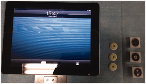
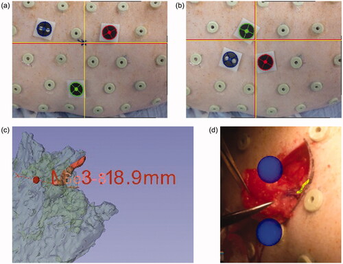
Figure 2. Screens during surgical navigation: the yellow object indicates a vascular structure. (a) Preoperative view of the tablet using a small triangle. Red and yellow crosses indicate perforator positions at the level of emergence from the fascia; (b) preoperative view of the tablet using a large triangle; (c) a 3D perforator image using a 3D slicer; (d) intraoperative view of the navigation system.
Examination
Appropriate marker formation
All animals underwent a preoperative CTA scan, as previously described, within 1 week before the planned surgical procedure. After CT scanning, the CT scanner skin markers were retained until surgery to maintain the fiducial positions. We selected perforators that were larger than 1 mm, which were suitable for our study, and placed three markers around these perforators.
To determine the appropriate selection of markers, we used the following two methods. First, we selected three markers that formed a small triangle around the perforator with a length of 50 mm on each side. Second, we selected markers that formed a larger triangle with a length of 100 mm on each side (). Before starting the operation, we marked the emerging locations of the navigated perforators on the skin using different marker formations. The perforators were dissected through a 10-cm incision. We then intermittently observed the course of the vessels, as visualized on the tablet during surgery. After identifying the perforators, we measured the gaps between the preoperative markings and the locations of the perforators.
Comparison between our device and a conventional navigation device
An optical position measurement device is both accurate and the prevailing choice in the field of navigation devices [Citation13,Citation14]. To confirm that our device is as useful as a commercial navigation device, we measured the perforator and fiducial marker locations using an optical position measurement device (Polaris spectra® Northern Digital Inc., ON, Canada). The optical instrument calculated the fiducial localization error from the data from the three benchmark markers and the target registration error from the perforator data [Citation15,Citation16], based on a 3D image of the animal that was constructed at the beginning of the measurement.
Statistical analysis
All data were analyzed using the SPSS software package (version 20.0; SPSS Inc., Chicago, IL, USA). Comparisons of numerical data between groups of patients were performed using Student’s t-test. Continuous data are expressed as mean ± standard deviation (SD). A p-value of <0.05 was considered to indicate statistical significance.
Results
Animal characteristics
From April 2013 to August 2014, three female mini-pigs (20–21 kg) were selected for this study. In total, the navigation of 18 perforators using our tablet device was planned preoperatively.
CT angiography and perforator images
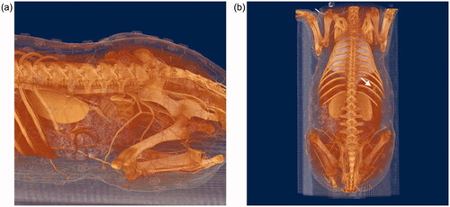
All animals were successfully subjected to CT scanning. 3D CT images showed that there were numerous perforators from the intercostal and internal iliac arteries on the backs of the animals ().
Figure 3. 3D vascular structures based on CT images. Based on the data, we selected perforators to be used in our experiment. (a) Lateral view; (b) dorsal view.
Accuracy of perforator detection
We dissected 18 perforators. All the perforators could be successfully identified with our device. However, the data for six of the perforators assessed with an optical position measurement device were lost due to technical issues. Therefore, the result with the tablet PC was generated from the data of 18 perforators, and the result with Polaris was generated from the data of 12 perforators.
To analyze the appropriate arrangement of fiducial markers, we measured the difference between the actual locations of the perforators and the locations shown on the tablet device with a small triangle and a large triangle marker position (). Although the abdominal-to-ventral distances were significantly different between the groups (p < 0.05), there was no difference in the head-to-tail and direct distances (p = 0.39). On the other hand, we observed direct distance differences of 4.33 ± 3.66 mm with the use of smaller triangular markers. Furthermore, using the larger triangles, we observed differences of 6.02 ± 5.02 mm. There was no significant difference between the groups (p = 0.26). We confirmed that the formation of a large triangular marker was effective.
Table 1. Errors of tablet device navigation system registered by small and large triangles.
To assess the accuracy of the navigation through the tablet device, we measured the difference between the locations of the actual perforators and the locations of the perforators using a conventional optical measurement instrument (). The mean difference of the target registration error was 10.8 ± 6.93 mm. In addition to the location of the perforators, we measured the accuracy of the location of the markers and found that the mean difference for fiducial localization error was 3.76 ± 5.07, 2.38 ± 2.14 and 2.80 ± 2.3 mm. These results show that our device is not inferior to conventional navigation devices.
Table 2. Coordination measured by optical tracking system (mm).
Discussion
In the present study, we evaluated the use of a tablet device system for navigation during perforator flap surgery. We utilized this method in mini-pigs instead of humans, as porcine models have previously been used in flap surgeries [Citation17], and microvascular flap surgeries are more commonly evaluated in pigs [Citation18,Citation19]. Thus, previous studies have offered some insight into the perforator characteristics of pigs. Taylor et al. found that the vessels in the regions of the shoulder and hip joints and adjacent to the dorsal midline are larger than those in any other location in pigs [Citation20]. Mei et al. previously reported that the lateral branches of the intercostal artery are good choices when evaluating perforator flap surgery in mini-pig models. This report was based on CTA data following jugular vein administration of 6% gelatin and lead oxide to exsanguinated Guangxi Bama mini-pigs [Citation21]. Our CTA data with nonionic iodinated contrast medium were compatible with their findings and perforator selection. Our data showed that perforators from the intercostal and internal iliac arteries were sufficiently large to be used in our study.
Reports have increasingly discussed perforator mapping by using various instruments. For instance, the use of Doppler ultrasound, MRA and CTA has been frequently reported. Recently, dynamic infrared thermography, indocyanine green fluorescence imaging, and imaging-guided stereotactic navigation systems have been used for perforator mapping [Citation22–25]. In addition, several articles have discussed perforator navigation systems that use computer software in combination with CTA data [Citation24,Citation26]. These prior reports indicated that while the method is reliable, it cannot be used intraoperatively. Instead, our device can be used during the operation to confirm the perforator location. However, our device showed artificial 2D vascular images on a tablet. Thus, if the position of the perforator needs to be visualized in real-time, indocyanine green fluorescent imaging [Citation22] or digital subtraction angiography [Citation27] should be used.
In augmented reality, it is important to grasp space using stereoscopic vision. In contrast, although this system provides planar information, it is possible to grasp the space using dynamic parallax by moving the screen left and right. Moreover, stereoscopic vision can impose a burden on the surgeon during surgery, as it includes wearing a head-mounted display on the head. Therefore, our navigation system is considered to be simple and advantageous.
The mean average error rate using our navigation device was approximately 5 mm, while the mean average error assessed using the optimal measurement device was 10 mm. This indicates that our device is as accurate as a conventional measurement device. However, the average error rate in a previous report is 0.5 mm by using the optimal measurement device to identify the perforator location [Citation24]. Our target registration error was larger than that reported previously. The fiducial localization errors were approximately 3 mm. The upper and lower legs of mini-pigs were easily abducted when they were placed in the prone position. However, it was difficult to place mini-pigs in the same position during the operation, as that during CT. We believe that the 3D animal image registration encountered an error, which affected the target registration errors. However, we could dissect perforators with a 5-mm error using our device. The anterior lateral thigh flap perforators existed in a 3-cm circle [Citation28]. The microsurgeon identified perforators of the anterior lateral thigh flap intraoperatively. We assume that a 5-mm gap is acceptable for navigating perforators to elevate the perforator flaps.
We used small and large triangular marker positions to navigate the vascular images on the tablet device. Even though the gap in the markers was 10 cm, the accuracy of the navigation was equal to that of the small-triangle group. When we preoperatively set the marker positions, we placed three markers 10 cm apart. Perforators were easily detected using the proposed device. We considered a 1-cm error permissible prior to this study. The maximum errors of our device were within 1 cm. We believe that our level of acceptable accuracy for perforator targeting is suitable. Our navigation device system was precise both preoperatively and intraoperatively in a mini-pig. We believe that this method will also be useful in human operations.
Thus, perforator navigation systems that use computer software combined with CTA data can be used for preoperative perforator mapping. We can place a perforator marking on the patient’s body, instead of using a hand-held Doppler (HHD) ultrasound and color Doppler ultrasound (CDU). Marking perforators with hand-held Doppler ultrasound and color Doppler ultrasound takes a long time [Citation5]. Our system shows the location of the perforator within a few seconds. This AR navigation device, therefore, reduces the examination time. Lethaus et al. reported that the sensitivity and positive predictive value for identifying perforators on the thigh were 97.9% and 100% for CDU and 90.5% and 80.4% for HHD [Citation29]. A review paper summarizes the comparison between CDU and CTA for preoperative anterolateral thigh flap perforator imaging [Citation30]. CDU provides greater preoperative perforator imaging sensitivity than CTA (95.3% and 90.4%, respectively). However, the false-positive rates for CDU were marginally higher than those for CTA (2.8% and 2.4%, respectively). They are not as accurate as CTA [Citation31].
Our navigation system that is based on CTA images is reliable and allows for quick observation of perforator positions as compared with HHD and CDU. Moreover, we can access the CTA data on the iPad to better explain the surgical procedures to the patients and their families. It is also easy for medical staff and residents to evaluate data using a tablet device because they are intuitively able to understand a vascular image.
Recently, AR technology has been incorporated into the field of plastic surgery to indicate perforator locations. The navigation system is divided into three systems, projection-mapping [Citation11,Citation32,Citation33], a medical image overlay system with smart glasses [Citation34–36] and a smartphone [Citation10,Citation11]. The following are the navigation system’s target vasculatures: the deep inferior epigastric artery, the lateral circumflex femoral artery, the superficial circumflex iliac artery, the posterior tibial artery and the peroneal artery. Yodrabum et al. established a device similar to ours. They assessed the accuracy of their device by analyzing how accurately it identified perforator locations, compared with a duplex scan. The inaccuracy was 0.7–1.0 cm [Citation11] and the error was larger than our target registration errors.
However, this device has some limitations. One disadvantage is that three markers are required to overlay the vascular image on a tablet device. One of the specific anatomical portions, namely the umbilicus and nipples for fiducial points, can be set; otherwise, the patients need to keep the markers on their skin or draw circles around the marker every day until the operation. In this study, we used CTA DICOM data to show perforators and vascular pedicles. One of the disadvantages of CTA is radiation exposure. Even though the radiation exposure is reduced compared with that in the conventional CT scan [Citation37], we might need to select MRA to reduce the risks of radiation exposure.
In conclusion, in the present study, we were able to safely elevate perforator flaps during all procedures performed in mini-pigs using our tablet navigation device system. The observed difference between the actual location and that shown on the device was only 10 mm, which is within the acceptable range for navigating perforator flap surgery.
Disclosure statement
No potential conflict of interest was reported by the author(s).
Additional information
Funding
References
- Kimata Y, Uchiyama K, Ebihara S, et al. Anatomic variations and technical problems of the anterolateral thigh flap: a report of 74 cases. Plast Reconstr Surg. 1998;102(5):1517–1523.
- Rozen WM, Ashton MW, Grinsell D. The branching pattern of the deep inferior epigastric artery revisited in-vivo: a new classification based on CT angiography. Clin Anat. 2010;23(1):87–92.
- Yu P, Youssef A. Efficacy of the handheld Doppler in preoperative identification of the cutaneous perforators in the anterolateral thigh flap. Plast Reconstr Surg. 2006;118(4):928–933. discussion 934–925.
- Su W, Lu L, Lazzeri D, et al. Contrast-enhanced ultrasound combined with three-dimensional reconstruction in preoperative perforator flap planning. Plast Reconstr Surg. 2013;131(1):80–93.
- Rozen WM, Phillips TJ, Ashton MW, et al. Preoperative imaging for DIEA perforator flaps: a comparative study of computed tomographic angiography and Doppler ultrasound. Plast Reconstr Surg. 2008;121(1):9–16.
- Fukaya E, Saloner D, Leon P, et al. Magnetic resonance angiography to evaluate septocutaneous perforators in free fibula flap transfer. J Plast Reconstr Aesthet Surg. 2010;63(7):1099–1104.
- Kong SH, Haouchine N, Soares R, et al. Robust augmented reality registration method for localization of solid organs’ tumors using CT-derived virtual biomechanical model and fluorescent fiducials. Surg Endosc. 2017;31(7):2863–2871.
- Mochizuki Y, Hosaka A, Kamiuchi H, et al. New simple image overlay system using a tablet PC for pinpoint identification of the appropriate site for anastomosis in peripheral arterial reconstruction. Surg Today. 2016;46(12):1387–1393.
- Kamiuchi H, Masamune K. Medical image overlay system with a tablet PC and three markers. IEICE Tech Rep. 2012;112(200):29–34.
- Pereira N, Kufeke M, Parada L, et al. Augmented reality microsurgical planning with a smartphone (ARM-PS): a dissection route map in your pocket. J Plast Reconstr Aesthet Surg. 2019;72(5):759–762.
- Yodrabum N, Rudeejaroonrung K, Chaikangwan I, et al. Precision of low-cost augmented reality in prefabricated cutting guide for fibular free flap surgery. J Craniofac Surg. 2022;33(3):916–919.
- Fedorov A, Beichel R, Kalpathy-Cramer J, et al. 3D slicer as an image computing platform for the quantitative imaging network. Magn Reson Imaging. 2012;30(9):1323–1341.
- Wiles AD, Thompson DG, Frantz DD. Accuracy assessment and interpretation for optical tracking systems. Paper presented at: Medical Imaging, 5 May, 2004; San Diego, CA; 2004.
- Elfring R, de la Fuente M, Radermacher K. Assessment of optical localizer accuracy for computer aided surgery systems. Comput Aided Surg. 2010;15(1–3):1–12.
- Fitzpatrick JM, West JB, Maurer CR. Jr. Predicting error in rigid-body point-based registration. IEEE Trans Med Imaging. 1998;17(5):694–702.
- Fitzpatrick JM, West JB. The distribution of target registration error in rigid-body point-based registration. IEEE Trans Med Imaging. 2001;20(9):917–927.
- Stell PM. The pig as an experimental model for skin flap behaviour: a reappraisal of previous studies. Br J Plast Surg. 1977;30(1):1–8.
- Villamaria CY, Rasmussen TE, Spencer JR, et al. Microvascular porcine model for the optimization of vascularized composite tissue transplantation. J Surg Res. 2012;178(1):452–459.
- Katz RD, Rosson GD, Taylor JA, et al. Robotics in microsurgery: use of a surgical robot to perform a free flap in a pig. Microsurgery. 2005;25(7):566–569.
- Taylor GI, Minabe T. The angiosomes of the mammals and other vertebrates. Plast Reconstr Surg. 1992;89(2):181–215.
- Mei J, Yin Z, Zhang J, et al. A mini pig model for visualization of perforator flap by using angiography and MIMICS. Surg Radiol Anat. 2010;32(5):477–484.
- Azuma R, Morimoto Y, Masumoto K, et al. Detection of skin perforators by indocyanine green fluorescence nearly infrared angiography. Plast Reconstr Surg. 2008;122(4):1062–1067.
- de Weerd L, Weum S, Mercer JB. The value of dynamic infrared thermography (DIRT) in perforatorselection and planning of free DIEP flaps. Ann Plast Surg. 2009;63(3):274–279.
- Rozen WM, Ashton MW, Stella DL, et al. Stereotactic image-guided navigation in the preoperative imaging of perforators for DIEP flap breast reconstruction. Microsurgery. 2008;28(6):417–423.
- Sheena Y, Jennison T, Hardwicke JT, et al. Detection of perforators using thermal imaging. Plast Reconstr Surg. 2013;132(6):1603–1610.
- Pacifico MD, See MS, Cavale N, et al. Preoperative planning for DIEP breast reconstruction: early experience of the use of computerised tomography angiography with VoNavix 3D software for perforator navigation. J Plast Reconstr Aesthet Surg. 2009;62(11):1464–1469.
- Ohjimi H, Era K, Fujita T, et al. Analyzing the vascular architecture of the free TRAM flap using intraoperative ex vivo angiography. Plast Reconstr Surg. 2005;116(1):106–113.
- Steve AK, White CP, Alkhawaji A, et al. Computed tomographic angiography used for localization of the cutaneous perforators and selection of anterolateral thigh flap “Bail-Out” branches. Ann Plast Surg. 2018;81(1):87–95.
- Lethaus B, Loberg C, Kloss-Brandstatter A, et al. Color duplex ultrasonography versus handheld Doppler to plan anterior lateral thigh flaps. Microsurgery. 2017;37(5):388–393.
- Moore R, Mullner D, Nichols G, et al. Color Doppler ultrasound versus computed tomography angiography for preoperative anterolateral thigh flap perforator imaging: a systematic review and meta-analysis. J Reconstr Microsurg. 2021; doi:10.1055/s-0041-1740958.
- Scott JR, Liu D, Said H, et al. Computed tomographic angiography in planning abdomen-based microsurgical breast reconstruction: a comparison with color duplex ultrasound. Plast Reconstr Surg. 2010;125(2):446–453.
- Cifuentes IJ, Dagnino BL, Salisbury MC, et al. Augmented reality and dynamic infrared thermography for perforator mapping in the anterolateral thigh. Arch Plast Surg. 2018;45(3):284–288.
- Fitoussi A, Tacher V, Pigneur F, et al. Augmented reality-assisted deep inferior epigastric artery perforator flap harvesting. J Plast Reconstr Aesthet Surg. 2021;74(8):1931–1971.
- Nuri T, Mitsuno D, Iwanaga H, et al. Application of augmented reality (AR) technology to locate the cutaneous perforator of anterolateral thigh perforator flap: a case report. Microsurgery. 2022;42(1):76–79.
- Wesselius TS, Meulstee JW, Luijten G, et al. Holographic augmented reality for DIEP flap harvest. Plast Reconstr Surg. 2021;147(1):25e–29e.
- Pratt P, Ives M, Lawton G, et al. Through the HoloLens looking glass: augmented reality for extremity reconstruction surgery using 3D vascular models with perforating vessels. Eur Radiol Exp. 2018;2(1):2.
- Masia J, Clavero JA, Larranaga JR, et al. Multidetector-row computed tomography in the planning of abdominal perforator flaps. J Plast Reconstr Aesthet Surg. 2006;59(6):594–599.