
 ?Mathematical formulae have been encoded as MathML and are displayed in this HTML version using MathJax in order to improve their display. Uncheck the box to turn MathJax off. This feature requires Javascript. Click on a formula to zoom.
Abstract
Compact turbines offer potential to reduce hydropower plant construction costs, but conventional turbine blade designs endanger entrained fish due to high blade strike speeds and thin leading edges. We evaluated the potential for combined blade leading edge slant and large leading edge thickness to increase strike survival. Rainbow trout (Oncorhynchus mykiss) were subjected to strikes with 100 mm thick blade analogues. At 10 m/s, strikes at fish length to blade leading edge thickness ratio (L/t) of 2 resulted in 98% survival at a location along the blade witha 30° slant relative to the tangential direction, compared to 26.8% survival at a location with 90°slant. For L/t 1.14-2, survival was found to be sensitive to location of strike within the mid-body region, determined from high-speed video. Strikes of 200 mm fish at 10 m/s resulted in 68% survival when body strike location was 0.58 (near caudal), and 7.9% when body strike location was 0.36 (near head). These results are consistent with previous trends and indicate opportunities to improve turbine blade design for greater entrained fish survival at higher turbine speeds, at both low head (<30 m) and high head projects.
1. Introduction
The potential for negative impacts of hydropower dams on downstream migrating fish is a major issue being addressed by natural resource managers and project owners worldwide. For diadromous species, migratory delays and injury and mortality associated with dam passage may reduce the fitness and survival of individual fish and contribute to declines of affected populations (Moring Citation2005; Brown et al. Citation2013). In addition to the development and application of downstream passage technologies designed to reduce turbine entrainment and provide safe, timely, and effective egress past hydropower projects, turbine designs that reduce the potential for injury and mortality of entrained fish have been developed to achieve high project survival rates with lower economic and operational impacts to power generation (Hogan et al. Citation2014). More specifically, several “fish-friendly” turbine technologies have been developed for low-head dams (less than 10 m of head) as a means to improve environmental performance at existing projects by means of turbine retrofits, or to promote environmentally sustainable development at existing non-powered dams or other new projects (Hogan et al. Citation2014).
If effective, fish-safe turbines could provide an alternative to costly fish protection strategies at hydropower facilities, including mechanical screening of small fish from hydropower intakes and operational constraints such as nightly shutdowns during peak migration seasons. While bar racks are sufficient to prevent large fish and debris from entering a turbine, narrow-spaced bar screens or racks with 1-inch clear spacing or smaller may be required to prevent entry of small or early life stages of fish into the turbine (Turnpenny Citation1981; NMFS Citation2011; USFWS Citation2017). Fine screens impose a head loss at generating facilities, and require control and cleaning systems to operate with high frequency (Francfort et al. Citation1994). The sum of capital costs, generation losses, and operating costs incurred with a fine mesh fish screen can render hydropower projects economically infeasible.
While there is an economic incentive to design turbines for safe through-turbine passage, blade strike injury of fish passing through turbines in the field is not easily observed or controlled. The injury mechanisms to which fish are exposed when they pass through turbines have been evaluated in laboratory settings in recent years (Turnpenny et al. Citation1992; Turnpenny Citation1998; EPRI Citation2008, Citation2011; Bevelhimer et al. Citation2017). In general, the primary source of injury and mortality for fish entrained in turbines operating at low head is collision with the leading edge of turbine blades (Franke et al. Citation1997). Conventional low head small hydropower turbine designs are often characterized by high rotational speeds, high strike velocities (i.e. relative velocity of fish to approaching blade), and thin leading edges. These factors contribute to higher strike probabilities and mortality (Amaral et al. Citation2018). Testing at the Alden linear strike facility (EPRI Citation2008, Citation2011) as well as similar strike work conducted at Oak Ridge National Laboratory (Bevelhimer et al. Citation2017, Citation2019) has shown that thicker blades, particularly with a fish length to blade thickness ratio (L/t) of 2 or below, are associated with higher strike survival.
To assess the dynamics of fish strike and estimate injury and survival at relatively high strike speeds for thick, slanted blades with L/t ratios of approximately 1.4 and 2, strike testing was conducted at the Alden Laboratory linear strike facility. The effects of various leading edge slant angles representative of a thick, curved blade geometry on strike survival were compared to a thick, straight blade geometry.
1.1. Design of a blade with thick slanted leading edge and implications for improved strike survival
The Restoration Hydro Turbine (RHT) developed by Natel Energy features a runner geometry that is designed to enable safe downstream passage of small to moderate size fish that access the turbine by passing through standard, wide-spaced bar racks. Because relative velocities (i.e. fish strike velocities) are highest at the tip for any turbine, the RHT runner blade was designed with a progressively acute slant angle near the blade tip (). The slant angle is expected to reduce the amount of force imparted on a fish struck by the turbine blade in the high-speed region by enabling a glancing contact, rather than direct collision.
Figure 1. Diagram of RHT runner with slanted blade leading edge, with shallow slant angle θh at the hub, acute slant angle θt at the tip, and intermediate slant angle θm at the meridion.
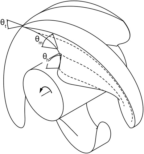
Additionally, the RHT is designed with thick leading edges in order to result in L/t ratios of 2 or less for fish with body lengths up to 400 mm (i.e. maximum size of fish typically entrained at hydro projects utilizing bar racks with clear spacing of approximately 50 mm, excepting eels). The RHT is designed with a low number of blades to reduce the probability of strike.
2. Methods
2.1. Test blades
A 3 D-printed blade analogue was used to represent the leading edge curvature of the RHT runner. The RHT analogue had a 100 mm thick semicircular leading edge and a forward slant which progressed from nearly 90° at the hub, to 30° at the tip. This analogue provided the range of leading edge slant angles present in the RHT runner (). The analogue RHT blade was symmetric about its chord line to eliminate any hydraulic lift that would need to be reacted at the cart mount, unlike actual runner blades which twist from hub to tip.
Figure 2. Schematic of RHT (front) and EPRI (back) analogue blades, noting slant angle strike locations.
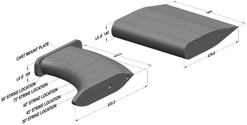
A blade with a straight-edged, 100 mm thick semicircular leading edge, referred to as the EPRI analogue blade, was also tested. This was the same blade that was used in past strike testing at Alden Laboratory (EPRI Citation2008, Citation2011), and had a 90° slant angle across its full length ().
2.2. Test conditions
The RHT analogue blade was tested at strike velocities of 7 m/s, 10 m/s, and 12 m/s (). The EPRI analogue blade was tested at 10 and 12 m/s strike velocities. Most test conditions consisted of 50 to 100 fish strikes, although some had smaller sample sizes due to the limited quantity of fish available.
Table 1. Summary of strike conditions and results for Rainbow trout struck with 100-mm thick blade analogues.
Rainbow trout (Oncorhynchus mykiss) were selected as the test species for the study because they are representative of many salmonids and other boney fishes commonly entrained at hydropower projects, are readily available from commercial hatcheries in a wide range of sizes, and were extensively tested during previous blade strike studies (Turnpenny et al. Citation1992; EPRI Citation2008, Citation2011; Bevelhimer et al. Citation2017, Citation2019). To investigate the effect of slant angle, the RHT analogue blade was tested with strikes occurring at locations along its leading edge corresponding to slant angles of 30°, 45°, 60°, 75°, and 90°. Strikes with the EPRI analogue blade took place halfway along its leading edge.
Approximately 1700 fish were tested. Two groups of fish size were evaluated: small fish with length ranging from 110 to 163 mm, and larger fish with length ranging from 182 to 236 mm. The two size groups corresponded to average L/t ratios of roughly 1.4 and 2 for the blades tested. Strike and control tests took place over a period of 11 weeks from May through July, 2019. Two deliveries of fish from the hatchery, each containing both fish size groups, were used over the course of testing.
2.3. Blade strike test facility
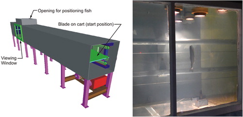
The blade strike test tank, which was initially constructed for the EPRI 2008 studies, was 0.9 m in cross section and about 16.5 m in length, with a 1.2 m square opening at the top utilized to access the location where test fish were fixtured prior to strike (). Visual observation, including high speed video recording of the strikes was possible from this top opening, as well as from windows on the side and bottom of the tank, centered about the strike location. The test blades were mounted to a cart which was propelled by a cable and winch system along rails mounted to the rear wall of the test tank. The cable drive shaft was connected to a clutch, brake, transmission, and main drive motor using v-belts. Blade speed and direction were controlled using a variable frequency drive controller (VFD) connected to a 20-horsepower motor. A clutch and brake were used to start and stop the cart. Strike speed was measured using light sensors mounted on the test tank back wall, which detected the passing of the cart.
Figure 3. Schematic of blade strike test apparatus (left image) and fish position for a blade strike (right image; blades move from through the test apparatus from right to left).
2.4. Test procedures
Testing procedures followed those used in previous strike studies at the Alden facility (EPRI Citation2008, Citation2011). For each treatment and control test, a fish was randomly selected from a holding tank, measured, and placed in an anesthetic bath (1 part eugenol and 9 parts ethanol) for 1 to 2 minutes. When the fish was adequately anesthetized, separate tethers made of fishing line were tied around the caudal peduncle, and through one of the gills and mouth. The fish was then vertically positioned at the strike location by affixing the free ends of the fishing lines in slitted foam blocks located at the bottom (caudal line) and top (head line) of the test tank (). The tethers provided enough tension to keep the fish in place prior to blade approach, but allowed the fish to move freely during and after the strike. Fish were positioned at a 90° angle to the blade, with the upper end of the dorsal fin visually aligned to a marker line on the fish insertion tool representing the centerline of the blade. This positioning ensured that all strikes occurred near the midsection of the fish. The side of the fish that was struck (i.e. ventral, dorsal, or lateral) was also recorded, but could not be controlled due to the rotational degree of freedom of the fish about its tether.
Immediately after strike, (or, for controls, an equivalent period of time in the strike tank), the fish was removed with a dipnet. A uniquely numbered Floy tag was attached at the dorsal fin to allow for identification of any delayed mortalities during the 48-hour post-test holding period. The fish was then examined for external injuries and scale loss. Photographs were taken of both sides of the fish for later analysis of injuries and/or scale loss if needed. Following these post-test examinations, the fish was placed in a recovery tank and observed for 1 hour while the fish recovered from anesthesia. If after 1 hour the fish did not recover, the strike was classified as an immediate mortality. Fish that recovered from anesthesia were placed in a net pen and held for 48 hours to assess latent mortality. All mortalities were dissected to examine for internal injuries. Each treatment took approximately four to six minutes to complete from the time a fish was placed into the anesthetic bath until it was placed in the recovery tank.
Two sets of control trials were conducted with each size group, one during the second week of testing and the other during the sixth week of testing, to account for the two hatchery deliveries. Control survival was 92% (2 immediate and no delayed mortalities) for the first set of trials conducted with the smaller fish size group, and 100% for the second set of trials. Control survival was 100% for both sets of trials conducted with the larger fish. The control survival rate for the smaller fish evaluated during the second week of testing was used to adjust survival rates for the EPRI blade and the RHT blade tested at 7 m/s and 30° strike location, which were evaluated at about the same time (first and second weeks of testing) and for which there were no obvious injuries that could be directly attributed to blade strike. Adjustments were not made for any other smaller fish treatment conditions because internal injuries indicated mortalities were from blade strike (i.e. not test related handling) and/or the second set of controls with the smaller fish was 100% (i.e. no adjustment required for smaller treatment fish evaluated during the latter half of testing). No adjustments were made to the larger fish strike survival rates because survival of both larger fish control groups was 100%.
External injuries were recorded by type (bruising/hemorrhaging, eye damage, disease/fungus, severed body, fin tears, or lacerations) and severity (low, medium, and high). Percent scale loss (<3%, 3–20%, 20–40%, and >40%) was recorded using methods similar to those described by Basham et al. (Citation1982) and Neitzel et al. Citation(1985). A fish was classified as descaled if greater than 20% descaling was observed in two or more of three defined body regions (i. gill cover to anterior margin of dorsal fin; ii. anterior margin of dorsal fin to anterior margin of anal fin; iii. anterior margin of anal fin to caudal fin).
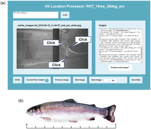
A digital high-speed video camera (Chronos 1.4) was used to record each blade strike through the side viewing window at 1057 to 2111 frames per second (fps). In addition, a GoPro Hero7 video camera was used to film the strike from below at 240 fps. The high-speed videos were analyzed with a bespoke post-processing tool () to determine the relative location of strike along the length of each fish on a scale of 0 to 1, with 0 located at the tip of the snout and 1 located at the tip of the caudal fin (). For each video, the position of the tip of the head and the tip of the tail, as well as the centerline of the blade, were manually selected in the frame in which the fish body began to bend in advance of the oncoming blade. The relative vertical position of the fish to the blade centerline was computed by the post-processing tool as the intersection between a horizontal line at blade center and a line defined by the selected head and tail points on the fish. The average relative strike location was calculated for each set of treatment conditions and used to assess differences in strike location within the defined midsection region among test conditions. Strike location averages for any given set of test conditions that were less than 0.5 indicate that more strikes occurred in the region anterior to the dorsal fin, whereas averages greater than 0.5 indicate more strikes occurred in the region posterior to the dorsal fin.
Figure 4. High-speed video analysis used to determine the exact location of strike along the fish body. (a) Relative length scale from 0 (snout tip) to 1 (caudal fin tip) used to classify location of strike along the body length of each fish. (b) Strike location post-processing tool.
2.5. Survival estimation
Immediate (1-hour) and total (immediate and 48-hour combined) survival rates were calculated for each set of treatments as follows:
(1)
(1)
(2)
(2)
where S1 is immediate survival, ST is total survival, A1 is the number of fish alive within 1 hour of being struck, D48 is the number of fish that died during the 48-hour post-test holding period, and N is the total number of fish tested for a specified test condition (i.e. blade, strike location, and strike velocity). N varied between 25 and 101 across conditions tested, depending on the availability of fish at that stage of testing, and the expected survival rate for the treatment. Adjusted total survival was calculated as
where SC is total control survival. The modified Wald method was used to calculate confidence intervals for the survival estimates (i.e. proportional data with a binomial outcome) (Agresti and Coull Citation1998).
3. Results
In general, strike survival was higher for strikes with average L/t ratio of approximately 1.4, compared to average L/t of 2 (). Slant angle also affected survival for strikes with the RHT blade, with 10 m/s strike survival ranging from 98% at the 30° strike location (Condition g) to 26.8% at the 90° location (Condition u) (). Additionally, the location of strike along the body and resulting interaction between the fish and the blade were found to strongly affect strike survival. For fish with an average L/t of 2 struck at 10 m/s by the EPRI analogue blade, 68% survived when the average strike location was 0.58 (condition b), but only 7.9% survived when the average strike location was 0.36 (Condition c).
About 94% of strike and control mortalities were immediate (within 1 hour of strike) for all test conditions. Also, more than half of all delayed mortalities occurred for the smaller fish size group tested with the RHT blade at the 30° strike position and 7 m/s strike velocity (Condition d). There may have been some type of test-related effect that led to increased delayed mortality for this test group (i.e. the observed delayed mortality was an artifact of the testing and not due to strike).
Rotational orientation about the long axis of the fish could not be controlled and varied among tests. Side strikes were the most common (about 24% to 88% by test condition), followed by ventral strikes (about 6% to 48% by test condition) and dorsal strikes (0% to 26% by test condition). There were no consistent trends in survival related to fish orientation to the blade leading edges when struck.
The majority of external injuries sustained by fish struck by a blade were hemorrhaging and bruising. Very few fish experienced eye damage, fin tears, or lacerations. The majority of strike mortalities suffered internal hemorrhaging, broken spines, and/or gill hemorrhaging. Scale loss of 3%–20% was the most commonly observed for all strike and conditions evaluated and was likely due to test-related handling, due to similar to scale loss rates observed in the control test groups. Less than 3% of the fish across all trials experienced greater than 40% scale loss.
4. Discussion
4.1. Strike location effects
Inspection of the strike location calculated from high-speed video analysis revealed trends in the location of strike among test conditions. The strike location varied from condition to condition due to inconsistencies in the process of manually positioning the fish within the tank; however, this positioning was relatively consistent within a single test condition with standard deviations ranging from 0.04 to 0.08 (). Average strike location was 0.61 (Condition a) and 0.58 (Condition b) for the first two test conditions evaluated with the EPRI blade, respectively, and 0.36 for a third (Condition c), in which strikes were deliberately directed closer to the head. A considerably lower survival rate, 7.8%, was observed for Condition c compared to strikes performed under otherwise identical test conditions (Condition b) in which the average body strike location was 0.58 and survival rate was 68%. The average strike location ranged from 0.32 to 0.56 for the RHT blade.
In general, strikes occurring near the caudal region (i.e. strike location 0.5 and greater) caused the tail to bend and deflect out of the way of the blade and, subsequently, the upper body to “fold over” as the blade passed beneath (). The horizontal position of the fish did not change substantially, indicating a minimal change in velocity and, therefore, a potentially smaller force felt by the fish.
Figure 5. Strike snapshots from high-speed video for the four types of strikes observed, based on relative body strike location (a) 0.5 and greater; (b) 0.44 to 0.5; (c) 0.30 to 0.43; (d) Less than 0.29.
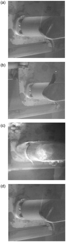
Strike locations closer to the center of mass of the fish (approximately 0.30 to 0.43) caused the fish midsection to be “pinned” to the leading edge of the blade with the head and tail wrapping around in a manner where the body was fully conformed to the leading edge shape (). These fish were carried for a short distance at the blade velocity before sliding over the top of the blade and continuing to move down the length of the tank after the blade had passed. Strikes in this region also appeared to produce a large change in velocity of the fish, from stationary to approximately full blade speed. Consequently, a larger force may have been exerted on fish struck in this region.
Strikes occurring at relative body locations less than 0.30 (i.e. closest to the head), which occurred infrequently, appeared to deflect the head and cause fish to pass under the blade after strike (). These near-head strikes appeared to cause a change in the velocity of the fish that was less than fish struck at body locations between 0.30 to 0.43, but higher than observed for fish struck in the caudal region.
Most of the fish tested with the RHT blade were struck at relative body length locations between 0.44 and 0.50, where neither pinning nor folding effects were observed (). Across all slant angles tested, fish struck in this region typically conformed to the leading edge shape during strike, but experienced relatively small changes in velocity and limited movement down the length of the tank post-strike. These observations suggest that these fish experienced a lesser impact than fish struck in the 0.30 to 0.43 region.
4.2. Slant angle effect
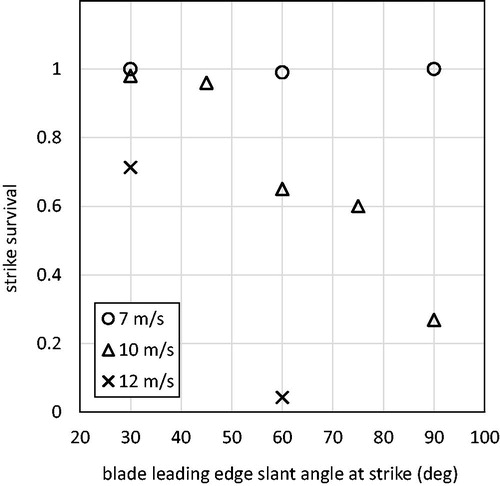
The effect of leading edge slant angle was evaluated by examining the results of tests conducted at multiple angles with each combination of L/t ratio and strike velocity. Strikes at slant angles of 30°, 60°, and 90° were conducted for most combinations of L/t ratio and strike velocity. Additional strikes at 45° and 75° were tested with the RHT analogue blade at 10 m/s and L/t of 2. For these tests, survival declined from 98% at the 30° slant angle position (Condition g) to 26.8% at the 90° slant angle position (Condition u) (). For the two strike angles (30° and 60°) tested with the RHT blade and the larger fish at 12 m/s, there was also a decrease in survival with an increase in slant angle (). For the 7 m/s strikes, survival was at or near 100% for all three slant angles evaluated (30°, 60°, and 90°) with the RHT blade and larger fish ().
Figure 6. Relationship between slant angle and total strike survival for the RHT analogue blade with L/t of 2 at 7 m/s, 10 m/s, and 12 m/s.
All of these tests were conducted with fish oriented perpendicularly to the blade. Fish oriented at other angles to the leading edge may have higher survival rates depending upon where on the body they are struck (EPRI Citation2011; Bevelhimer et al. Citation2019). While these test results revealed no difference in survival due to the rotational orientation of the fish to the blade, previous studies have demonstrated that fish struck laterally typically suffer greater injury and mortality than fish struck dorsally or ventrally (EPRI Citation2008, Citation2011; Bevelhimer et al. Citation2019).
5. Conclusions
The results of strike testing with the blunt leading edge analogue blades used in this study are generally consistent with findings of previous strike tests conducted using the same test apparatus (EPRI Citation2008, Citation2011) and those reported by Turnpenny et al. (Citation1992) and Bevelhimer et al. (Citation2019) with different strike test setups. For all conditions, the smaller L/t ratio resulted in higher survival rates than the larger L/t ratio at similar strike velocities and blade slant angles (i.e. strike location along the length of the leading edge), with the exception of tests with the RHT blade at 7 and 10 m/s at the 30° location, for which survival was 98% or higher for both L/t ratios. While strike survival for the first two tests with the EPRI blade was higher than previous tests conducted with this blade (EPRI Citation2008, Citation2011), post-test analysis of strike location along the body length of each fish revealed a sensitivity of this value to measured survival, which may help to explain the discrepancy.
Study of the high-speed video footage captured across all strike conditions revealed trends in the observed dynamics of strike and measured strike survival. All videos were analyzed to determine the position of the fish relative to the blade centerline at the moment in which the fish began to bend in advance of the strike, and this position was reported on a scale from 0 to 1, where 0 is the tip of the snout and 1 is the tip of the caudal fin. At these low L/t ratios (1.14 to 2) and and strike speeds between 7-12 m/s, anesthetized fish were observed to interact with the oncoming blade in four distinct ways, depending on the relative position of the fish to the blade centerline:
Strikes occurring closer to the tail (strike location 0.5 and above) caused the tail to bend out of the way of the blade, and subsequently the upper body to “fold over” as the blade passed beneath. The horizontal position of the fish did not change substantially, indicating a minimal change in velocity.
Strike locations in the midsection but closer to the head (approximately 0.3 to 0.43) caused the fish midsection to be “pinned” to the leading edge of the blade, with head and tail wrapping around such that the full body of the fish was conformed to the leading edge. These fish were carried some distance at the blade velocity before slipping over the top of the blade, and continuing to move down the tank after the blade had passed. These conditions represented a full change in velocity of the fish from stationary to blade speed, and therefore a larger force felt by the fish.
Strikes occurring at position 0.3 and below were the least common, and tended to deflect the head and cause the fish to pass under the blade after strike. These conditions tended to impart some change in velocity to the fish that was less than the 0.3 to 0.43 condition, but higher than the near-tail strikes.
At relative body length locations between 0.44 and 0.50, neither pinning to the blade nor folding effects were observed. Fish struck in this region typically conformed to the leading edge shape, but experienced relatively small changes in velocity and limited movement down the length of the tank post-strike. These observations indicate that the fish were exposed to a lesser exerted force than fish struck in the 0.3 to 0.43 region.
While strike survival at 7 m/s was 98% or above for both fish size groups across all slant angles tested, survival of fish struck with the RHT blade at 10 m/s and 12 m/s increased significantly with decreasing (i.e. more acute) slant angle. These results indicate that steeply slanted blunt blades may improve strike survival. The 100 mm thick RHT blade strikes resulted in 96% and 98% survival at 45° and 30° slant angle, respectively, when tested with an L/t of 2 at 10 m/s. In past testing, the straight leading edge of the EPRI 100 mm thick blade showed similar survival at 5 m/s with the same L/t ratio (EPRI Citation2008, Citation2011).
The high survival rates achieved at strike speeds of 10 m/s and L/t ratio of 2 with acute slant angles present an opportunity to design blades for high strike survival while enabling economically feasible turbine and generator speeds. It may be valuable to extend this study in several ways, including testing with additional species, quantification of likelihood of strike within the sensitive body region associated with the highest mortality, and further assessment of the sensitivity of mortality to position of strike on the fish body for slanted thick blades. Taken together, this research can help to define safe strike limits for turbines designed to operate at moderate to high speeds while allowing safe passage of fish comparable to or smaller in length to the thickness of the blade leading edge.
Disclosure statement
No potential conflict of interest was reported by the authors.
References
- Agresti A, Coull B. 1998. Approximate is better than “exact” for interval estimation of binomial proportions. Am Stat. 52(2):119–126.
- Amaral S, Coleman B, Rackovan J, Withers K, Mater B. 2018. Survival of fish passing downstream at a small hydropower facility. Mar Freshwater Res. 69(12):1870–1881.
- Basham LR, Delarm MR, Athern JB, Pettit SW. 1982. Fish transportation oversight team annual report, FY 1981: Transport operations on the snake and Columbia rivers. NOAA Technical Memorandum NMFS F/NNR-2. Environmental and Technical Services Division, Northwest Regional Office, National Oceanic and Atmospheric Administration, National Marine Fisheries Service, Portland, OR, USA.
- Bevelhimer M, Pracheil B, Fortner A, Deck K. 2017. An overview of experimental efforts to understand the mechanisms of fish injury and mortality caused by hydropower turbine blade strike. Oak Ridge National Laboratory. Report No: TM-2017/731.
- Bevelhimer M, Pracheil B, Fortner A, Saylor R, Deck K. 2019. Mortality and injury assessment for three species of fish exposed to simulated turbine blade strike. Can J Fish Aquat Sci. 76(12):2350–2363.
- Brown J, Limburg K, Waldman J, Stephenson K, Glenn E, Juanes F, Jordaan A. 2013. Fish and hydropower on the U.S. Atlantic Coast: failed fisheries policies from half-way technologies. Conserv Lett. 6(4):280–286.
- EPRI. 2008. Evaluation of the effects of turbine blade leading edge design on fish survival. Electric Power Research Institute. Report No.: 1014937. Prepared by Alden Research Laboratory Inc, Palo Alto, CA, USA.
- EPRI. 2011. 2010 tests examining survival of fish struck by turbine blades. Electric Power Research Institute. Report No.: 1024684. Prepared by Alden Research Laboratory Inc., Palo Alto, CA, USA.
- Francfort J, Cada G, Dauble D, Hunt R, Jones D, Rinehart B, Sommers G, Costello R. 1994. Environmental mitigation at hydroelectric projects volume ii: benefits and costs of fish passage and protection. Idaho National Engineering Laboratory, Idaho Falls, ID, USA. Report No.: 1218136.
- Franke G, Webb D, Fisher R, Mathur D, Hopping P, March P, Headrick M, Laczo I, Ventikos Y, Sotiropoulis F. 1997. Development of environmentally advanced hydropower turbine system concepts. Idaho Falls, ID: US Department of Energy. Report No.: 2677-0141. Prepared for Voith Hydro.
- Hogan T, Cada G, Amaral S. 2014. The status of environmentally enhanced hydropower turbines. Fisheries. 39(4):164–172.
- Moring J. 2005. Recent trends in anadromous fishes. In: Robert Buchsbaum, Judith Pederson, William E. Robinson, editors. The decline of fisheries resources in New England: evaluating the impact of overfishing, contamination, and habitat degradation. Cambridge (MA): MIT Sea Grant College Program; p. 25–42.
- Neitzel DA, Abernethy CS, Lusty EW, and Prohammer LA. 1985. A fisheries evaluationof the sunnyside canal fish screening facility, Spring 1985: Annual Report. U.S. Department of Energy Contract DE-AC06-76RLO 1830.
- NMFS. 2011. Anadromous salmonid passage facility design. Portland, OR, USA: National Marine Fisheries Service, Northwest Region.
- Turnpenny A. 1998. Mechanisms of fish damage in low-head turbines: an experimental appraisal. In: Jungwirth M, Schmutz S, Weiss S, editors. Fish migration and fish bypasses. Oxford (UK): Fishing News Books, Blackwell Publishing; p. 300–314.
- Turnpenny A, Davis M, Fleming J, Davies J. 1992. Experimental studies relating to the passage of fish and shrimps through tidal power turbines. Prepared for AEA Technology, Harwell National Power PLC.
- Turnpenny AW. 1981. An analysis of mesh sizes required for screening fishes at water intakes. Estuaries. 4(4):363–368.
- USFWS. 2017. Fish passage engineering design criteria. Hadley, MA, USA: US Fish and Wildlife Service, Northeast Region R5.