
Abstract
Complex biological systems often provide ready solutions for contemporary engineering. One such organism might be sponges, primitive, tissueless animals whose evolution over 600 million years has allowed them to become highly specialized. An example of such an organism is the freshwater sponge Spongilla lacustris L., an organism that filters water. This study aimed to investigate the 3D structure of the aforementioned sponge using a broad spectrum of techniques such as Microcomputed Tomography (µCT), Scanning Electron Microscopy (SEM), Confocal Laser Scanning Microscopy (CLSM), and Light Microscopy. Additionally, these techniques have been used to correlate sponge architecture with mechanical properties using the concept of tensegrity, i.e., the feature of architectural structures that self-stabilize by balancing multidirectional, often opposing, tensile and compressive forces. A more detailed look at the structure of the sponge skeleton reveals that it is based on two elements: rigid siliceous spicules, chitin in in fibres with cementing collagen-type spongin material. The coexistence of these elements in the sponge structure determines the mechanical properties and, consequently, the sponge skeleton’s postulated tensegrity. Our observations indicate that the integrity of loose megascleres is realized by sponging material surrounding the bundles of spicules. Our distinction of skeletal elements was determined by the number of spicules in the bundle, the direction of spicule position relative to the main body axis, and the way the elements were connected. The arrangement of the bundles described above has important implications for the mechanical properties of the sponge skeleton and, consequently, for the tensegrity hypothesis.
1. Introduction
Freshwater sponges (Porifera: Demospongiae: Spongillida) are an essential component of the aquatic ecosystem, filtering dissolved organic matter and particles of a smaller size range than other benthic invertebrates. Moreover, sponges are sensitive to environmental stress. A growing interest in freshwater sponges results from, their ability to filter large volumes of water and sensitivity as bioindicators in diagnosing the aquatic environment state (Dröscher & Waringer Citation2007; Evans & Kitting Citation2010; Manconi & Pronzato Citation2000; Masangkay et al. Citation2022).
Over billions of years sponges evolved a particular filtering system, a function of their architecture and dynamic integration of mechanical forces with sponge metabolism, forming a unique niche in changing aquatic environment (Bart et al. Citation2019). From an environmental perspective, the sponge’s body by filtering water increases the retention time of organic substances, allowing them to be metabolized by the sponge cells and by organisms that colonize the sponge. Thus, sponge’s body creating a niche for other living organisms (bacteria, algae, insect larvae).
Sponges filtrate an organic matter from water. The uptake, intracellular digestion, and distribution of nutrients are possible thanks to groups of digestive cells represented by choanocytes and archaeocytes (Godefroy et al. Citation2019). The sponge may be described as a pipe system where the water pressure differences generate the proper flow rates. The aquiferous system (canal system) requires dynamic readjustments, to adapt to environmental changes and maintain the proper pressure difference (Leys et al. Citation2011). This integration potentially operates via a tensegral system. Tensegrity is a feature of architectural structures that self-stabilize by balancing multidirectional, often opposing, tensile and compressive forces. Tensegrity maintains optimal shape and ensures adequate strength and structural integrity despite the stresses involved (Peña et al. Citation2010; Jezierska Citation2007).
The sponge lacks any organized tissues (e.g. muscle tissue) but may carry out a series of peristaltic-like contraction-expansion cycles (Elliott & Leys Citation2007). The movement of water in sponge body is forced by the pumping units (choanocyte chambers and choanocytes with flagella) (Dahihande & Thakur Citation2021).
This study aimed to investigate the 3D structure of a sponge (Spongilla lacustris) and to correlate its body architecture with mechanical properties using the concept of tensegrity.
In the conducted research, we utilized a wide range of techniques such as Computer Microtomography (µCT) and Confocal Laser Scanning Microscopy (CLSM), to visualize internal structures. The technique that works particularly well for imaging living organisms’ internal structures is microtomography (Neues & Epple Citation2008; Zou et al. Citation2011). In the case of a sponge, X-ray is absorbed by the hard elements, such as silica spicules, while organic soft elements are more challenging to analyze, but modern detectors’ sensitivity also solves this problem, allowing for 3D distribution analysis of such elements (Mizutani & Suzuki Citation2012; Karcz et al. Citation2015; Martins et al. Citation2021; Stocchino et al. Citation2021; Manconi et al. Citation2022). However, detailed interpretation of µCT images required additional imaging techniques such as Scanning Electron Microscopy (SEM), Energy-Dispersive X-ray Spectroscopy (EDS), light microscopy combined with chemical staining of the analyzed elements, or in vivo analysis using CLSM. These techniques complement the information that allows completing the analyzed biological structures’ picture (Manconi et al. Citation2008; Woznica et al. Citation2010).
2. Material and methods
2.1. Characteristic of Spongilla lacustris
The freshwater sponge Spongilla lacustris Linnaeus, 1759 is classified into the phylum Porifera, class Demospongiae, order Spongillida, family Spongillidae, based on the nature of the mineral skeleton organic fibrous skeleton and presence of aquiferous system canals. It is one of the most common and widespread freshwater sponges in the northern hemisphere (Manconi & Pronzato Citation2000). They are sessile benthic organisms, with their basal body portion adhering tightly to the base.
The sample with a volume ~10 × 10 cm covering the whole sponge body, was collected in Goczałkowice Dam Reservoir (Southern Poland) from concrete in the harbor, under the water surface. Fully grown organism had numerous branches, ~6 ± 2 mm in diameter and ~60 ± 30 mm in length. Sponge identification was made on the basis of morphology and appearance of megascleres and microscleres (Simm Citation1953; Lopp et al. Citation2007). Megascleres were smooth and straight slightly curved. There were numerous microscleres in the sponge pinacoderm (Supplementary Material 1). They were slightly curved oxeas, entirely covered with small spines. Their mean length was 71 µm (SD = 9 µm, n = 47). The morphology of Spongilla lacustris microscleres from the same site was presented by (Karcz et al. Citation2015).
The used samples were preserved adequately to the applied research techniques. The sponge’s freshly fixed fragments from central digitiform (finger-like) body portions were used in analyses using confocal microscopy and analysis of sponge branch movements. For analyses using X-ray microscopy and SEM, these sponge fragments were frozen in 73 K and lyophilized (Karcz et al. Citation2012, Citation2015).
2.2. SEM EDS microscopy
Scanning electron microscopy of sponge fragments Spongilla lacustris was performed at a low accelerating voltage of the primary beam without any coating or heavy-metal contrasting of the samples, as previously described(Drab Citation2018). The samples were fixed with 2.5% glutaraldehyde in 0.1 M cacodylate buffer for 30 minutes at 4°C, then washed in water and dehydrated in series of methanol solutions (25%, 50%, 75%, 100%, 100%) in one-hour steps at 4°C. Samples underwent critical point drying with methanol exchanged for liquid CO2 in an automatized approach (CPD300 AUTO, Leica Microsystems, Vienna, Austria) and imaged with cross-beam SEM equipped with Schottky field-emission cathode (Auriga 60, Carl Zeiss, Oberkochen, Germany) at 0.8 kV accelerating voltage, thus the imaging was performed within a mode referred to as the low-voltage, field-emission scanning electron microscopy (LV-FESEM) of non-labeled, critical point-dried sample. For energy-dispersive X-ray spectroscopy EDS analysis (Bruker Nano, 6160 X-Flash detector model, Berlin, Germany integrated into Zeiss Auriga −60 SEM) of sponge elemental composition, 8 kV accelerating voltage of primary beam was used instead of 0.8 kV, and the corresponding images were correlated based on topographical features. Two-dimensional maps of elements were generated with the Bruker Esprit 1.9 Quantax 200 software.
2.3. Xray microscopy and µCT tomography
The sponge body was frozen in liquid nitrogen at 73 K and freeze-dried (−50°C, 50 mbar, 48 h) (Karcz et al. Citation2012). The fragment of sponge was mounted in a holder and was scanned with use ZEISS Xradia 520 Versa X-ray Microscope (Carl ZEISS). Sponge was rotated horizontally 360°, scanning energy was 40 kV, for voxel size 5.9834: number of projections 995; for voxel size 2.508: optical magnification 4, 2002 projections; for voxel size 0.95 µm: optical magnification 4; LE 1 filter, number of projections 993; and for voxel size 0.4424: optical magnification 20x, number of projections 963.
2.4. Semi-thin sections and optical light microscopy
The central digitiform branches sponge fragments were cut by a razor into several small cube-like pieces 1 × 1 × 1 mm and fixed in a freshly prepared 2.5% glutaraldehyde in a 0.1 mol phosphate buffer (pH 7.4) for 1 day. The material was then washed several times in a 0.1 mol phosphate buffer (pH 7.4) and postfixed for 2 hr in 1% OsO4 in the same phosphate buffer. The material was next rewashed in phosphate buffer and dehydrated in a graded series of ethanol, replaced with acetone and embedded in an Epoxy Embedding Medium kit (Sigma-Aldrich, St. Louis, MO). Semithin sections (0.8 µm thick) were cut on a Leica Ultracut UCT ultramicrotome (Leica Microsystems, Wetzlar, Germany), stained with 1% methylene blue in 0.5% borax and examined using an Olympus BX60 microscope equipped with an XC50 digital camera (Olympus) and cellSens Standard software (Olympus, ver. 1.8.1).
2.5. CLSM microscopy
Fragment of live body of sponge with dimensions of ~5 × 3 × 3 mm was cut and observed in confocal microscope (AxioObserver ZEISS LSM 880 Germany) with C-Apochromat 40x/1.2 W Korr FCS M27 objective. The autoluminescence image of the sponge; was recorded using Airyscan detector. Excitation wavelength 405 nm, detection wavelength 415 nm.
2.6. Image analysis
The micrographs were processed and analyzed using open-source software ImageJ FIJI (Schindelin et al. Citation2015). Stacking of stacks was accomplished using the 3D Viewer plugin (Schmid et al. Citation2010). OrientationJ software was used to analyze the directions of skeletal spicules and fibres in the sponge pinacoderm (Rezakhaniha et al. Citation2012). Projection onto a surface parallel to the angle surface was used to measure the angles between the skeleton elements. The measurements were made using the Angle Tool extension of ImageJ (Longair et al. Citation2011; Ferreira & Rasband Citation2012). Images of micrographs and reconstructions were composed using CorelDraw Suite 2020.
2.7. Mechanical analysis
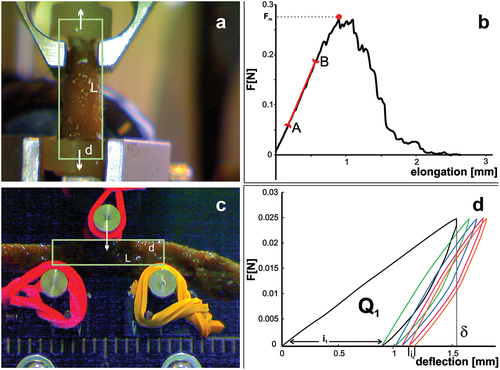
Mechanical properties of the specimens were determined using the MTS Synergie 100 universal testing machine with a 10 N load cell in tensile and 3-point bending testing, at a speed of 10 mm/min. The samples were central digitiform branches parts of different sizes from the same individual. These samples were assumed to be cylindrical in shape and their sizes, diameter (d) and length (L), were measured from photographs in ImageJ software. For the tensile test, L was the distance between the attachment points of the sample ()), and for 3-point bending, the distance between the support points ()).
Figure 1. Measurement of sponge body mechanical properties using the MTS Synergie 100 universal testing machine. (a) Montage of sponge in the tensile test. (b) Elongation-force curve: AB The rectilinear section of the curve; red point: maximum force value. (c) Montage of sponge in the 3-point bending test. (d) Force-deflection curve for five loading-unloading cycles, Q1 – energy dissipated within the first cycle; δ – deflection in the first cycle.
The tensile (ET) and bending (EB) moduli of sponge body elasticity were determined using mechanical tests ().
In tensile tests modulus ET was determined from the stress–strain curve specifically the slope of the linear region. From the maximum force Fm measured in the tensile test, the strength of the sample was determined, maximum stress before failure, σm = Fm/A, where A is cross section of the sample.
In bending tests, samples were cyclically loaded with a force of Fm = 0.025 N and unloaded, then rotated around the axis by 180° and the test was repeated. Modulus EB was determined from the formula EB = (Fm × L^3)/(48 × δ × I), where δ is deflection of the specimen at the first cycle.
The energy required to deform the specimen Q was determined as the area under the curve F = F(deflection) using the standard trapz function (Matlab R2020b).
In both, tensile and 3-point tests modulus was determined from the stress–strain curve specifically the slope of the linear region. From the maximum value of the force Fm measured in the tensile test, the strength of the specimens m = Fm/A was determined, where A is cross-section area of the specimen.
Each test was performed in 6 replicas, the range of results obtained, arithmetic mean and SD are reported in the results.
A fibrous composite material model is used to describe the mechanical properties of sponges, which describes well the dependence of the modulus of elasticity on the fraction of spicules.
In the cyclic loading test, the energy lost in each cycle decreases, the sample becomes more elastic, hardening occurs (KOEHL Citation1982).
3. Results
3.1. Megascleres of Spongilla lacustris
A general view of the sponge Spongilla lacustris in situ on ). shows the way the sponge is attached to the substrate via a stiffening point while the reconstruction of its selected fragments is visualized utilizing the µCT at different resolutions ().
Figure 2. Image of Spongilla lacustris in its natural environment and reconstruction of a sponge base allowing it to be firmly attached to a substrate. (a) Image of sponge on the surface of concrete. (b) Projection of the 3D reconstruction of the sponge body; optical scan. (c) Developed surface of the sponge base adhering to the concrete surface.
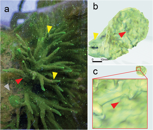
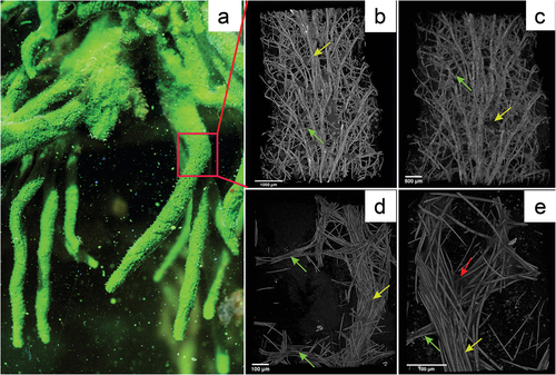
Figure 3. Reconstruction of Spongilla lacustris fragment based on the µCT images. (a) In situ image of the sponge colony and the fragment used for analysis (red frame). (b–e) Computer image reconstructions of the sponge skeleton based on the µCT (X radia Zeiss): (b) skeleton reconstruction in resolution 5.9834 µm/pixel; (c) skeleton reconstruction in resolution 2.508 µm/pixel; (d) skeleton reconstruction in resolution 0.95; (e) skeleton resolution 0.4424.
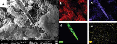
A single megasclere (large oxea) of Spongilla lacustris is a spindle-shaped structure with pointed ends ()). Using EDS method, the dominant presence of Si and O with was demonstrated as major constituents (). Silicon was observed only inside the megasclere and cooccurred there with oxygen, which indicates silica-based structure of this spicule (SiO2) (). Carbon (C) and sulfur (S) were uniformly distributed in the mesohyl confirming amino acids as its main constituents. In megascleres ()) a uniform distribution of silicon was observed along the spicules. The sponge mesohyl was characterized by a lack of silica and presence of high carbon content ()) with co-occurring oxygen and sulfur (). However, not analysed in this regard, miroscleres were present in pinacoderm.
Figure 4. SEM EDS mapping of elements in megasclere and mesohyl of Spongilla lacustris body. (a) General view of the sponge body, topography, SE2 Everhart-Thornley detector, field of view 71 micrometers. (b–e) Corresponding chemical elements’ distribution 2D map of the analyzed object, energy-dispersive X-ray spectroscopy EDS: (b) carbon; (c) oxygen; (d) silicon; (e) sulfur.
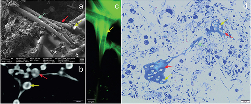
The bundles of spicules and channels of sponge are shown in . The spicules were colorless and transparent as revealed under optical and confocal microscopy, where imaging was possible due to autofluorescence of the membranes covering the spicules (). The diameter of a single spicule was on average 5.18 ± 0.349 µm with a centrally located axial canal of 0.49 ± 0.079 µm diameter. The silica spicules strongly absorbed X-rays in comparison to the rest of the sponge body, while the area of the central spicule was characterized by reduced X-ray absorption. The channel lumen was characterized by increased luminescence ()) and intense blue coloration when stained with methylene blue ()) indicating the presence of proteins inside the spicule. The axial canal of the megasclere can be observed in X-ray microscopy images in the form of central areas of lower density in the cross-sectional area of the spicule ()), and at the breakpoints of the spicule in the SEM images ()).
Figure 5. Image of Spongilla lacustris megascleres with a visible channel in the centrum in different imaging techniques. (a) SEM image, view of the sponge spicules, topography, SE2 Everhart-Thornley detector, field of view 112 micrometers, low-voltage imaging mode. (b) X-ray microscopy (c) CLSM confocal microscopy. (d) Light microscopy and histochemical methods (methylene blue staining).
3.2. Structure of the sponge branch
We propose that the integral structures of S. lacustris utilize the extrinsic movements of water to support medium exchange. We indicate major four structures that integrated the medium and water exchange, (I) made of siliceous megascleres, the flexible, inextensible branch (primary ascending fibres) in its uninterrupted continuity from the base plate to the apical part of sponge body; (II) rigid transverse beams – crossbars (secondary fibres/tracts) creating semi-flexible connections between the branches of the sponge skeletal network; (III) sponge pinacoderm stiffed by elements of the skeleton, and (IV) internal aquiferous canals channels in the sponge body.
The branch forms an acute angle of 28.3° ± 7.79° with the lateral branch ( yellow arrow). The frequency of branching was ~2.6 branches per 1 mm of main branch length on the observed sponge fragment, and the distance between successive branches averaged 354.5 ± 17.30 µm. The sponge branch consisted of bundles of parallel megascleres, the number of which varied and averaged around 12.3 ± 7.73 megascleres within the bundle cross-section. An analysis of the arrangement of megascleres in a bundle is shown in . The bundle was dominated by spicules arranged parallel to each other ( red arrow) and accounted for 35.56%; lateral branches of the bundle were arranged at angles of 45 to 75 relative to the bundle and accounted for 32.72% ( yellow arrow); auxiliary skeletal reinforcements (angles of 105° to 120°), accounted for 23.19% of the bundles ( blue arrows).
Figure 6. Reconstruction the spicule bundle of Spongilla lacustris skeleton with marked directions of individual megasclere based on µCT. (a) Branch with branchings. (b) Branch with color-marked angles of the megascleres according to the color scale (angle determined in relation to horizontal line). (c) Distribution of the angles between spicules.
The beam reconstructions allowed to determine the density of the branch branching and the density of the auxiliary beams ()). The obtained images demonstrated that the auxiliary beams propagate radially ()). The reconstructions of the branch showed that the megascleres were evenly distributed in the bundle and their arrangement was uniform across the whole analyzed field at density of 39.7 ± 1.55/mm2 (). The distances between nearest neighboring bundles of spicules in cross-section averaged 137.2 ± 54.01 μm (). Branches of the sponge skeleton directed toward the surface of the sponge body and formed protruding spikes on the surface of the sponge body, which formed a protective mechanism but were also an important structural element forming a support for the pinacoderm surrounding the sponge body ()). The results of the measurements are summarized in .
Figure 7. Reconstruction of individual beam and its branches based on µCT (X radia Zeiss) and places where megascleres emerge from the pinacoderm of Spongilla lacustris. (a) Visualization using Neurite Tracer and OrientationJ at various angles, red arrow – one of the central branches selected for analysis, green arrow – transverse crossbars beams. (b) Projection on the ground plane (red arrow – central beam; green arrows – transverse crossbars beams). (c–e) Places where megascleres emerge from the pinacoderm (blue triangles) and the location of the sponge skeleton branch (yellow circles).
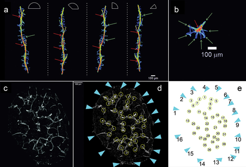
Table I. Measurement values of Spongilla lacustris skeletal elements obtained by analyzing images from X ray μCT.
3.3. Crossbars
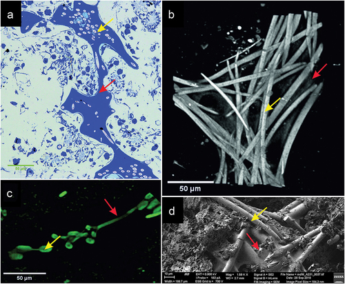
Between the close lying branches of the skeleton there were transverse bundles made up of 2–8 spicules connecting to the branch at an angle of 93.0° ± 10.21°. The ends of the spicules of the transverse bundles were inserted between the spicules ()), which formed a kind of hinge allowing in-plane movements and restricting lateral movements. 3D reconstruction of the branch structure showed that along the length of 1 cm there were ~50 such transverse crossbar bundles ()), and their average length was 373.5 ± 82.11 µm. When the branches ran close to each other, the crossbars formed connections between them which visually created a ladder-like structure. A top projection on the XY plane showed that the crosspieces propagated radially from the branch (). The stabilization of the skeleton was possible due to the structure (spongin) present around the bundles, which stained blue with methylene blue ()), and the thin membrane between the spicules visible in the X-ray microscopy and SEM image reconstructions () visible due to its green autofluorescence ()).
Figure 8. Image of the intersection of spicule bundles in the siliceous-organic skeleton of Spongilla lacustris. (a) Methylene blue stained cross-section. (b) Reconstruction of the µCT image (0.95 µm) of beams and crossbars junction. (c) Image of the two beams and crossbars in confocal microscopy image. (d) SEM image.
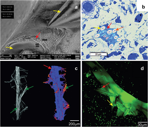
Analyses utilizing the aforementioned techniques revealed the presence of fibrous elements (spicule) on the surface of the skeleton branch (), where SEM analyses showed them to be multilayered. The thickness of a single spongin layer visible in the SEM images was 62.3 nm, and the total thickness of the spongin multilayer (~6 layers) was 344.0 nm ()). The multilayer nature of the spongin structures was also confirmed by the membranes around the branches captured by optical microscopy techniques stained with methylene blue ()). Analyses using CLSM indicated that the fibrous elements covering the skeleton branch exhibited strong autofluorescence ()). The utilized imaging techniques have allowed spatial localization of spongin, which closely surrounded the silica elements in the form of filaments and membranes ().
Figure 9. Cross-sections of the sponge and surface of Spongilla lacustris. (a–h) Cross-sections of the sponge 50 stack thick (~250 µm) with centrally arranged bundles of the main branch (dark nodes) and lateral branches, and spikes extending above the surface of the sponge. (i) Surface of sponge body with spikes constituting the ends of the side arms of the skeleton (SEM). (j) Surface of sponge body (in situ photography).
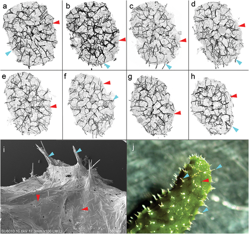
Figure 10. Imaging of the sponge Spongilla lacustris skeleton, based on SEM (Hitachi Uhr FE-SEM Su 8010); optical microscopy with methylene blue dying; µCT computed Tomography (X radia Zeiss) and CLSM technic. (a) The megascleres with the multilayer membrane on the surface. (b) Cross-sections of sponge body with megascleres and multilayer coating. (c) Reconstruction of sponge skeleton’s branch and lateral branching with marked enclosed layer. (d) Megascleres and autofluorescent layer. Megascleres central beam with marked beam forks and multilayer membrane.
3.4. Pinacoderm
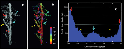
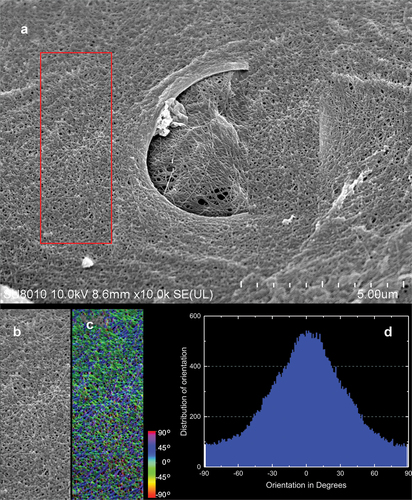
The external part of the sponge’s body is a pinacoderm that is stiffened by a dense network of spicula bundles extending above the sponge surface (). These supports were evenly distributed over the entire surface of the sponge’s body creating tipi-like structure ()). SEM images show fibrous structures with fibres arranged at −45°to 45° from the sponge axis. On the analyzed surface of the pinacoderm there were numerous circular pores of the diameter between 1.3 and 44.6 µm (median 3.32 µm) ()). SEM analysis showed that pinacoderm is a dense web of spongin fibres with dominating 0° to 30° directions of fibres ().
Figure 11. SEM image of protocolagen fiber in pinacoderm of the sponge Spongilla lacustris. (a) Pinacoderm surface with pores (red box indicates analyzed surface, SEM image by Jagna Karcz). (b) Fragment of pinacoderm utilized to analysis. (c) Analysis of fiber direction in the pinacoderm (calculated angles visualized according to color scale). (d) Distribution of fiber orientation in the pinacoderm.
3.5. Mechanical aspect
The sponge body retain their shape and vertical orientation not only in water but also after being removed from it. After removal, the distal parts of the sponge limp slightly. Elongation–force curve with maximum force value is shown in ). The results of cyclic loading tests showed that in each cycle the energy loss decreased, the elasticity of the analyzed sample increased, and the sample hardened ()). The value of the elastic modulus ET varied from 0.33 to 0.83 MPa, with an average value of 0.59 MPa (SD = 0.18 MPa). The strength of the tested samples varied from 0.0019 to 0.0035 MPa, the average value is 0.0027 MPa (SD 0.0008 MPa). The tensile bending modulus EB was determined for five samples, and its value varied from 0.0012 to 0.0043 MPa, where the average value was 0.0022 MPa (SD 0.0012 MPa).
4. Discussion
As one of the oldest multicellular organisms on Earth (appeared over 600 million years ago), sponges (Porifera) are characterized by high variability in anatomical structure between species (Yina et al. Citation2015) or in morphology between individuals of the same species. These diverse anatomical or morphological solutions represent adaptations to the specific habitats. The limitations of sponges’ ability to function, such as lack of active movement, require them to have a different life strategy. The habitats evolutionary conservative in physicochemical aspects pressed the sponge to adapt to these conditions via novel anatomical features that have been consolidated over millions of years of evolution since they are lasting almost unchanged to the present day.
A set of preserved anatomical features of sponges have been identified in this study as potential components of the tensegrity system, that we postulated based on our findings. Therefore, in addition to the anatomical features that allow the sponge to exchange the medium, a specific habitat appeared necessary, which would actively force the movement of the sponge’s body thus, allowing dynamic changes in the volume of the sponge and, consequently, effective support water exchange in its body. Therefore, exposition to the extrinsic cyclic movement/waves of water is an integral part of the sponge survival strategy.
The variety of skeletal structures found in sea and freshwater sponges results from the adaptation of these organisms to a plethora of specific environmental conditions. The skeleton’s chemical (siliceous, calcareous) and mechanical properties have been developed over hundreds of millions of years (Yina et al. Citation2015). The resulting tensegrity and integrity are important and widespread features of living organisms by which structure can be maintained under varying environmental conditions while optimizing energy consumption (Scarr Citation2020). An important feature of tensegrity structures is their self-organization and ability to stabilize within the system; an increase in tensile stress in one part of the system is offset by an increase in compressive stress in other parts of the system (Jezierska Citation2007). We postulate that the tensegrity of the S. lacustris skeleton is a consequence of its anatomical structure. However, it is challenging to describe which anatomical elements of S. lacustris determine the tensegrity of the sponge body (Supplementary Material 2).
A more detailed look at the structure of the sponge skeleton reveals that it is based on two elements: rigid spicules and elastic spongin containing a type of collagen (). The share of these elements in the sponge structure determines the mechanical properties and, consequently, the sponge skeleton’s postulated tensegrity.
Our observations indicate that the integrity of megascleres is realized by multi-layered membranes surrounding the bundles of spicules (). Our distinction of skeletal elements was determined by the number of spicules in the bundle, the direction of spicule position relative to the main body axis, and the way the elements were connected. The highest number of spicules was observed in the branches (up to several tens of spicules). The main bundles were continuous from the base to the upper part of the sponge. Transverse bundles were cross-sectioned with up to a dozen spicules; auxiliary bundles consisted of a number of spicules. Branches of the main bundles diverged at an angle of ±30 degrees relative to the main bundle () and emerged on the surface of the sponge body above the pinacoderm. Transverse bundles diverged from the main bundles at approximately right angles ().
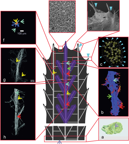
Figure 12. Diagram of the Spongilla lacustris structure. (a) Surface of the sponge’s base adhering to the concrete substratum. (b) Reconstruction of sponge spicular skeleton’s bundle and branch with marked layer. (c, d) Places where megascleres emerge from the pinacoderm. (e) Surface of the pinacoderm (body surface). (f) One of the central branches selected for analysis, projected onto the ground plane. (g, h) Main branch with the branching region.
The arrangement of the bundles described above has important implications for the mechanical properties of the sponge skeleton and, consequently, for the tensegrity hypothesis. Namely, the ends of the crosspieces penetrate the spicules of the main bundles to form a kind of hinge. The way in which the crossbars are connected to the main bundle, involving the penetration of the ends of the crossbars between the spicules of two adjacent main bundles, allows vertical movements while limiting the range of movements in the horizontal plane. The observed radial arrangement of the crossbars around each of the beams stiffen the skeleton structure, giving it elasticity, thus fulfilling one of the conditions of tensegrity. An important element causing the integrity of the overall skeleton is the aforementioned continuity of the bundles from the base to the upper part of the sponge. The large adhesive surface of the base stabilizes the sponge on the substrate and provides rigidity to the skeleton’s base.
Also contributing to the postulated tensegrity of the sponge body are the properties of the pinacoderm covering the body, stiffened (tipi-like) over bundles of spicules ()). The pinacoderm is composed of fibres arranged to provide directed flexibility. This property results from the predominant directions of the fibres (). The occurrence of the membrane surrounding the spicule bundles determines the integrity of its skeleton. The resulting images of membrane were similar to collagen in marine sponges reported in the literature (Exposito et al. Citation2002; Müller et al. Citation2009; Lin et al. Citation2011) and chitin in S. lacustris (Ehrlich et al. Citation2013). The anatomical elements that make up the postulated tensegrity of the body (skeleton including the covering pinacoderm) of the sponge are shown together in .
The extent of elastic deformation is difficult to assess because the connected cells and the chambers distributed within it, have viscoelastic material properties.
Measurement of sample density show that after the fifth cycle, the sample loses a significant amount of water – extrusion by crushing of the chambers is probably the primary energy dissipation process. The shape (volume) of the sample is restored in two ways: through capillary effects and through elastic energy stored in the spongin.
The results of cyclic loading tests (in each cycle the energy loss decreased, the elasticity of the analyzed sample increased, and the sample hardened) are similar to (KOEHL Citation1982). The mechanical effects: energy dissipation, sample hardening, ET dependence on spongin fraction, can be explained by the presence of spongin. The tensile modulus of elasticity ET is close to the values measured for e.g., Sycon ciliatum, Halichondria panicea, sponges whose spicule fraction is less than 0.1 (dry weight of sponge 10%) (KOEHL Citation1982).
Spongin not only provides the integrity of the skeletal elements, also extends the elastic deformation range, increases the strength, resistance to permanent deformation compared to fiber composite.
The vertical bundles, forming the branches, made up of spicule bonded by spongin, located near the axis, allow for flexible, non-destructive, deformation under shear forces (). These bundles divide the sample into layers that reduces the EB value and, consequently, the structure’s stiffness, but increases its strength and resistance to bending caused by drag force (). This way of increasing the elasticity for tension and compression of a vertical beam is characteristic for tensegrity structures.
Figure 13. Graphical representation of the effect of drag force on a sponge skeleton. (a) Force diagram with the image of sponge skeleton reconstructed using µCT image. (b) Interactions occurring in the sponge skeleton as a result of drag force.
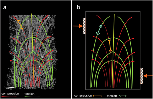
The same can be achieved by increasing the fraction of metabolically “expensive” spicules; however, “cheap” collagen fibres arranged properly (tensegrally) are more optimal, as seen, for example, in vertical fibres connected by spongin in the bundles ()).
The consequence of this structure is also the possibility or support of water exchange in the body of a sponge caused by changes in the volume of its body under the influence of water tides, level fluctuation, and water movement caused by other factors. Such anatomical adaptations can be an inspiration for creating new technologies based on solutions found in nature. An example of their use may be the natural collagen-silica composites in sponges, which inspired the development of analogous synthetic hybrid materials (Ehrlich et al. Citation2018).
Supplemental Material
Download Microsoft Video (AVI) (17.1 MB)Supplemental Material
Download TIFF Image (1.2 MB)Disclosure statement
No potential conflict of interest was reported by the author(s).
Supplementary material
Supplemental data for this article can be accessed online at https://doi.org/10.1080/24750263.2022.2105964.
References
- Bart MC, de Vet SJ, de Bakker DM, Alexander BE, van Oevelen D, van Loon EE, van Loon JJWA, de Goeij JM. 2019. Spiculous skeleton formation in the freshwater sponge Ephydatia fluviatilis under hypergravity conditions. PeerJ 6:e6055. DOI: 10.7717/peerj.6055.
- Dahihande AS, Thakur NL. 2021. Differences in the structural components influence the pumping capacity of marine sponges. Frontiers in Marine Science 8. DOI: 10.3389/fmars.2021.671362.
- Drab M. 2018. Phage aggregation–dispersion by ions: Striving beyond antibacterial therapy. Trends in Biotechnology 36:875–881. DOI: 10.1016/j.tibtech.2018.03.002.
- Dröscher I, Waringer J. 2007. Abundance and microhabitats of freshwater sponges (Spongillidae) in a Danubean floodplain in Austria. Freshwater Biology 52:998–1008. DOI: 10.1111/j.1365-2427.2007.01747.x.
- Ehrlich H, Kaluzhnaya OV, Brunner E, Tsurkan MV, Ereskovsky A, Ilan M, Tabachnick KR, Bazhenov VV, Paasch S, Kammer M, Born R, Stelling A, Galli R, Belikov S, Petrova OV, Sivkov VV, Vyalikh D, Hunoldt S, Wörheide G. 2013. Identification and first insights into the structure and biosynthesis of chitin from the freshwater sponge Spongilla lacustris. Journal of Structural Biology 183:474–483. DOI: 10.1016/j.jsb.2013.06.015.
- Ehrlich H, Wysokowski M, Zółtowska-Aksamitowska S, Petrenko I, Jesionowski T. 2018. Collagens of poriferan origin. Marine Drugs 16:79. DOI: 10.3390/md16030079.
- Elliott GRD, Leys SP. 2007. Coordinated contractions effectively expel water from the aquiferous system of a freshwater sponge. Journal of Experimental Biology 210:3736–3748. DOI: 10.1242/jeb.003392.
- Evans K, Kitting C. 2010. Documentation and identification of the one known freshwater sponge discovered in the California Delta. The Open Marine Biology Journal 4:82–86. DOI: 10.2174/1874450801004010082.
- Exposito JY, Cluzel C, Garrone R, Lethias C. 2002. Evolution of collagens. The Anatomical Record 268:302–316. DOI: 10.1002/ar.10162.
- Ferreira T, Rasband W. 2012. ImageJ user guide user guide imageJ. Image J user guid. 1.46r. DOI: 10.1038/nmeth.2019.
- Godefroy N, Le Goff E, Martinand-Mari C, Belkhir K, Vacelet J, Baghdiguian S. 2019. Sponge digestive system diversity and evolution: Filter feeding to carnivory. Cell and Tissue Research 377:341–351. DOI: 10.1007/s00441-019-03032-8.
- Jezierska E. 2007. Structural tensegrity in materials science. Inżynieria Materiałowa 7:401–406.
- Karcz J, Bernas T, Nowak A, Talik E, Woznica A. 2012. Application of lyophilization to prepare the nitrifying bacterial biofilm for imaging with scanning electron microscopy. Scanning 34:26–36. DOI: 10.1002/sca.20275.
- Karcz J, Woznica A, Binkowski M, Klonowska- M. 2015. SEM-EDS and X-ray micro computed tomography studies of skeletal surface pattern and body structure in the freshwater sponge Spongilla lacustris collected from Goczalkowice reservoir habit (Southern Poland). Folia Histochemica et Cytobiologica 53:88–95. DOI: 10.5603/FHC.a2015.0002.
- KOEHL MAR. 1982. Mechanical design of spicule-reinforced connective tissue: Stiffness. Journal of Experimental Biology 98:239–267. DOI: 10.1242/jeb.98.1.239.
- Leys SP, Yahel G, Reidenbach MA, Tunnicliffe V, Shavit U, Reiswig HM. 2011. The sponge pump: The role of current induced flow in the design of the sponge body plan. PLoS One 6. DOI: 10.1371/journal.pone.0027787.
- Lin Z, Solomon KL, Zhang X, Pavlos NJ, Abel T, Willers C, Dai K, Xu J, Zheng Q, Zheng M. 2011. In vitro evaluation of natural marine sponge collagen as a scaffold for bone tissue engineering. International Journal of Biological Sciences 7:968–977. DOI: 10.7150/ijbs.7.968.
- Longair MH, Baker DA, Armstrong JD. 2011. Simple neurite tracer: Open source software for reconstruction, visualization and analysis of neuronal processes. Bioinformatics 27:2453–2454. DOI: 10.1093/bioinformatics/btr390.
- Lopp A, Reintamm T, Vallmann K, Päri M, Mikli V, Richelle-Maurer E, Kelve M. 2007. Molecular identification, characterization and distribution of freshwater sponges (Porifera: Spongillidae) in Estonia. Fundamental and Applied Limnology 168:93–103. DOI: 10.1127/1863-9135/2007/0168-0093.
- Manconi R, Pronzato R. 2000. Rediscovery of the type material of Spongilla lacustris (L., 1759) in the Linnean herbarium. Italian Journal of Zoology 67:89–92. DOI: 10.1080/11250000009356300.
- Manconi R, Murgia S, Pronzato R. 2008. Sponges from African inland waters: The genus Eunapius (Haplosclerida, Spongillina, Spongillidae). Fundamental and Applied Limnology 170:333–350. DOI: 10.1127/1863-9135/2008/0170-0333.
- Manconi R, Cubeddu T, Pronzato R, Sanna MA, Nieddu G, Gaino E, Stocchino GA. 2022. Collagenic architecture and morphotraits in a marine basal metazoan as a model for bioinspired applied research. Journal of Morphology 283:585–604. DOI: 10.1002/jmor.21460.
- Martins E, Rapp HT, Xavier JR, Diogo GS, Reis RL, Silva TH. 2021. Macro and microstructural characteristics of North Atlantic deep-sea sponges as bioinspired models for tissue engineering scaffolding. Frontiers in Marine Science 7. DOI: 10.3389/fmars.2020.613647.
- Masangkay FR, Manconi R, Milanez GD, Kotepui M, Somsak V, Tangpong J, Karanis P. 2022. Sponges (Porifera: Spongillida) as ecological indicators for parasitic protozoans Cryptosporidium and Giardia infective stages in freshwater ecosystems. Ecological Indicators 139. DOI: 10.1016/j.ecolind.2022.108895.
- Mizutani R, Suzuki Y. 2012. X-ray microtomography in biology. Micron 43:104–115. DOI: 10.1016/j.micron.2011.10.002.
- Müller WEG, Kasueske M, Wang X, Schröder HC, Wang Y, Pisignano D, Wiens M. 2009. Luciferase a light source for the silica-based optical waveguides (spicules) in the demosponge Suberites domuncula. Cellular and Molecular Life Sciences 66:537–542. DOI: 10.1007/s00018-008-8492-5.
- Neues F, Epple M. 2008. X-ray microcomputer tomography for the study of biomineralized endo- and exoskeletons of animals. Chemical Reviews 108:4734–4741. DOI: 10.1021/cr078250m.
- Peña DM, Llorensa I, Sastre R. 2010. Application of the tensegrity principles on tensile textile constructions. International Journal of Space Structures 25:57–68. DOI:10.1260/0266-3511.25.1.57.
- Rezakhaniha R, Agianniotis A, Schrauwen JTC, Griffa A, Sage D, Bouten CVC, Van De Vosse FN, Unser M, Stergiopulos N. 2012. Experimental investigation of collagen waviness and orientation in the arterial adventitia using confocal laser scanning microscopy. Biomechanics and Modeling in Mechanobiology 11:461–473. DOI: 10.1007/s10237-011-0325-z.
- Scarr G. 2020. Biotensegrity: What is the big deal? Journal of Bodywork and Movement Therapies 24:134–137. DOI: 10.1016/j.jbmt.2019.09.006.
- Schindelin J, Rueden CT, Hiner MC, Eliceiri KW. 2015. The ImageJ ecosystem: An open platform for biomedical image analysis. Molecular Reproduction and Development 82:518–529. DOI: 10.1002/mrd.22489.
- Schmid B, Schindelin J, Cardona A, Longair M, Heisenberg M. 2010. Open Access SOFTWARE A high-level 3D visualization API for Java and ImageJ. BMC Bioinformatics 11:274. DOI: 10.1186/1471-2105-11-274.
- Simm K. 1953. Freshwater fauna of Poland. Sponge (Porifera). Warszawa: PWN.
- Stocchino GA, Cubeddu T, Pronzato R, Sanna MA, Manconi R. 2021. Sponges architecture by colour: New insights into the fibres morphogenesis, skeletal spatial layout and morpho-anatomical traits of a marine horny sponge species (Porifera). The European Zoological Journal 88:237–253. DOI: 10.1080/24750263.2020.1862316.
- Woznica A, Karcz J, Nowak A, Gmur A, Bernas T. 2010. Spatial architecture of nitrifying bacteria biofilm immobilized on polyurethane foam in an automatic biodetector for water toxicity. Microscopy and Microanalysis 16:550–560. DOI: 10.1017/S1431927610093815.
- Yina Z, Zhu M, Davidson EH, Bottjer DJ, Zhao F, Tafforeau P. 2015. Sponge grade body fossil with cellular resolution dating 60 Myr before the Cambrian. Proceedings of the National Academy of Sciences of the United States of America 112:E1453–E1460. DOI: 10.1073/pnas.1414577112.
- Zou W, Hunter N, Swain MV. 2011. Application of polychromatic μcT for mineral density determination. Journal of Dental Research 90:18–30. DOI: 10.1177/0022034510378429.