
ABSTRACT
The AlxCoCrCuFeNi (x = 0, 0.8) high entropy alloys (HEAs) were prepared by laser powder bed fusion (LPBF), and the effects of volumetric energy density (VED) and heat treatment on microstructures and mechanical properties of HEAs were investigated. The results show that the CoCrCuFeNi HEA has a single FCC phase structure and exhibits good ductility. Its yield strength is relatively low, being 520 MPa. After the alloy composition was adjusted from CoCrCuFeNi to Al0.8CoCrCuFeNi, the HEA changed from FCC single-phase to FCC + BCC dual-phase structure and the hardness and compressive properties were significantly improved. Among them, the Al0.8CoCrCuFeNi HEA prepared with the VED of 167 J/mm3 has the best mechanical properties, with a compressive yield strength of 652 MPa and good plasticity. After annealing at 600°C and 900°C for 1 h, the mechanical properties of HEAs are significantly improved. In particular, the microhardness and compressive yield strength of the Al0.8CoCrCuFeNi HEA annealed at 600°C for 1 h are 378 HV and 810 MPa, respectively. The coordinated deformation between FCC and BCC domains, back stress strengthening, solid solution strengthening and precipitation strengthening after heat treatment make the Al0.8CoCrCuFeNi HEA achieve a balance of high strength and good ductility.
Introduction
High entropy alloys (HEAs), also known as multi-principal element alloys, which were discovered in 2004 [Citation1,Citation2], usually consist of at least five near-equal atomic ratios of elements, and their excellent physical and mechanical properties have attracted great interest from scholars [Citation3]. In recent years, due to the high entropy effect, the lattice distortion effect, the sluggish diffusion effect and the cocktail effect [Citation4], HEAs have shown unique properties, such as excellent corrosion resistance [Citation5,Citation6], good ductility [Citation7], excellent wear resistance [Citation8], superior high temperature performance [Citation4] and high tensile strength [Citation9,Citation10].
Generally speaking, single-phase high entropy alloys show either higher strength or higher ductility, and it is difficult to achieve a balance between strength and ductility. FCC single-phase HEAs usually have excellent ductility, but the strength of these alloys is usually not high [Citation11,Citation12]. The yield strength of CoCrFeMnNi HEA prepared by laser powder bed fusion (LPBF) is 520 MPa [Citation13,Citation14], and the yield strength of Al0.5FeCoCrNi HEA is 579 MPa [Citation15]. Some researchers have also prepared BCC single-phase HEAs with high strength by LPBF, such as equiatomic ratio AlCoCuFeNi [Citation16] and AlCoCrFeNi [Citation17] HEAs. However, the BCC single-phase HEAs prepared by LPBF have higher strength but lower ductility. Based on this consideration, the design concept of dual-phase (FCC + BCC) HEAs that can increase strength and ductility at the same time was proposed. Studies have shown that the dual-phase HEAs have excellent strength and ductility matching, which is attributed to the cooperative plastic deformation between FCC and BCC phases [Citation18,Citation19]. In 2014, Lu et al. [Citation20] prepared AlCoCrFeNi2.1 dual-phase HEA by arc melting method, achieving a good balance between strength and ductility. Tensile test results show that the fracture stress of as-cast AlCoCrFeNi2.1 is 1186 MPa and the elongation is 22.8%. Meanwhile, the HEAs can still maintain high strength and ductility at 600°C and 700°C.
Generally, HEAs are prepared by traditional casting methods, such as vacuum arc melting and directional solidification casting [Citation21]. Asoushe et al. [Citation22] studied the microstructural evolution of as-cast AlCoCrFeNi2.1 that was thermally machined in the temperature range of 25–500°C, achieving significant strength and ductility at room temperature. Karimi et al. [Citation23] prepared AlCoCrFeNi HEA by LPBF method. The results showed that with the increase of Ni content, the alloy microstructure changed from BCC phase to FCC phase, which had certain effects on the compressive properties, microhardness, strength and ductility. HEAs prepared by traditional methods are costly and have great limitations for producing parts with complex geometry [Citation24,Citation25]. Severe compositional segregation and coarse dendrite grains in casting HEAs result in serious deterioration of mechanical properties.
In contrast, LPBF is an efficient and economical laser additive manufacturing technique that enables the rapid fabrication of metal parts with complex shapes and high dimensional accuracy [Citation26,Citation27] by layer-by-layer laying powder and continuous deposition, which can produce strong and complex structures [Citation28]. Recent studies have shown that HEAs made by LPBF exhibit the characteristics of ultra-fine grains due to the rapid cooling rate (105–107 K/s), giving them greater advantages over casting. Yevgeni et al. [Citation29] prepared FCC single-phase crack-free FeCoCrNi HEAs by combining LPBF and annealing, and their tensile strength and ductility are comparable to those of corresponding HEAs fabricated by ingot metallurgy (IM). Zhu et al. [Citation30] utilized optimized LPBF process parameters to prepare FCC single-phase CoCrFeNiMn HEAs with yield strength of 510 MPa and elongation to fracture of 34%, which are superior to the alloys of the same system prepared by IM. Luo et al. [Citation31] designed and manufactured FCC + BCC dual-phase AlCrCuFeNix (2.0 ≤ x ≤ 3.0) HEAs using LPBF based on AlCrCuFeNi HEAs with BCC structure. The results show that the increase of Ni content causes the microstructure of AlCrCuFeNix HEA to change from columnar to paraxial structure, and the AlCrCuFeNi3.0 HEA has a nanoscale layered dual-phase structure with good mechanical properties.
Because of the outstanding mechanical properties such as strength and ductility, the dual-phase HEAs have become the more valuable alloy materials [Citation32]. Co, Cr, Fe, Ni and Cu are all fourth period subgroup elements with similar atomic radii, and the electronegativity of all principal elements is between 1.6 and 2.0, with a small difference. In previous experiments, CoCrCuFeNi HEAs are FCC single-phase structure with good plasticity but low strength. In order to solve this problem, it is suggested to change the alloy composition to AlxCoCrCuFeNi to obtain FCC + BCC dual-phase structure to improve the mechanical properties of HEAs. In this work, we prepared AlxCoCrCuFeNi (x = 0, 0.8) HEAs by LPBF, and the microstructures and mechanical properties of the Al0.8CoCrCuFeNi (x = 0, 0.8) HEAs were studied to explore the effects VED and heat treatment, and the correlation between the microstructure and mechanical properties of the dual-phase HEAs fabricated by LPBF.
Materials and methods
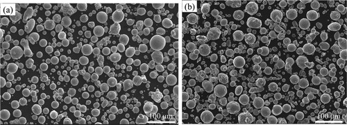
The mixed powder of CoCrCuFeNi HEA was obtained by mixing the pre-alloyed CoCrFeNi powder (particle sizes: 15–53 μm) and Cu powder (particle size: 15–53 μm) at the weight ratio of 451:127. The mixed powder of Al0.8CoCrCuFeNi HEA was obtained by mixing the pre-alloyed CoCrFeNi powder, Cu powder and Al powder (particle size: 15–53 μm) at the weight ratio of 451:127:43. In order to ensure uniform powder mixing, the powder is mixed in a ball mill for 12 h before LPBF. shows the CoCrFeNiCu powders and Al0.8CoCrFeNiCu powders after mixing. The powders still maintain a high degree of sphericity after mixing, ensuring the fluidity of the powder laying process during LPBF.
Figure 1. (a) SEM image of mixed CoCrFeNiCu powders; (b) SEM image of mixed Al0.8CoCrFeNiCu powders.
HEA blocks were fabricated by LPBF equipment (ProX DMP 200, 3D Systems, USA) with a laser spot diameter of 50 μm. During the LPBF process, the laser scanning path was rotated for 67° after each layer. This scanning strategy reduces the surface roughness, improves the surface quality, and reduces the residual stress. VED takes into account the laser parameters (P, v, h, t) and is defined as [Citation33]: VED = P/(vht), where P, v, h and t are laser power, scanning velocity, hatch spacing and layer thickness, and the process parameters are shown in .
Table 1. Processing parameters for fabricating the HEA blocks in this study.
X-ray diffraction (XRD) was performed using a Rigaku Smartlab X-ray diffractometor equipped with Cu Kα radiation. The microstructures of the samples were examined using a scanning electron microscope (SEM, JEOL JSM-6510A, and 7100F) equipped with an X-ray energy dispersive spectrometer (EDS) and electron backscattered diffraction (EBSD) detector. Hardness test was carried out with Vickers hardness tester, the test load was 200 gf and the pressure holding time was 15s. The cylindrical samples with a diameter of 3 mm and a height of 5 mm were tested at room temperature on Shimadzu AG-X-plus universal mechanics test machine with an initial strain rate of 5 × 10⁻⁴ s−1.
Microstructure of CoCrCuFeNi HEA
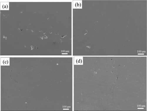
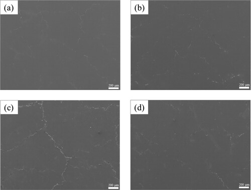
In order to better observe the surface quality and microstructures of the samples, the X-Y plane of CoCrCuFeNi HEAs with different VEDs were observed by SEM, as shown in . When the VED is 60 J/mm3, the viscosity and surface tension of the melt are high, and this leads to poor fluidity and wetting of the melt to the unmelted powder particles in the powder bed. This causes formation of large pores and unfused areas in the printed material. When the VED is 80 J/mm3, the area of the unfused area is reduced and the number of defects is reduced, and the surface quality is higher. When the VED is 120 and 160 J/mm3, the higher laser power and lower scanning velocity make the local temperature large, reduce the molten pool tension, and improve the fluidity of the molten pool. The high temperature makes the sufficient liquid phase fully diffuse, which is conducive to layer-by-layer bonding and the densification effect is better. However, the high energy density leads to the formation of keyholes in the molten pool. At the same time, the high temperature makes the unstable molten pool splash, resulting in gas more easily trapped in the melt, so that defects appear in the solidification process. Therefore, large pore defects only appear when the VED is low (60 J/mm3), and when the VED is 160 J/mm3, there are more cracks caused by thermal stress. When the VED is 80 J/mm3, there are fewer large pore defects and thermal cracks on the surface of the sample, and the quality is the best.
Figure 2. SEM images of microstructures of CoCrCuFeNi HEAs with different VEDs: (a) VED = 60 J/mm3; (b) VED = 80 J/mm3; (c) VED = 120 J/mm3; (d) VED = 160 J/mm3.
shows the EDS images at the pore defect of CoCrCuFeNi HEAs when the VED is 60 J/mm3. EDS results show that the unmelted metal powders are CoCrFeNi alloy powders, because CoCrFeNi alloy powders have the higher melting point, and when the VED is low, the pre-alloy powders with a high melting point cannot be completely melted, resulting in large pore defects during solidification.
Figure 3. The EDS map scanning results of CoCrCuFeNi HEAs around the pore (60 J/mm3).
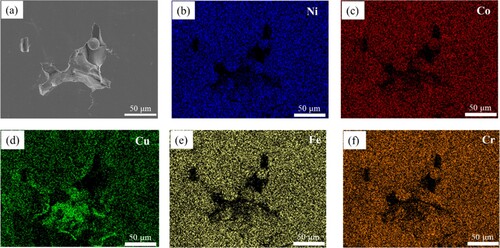
As can be seen from , Cu enrichment occurs in LPBF samples at the crack, and other elements are evenly distributed in areas away from the crack. It is suggested that the cause of the crack may be related to the severe segregation of Cu element. In the LPBF process, the cooling rate of the molten pool is very fast, and the temperature gradient is large, resulting in high residual stress. The melting point of Cu is the lowest among the mixed powders, and the solidification time is the longest, so it is easier to enrich in the grain boundary, so the Cu-rich liquid film will be formed. When the residual stress exceeds the maximum bearing limit of the liquid film, the liquid film will be torn and become a liquidation crack. At the same time, during the rapid growth of the grains, the heavier Cu atoms do not have enough time to complete the diffusion and alloying, and due to the poor solubility of Cu with other elements, it is easier to enrich, resulting in low strength at the segregation of Cu elements.
Figure 4. The EDS map scanning results of CoCrCuFeNi HEAs at crack (160 J/mm3).
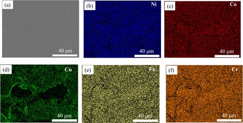
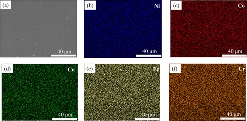
presents the EDS images of CoCrCuFeNi HEAs with the VED of 80 J/mm3 in the crack-free area. The results show that every element is evenly distributed on the surface of the alloy without defects, and no element segregation occurs.
Figure 5. The EDS map scanning results of CoCrCuFeNi HEAs in the crack-free area (80 J/mm3).
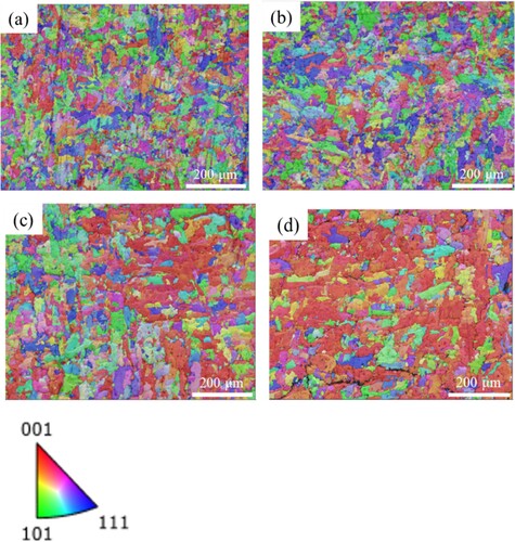
In order to analyze the grain characteristics of CoCrCuFeNi HEAs with different VEDs, EBSD was performed, and the results were shown in . The results show that the VEDs have little effect on the grain size, and the average grain size at each energy density is about 12 μm. With the increase of energy density, the <001> directional texture becomes more significant. The reason for this is that variation in VED has a notable impact on the molten pool's shape and dimensions, thereby influencing grain epitaxial growth and ultimately determining the preferred grain orientation. In the FCC phase, the IPF exhibits a prominent <001> texture, which is justifiable. This <001> orientation aligns with the preferential growth direction along the thermal gradient in FCC crystals [Citation34]. Consequently, during solidification, the FCC phase crystal grains exhibit the highest heat flux in the <001> orientation, resulting in the overgrowth of improperly positioned grains.
Figure 6. EBSD images of CoCrCuFeNi HEAs with different VEDs: (a) VED = 60 J/mm3; (b) VED = 80 J/mm3; (c) VED = 120 J/mm3; (d) VED = 160 J/mm3.
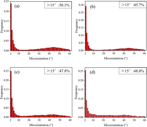
An important indicator of grain characteristics is the grain boundary misorientation [Citation35]. In order to further analyze the crystal structure inside the materials, EBSD technology was used to measure the misorientation distribution of alloy samples with different VEDs. shows the misorientation distribution of CoCrCuFeNi HEAs with different VEDs. With the increase of VEDs, the volume fraction of high-angle grain boundaries first decreases and then increases, among which the volume fraction of high-angle grain boundaries of the sample with 80 J/mm3 is the smallest. In the subsequent mechanical properties test, the results also show that the comprehensive performance of the sample with 80 J/mm3 is the best.
Figure 7. Distribution of grain boundaries of CoCrCuFeNi HEAs with different VEDs: (a) VED = 60 J/mm3; (b) VED = 80 J/mm3; (c) VED = 120 J/mm3; (d) VED = 160 J/mm3.
In the single-phase FCC structure, the probability of crack formation in the grain boundary with large misorientation is greater than that of the grain boundary with small misorientation, that is the cracking tendency of the alloy increases with the increase of the grain boundary misorientation, because the density of the solid phase is larger than that of the liquid phase, and the melt will produce a certain degree of volume contraction when it solidifies, resulting in a contraction force perpendicular to the grain boundary and opposite to the expansion direction of the grain boundary, forcing the separation of adjacent grains. At the same time, the flowing melt continues to fill the pores between the grains. When the grain growth is not enough to make up for the pores between grains caused by solidification contraction, cracks will appear at the grain boundaries. The larger the misorientation of the grain boundary, the greater the difference of solidification contraction degree between adjacent grains, which will aggravate the appearance and extension of cracks. Another reason for cracks extending along the grain boundaries is that the grain boundaries will hinder the dislocation movement, and dislocation accumulation will occur at the grain boundaries and lead to stress concentration. When the stress value exceeds the grain boundary strength, the crack will appear and spread along the grain boundaries.
Microstructure of Al0.8CoCrCuFeNi HEA
According to the valence electron concentration (VEC) criterion [Citation36], Al can stabilize the BCC structure, and the addition of Al will promote the transition from FCC to BCC structure. Therefore, alloy composition was adjusted from CoCrCuFeNi to Al0.8CoCrCuFeNi in this part. Due to the high crack sensitivity brought by Al, Al0.8CoCrCuFeNi HEAs are more brittle than CoCrCuFeNi HEAs, and the process window is narrower in the LPBF process. Therefore, the process is optimized and the VEDs are designed to be 100, 120, 139 and 167 J/mm3, respectively. The Al0.8CoCrCuFeNi HEAs with good surface quality were successfully prepared by LPBF method, and the effects of VEDs on the microstructures of Al0.8CoCrCuFeNi alloy will be discussed in the following sections.
shows the XRD patterns of Al0.8CoCrCuFeNi HEAs and CoCrCuFeNi HEAs with different VEDs. The comparison of Al0.8CoCrCuFeNi HEAs fabricated by LPBF with CoCrCuFeNi HEAs shows that the alloys change from FCC single-phase to FCC + BCC dual-phase structure, and the lattice constant increases and the diffraction peak shifts to the left due to the addition of Al with larger atomic radius. The comparison of Al0.8CoCrCuFeNi with different VEDs shows that with the increase of VEDs, the area of peaks of BCC phase decreases, indicating that the relative content of BCC phase decreases, and the diffraction peak shifts to the right, indicating that the lattice constant decreases. The reason for this phenomenon is that compared with other elements, Al element has the lowest boiling point (2327°C) and the smallest heat of vaporization (291.4 kJ/mol), and the instantaneous maximum temperature of the molten pool is 2000–3000°C. Therefore, the instantaneous high temperature of the molten pool leads to Al volatilization, and the higher the VEDs, the higher the volatilization rate of Al. Due to the low VEC of Al, the formation of BCC phase in Al0.8CoCrCuFeNi HEA is promoted. shows the content of each element in HEA with different VEDs. Therefore, the volatilization of Al weakens the formation effect of BCC phase, and the content of BCC phase decreases with the increase of VEDs. Another reason why the BCC phase decreases with the increase of VEDs is that at higher temperatures, the FCC phase has a lower Gibbs free energy [Citation37], which is the more stable state in the system, and the high VEDs promote the formation of more FCC phases.
Figure 8. XRD patterns of AlxCoCrCuFeNi (x = 0, 0.8) HEAs with different VEDs.
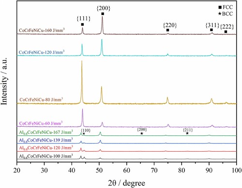
Table 2. Content of each element in Al0.8CoCrCuFeNi HEA samples.
As can be seen in , the SEM images show that more cracks appear after the addition of Al, and it is difficult to reduce the number of cracks by adjusting the process parameters. During the LPBF process, the molten pool underwent repeated solidification and remelting, resulting in higher thermal stress. Because the number of dislocation slip systems of the BCC structure is less than that of the FCC structure, the brittleness tendency of the BCC phase is greater, which is not conducive to coordinating the thermal stress generated in the process of repeated thermal cycling. Therefore, the number of cracks of the dual-phase HEAs after adding Al is more than that of the single-phase FCC HEAs, which indicates that Al0.8CoCrCuFeNi HEAs may be the crack sensitive materials.
Figure 9. SEM images of the surface of Al0.8CoCrCuFeNi HEAs with different VEDs: (a) VED = 100 J/mm3; (b) VED = 120 J/mm3; (c) VED = 139 J/mm3; (d) VED = 167 J/mm3.
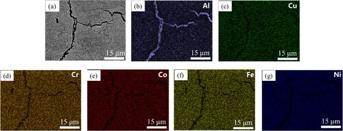
shows the EDS images of Al0.8CoCrCuFeNi sample with VED of 167 J/mm3, showing Al enrichment at the crack. During the solidification process, the solubility of Al decreases with the decrease of temperature, and the melting point of Al is the lowest and the solidification time is the longest, which leads to the enrichment of Al at the grain boundaries or dendritic boundaries and promotes the formation of liquid films at the grain boundaries. Due to the instantaneous heating and rapid cooling in the LPBF process, the large temperature gradient will lead to the high thermal stress in the alloy, which will be retained as a residual stress after the alloy solidification. When the stress exceeds the bearing range of the liquid films, the Al-rich liquid films will be torn and develop into the liquation cracks.
Figure 10. The SEM image and EDS elemental maps showing the liquation cracks of Al0.8CoCrCuFeNi HEA fabricated with 167 J/mm3.
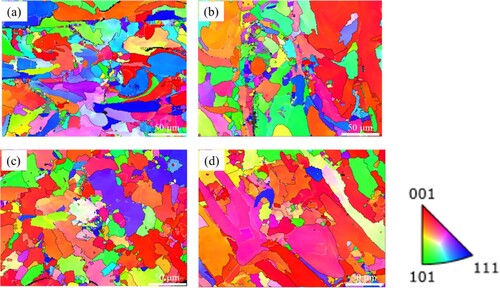
displays the EBSD images of Al0.8CoCrCuFeNi HEAs with different VEDs. The results show that the VEDs have little effect on the grain size, and the average grain size of each sample is about 9.5 μm. With the increase of VEDs, the <001> direction texture is more significant. In addition, with the increase of VEDs, the volume fraction of high-angle grain boundaries first increases and then decreases. Compared with FCC single-phase structure, the phase boundaries of FCC + BCC dual-phase structure are more chaotic, and the difference of grain growth is greater, so the volume fraction of high-angle grain boundaries are higher than that of CoCrCuFeNi HEAs.
Figure 11. The EBSD images of Al0.8CoCrCuFeNi HEAs with different VEDs: (a) VED = 100 J/mm3; (b) VED = 120 J/mm3; (c) VED = 139 J/mm3; (d) VED = 167 J/mm3.
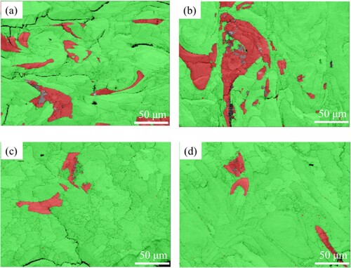
shows the distribution of FCC phase and BCC phase of Al0.8CoCrCuFeNi HEAs with different VEDs. In the figure, the red area is the BCC phase, and the green area is the FCC phase. It can be seen that the shape of the BCC phase is irregular, and the size and distribution are not uniform. As the VEDs increase, the content of the BCC phase decreases.
Figure 12. Distribution of FCC phase and BCC phase of Al0.8CoCrCuFeNi HEAs with different VEDs (Green area: FCC phase; Red area: BCC phase); (a) VED = 100 J/mm3; (b) VED = 120 J/mm3; (c) VED = 139 J/mm3; (d) VED = 167 J/mm3.
Mechanical properties
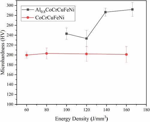
depicts the microhardness of AlxCoCrCuFeNi (x = 0, 0.8) HEAs as functions of VED. It can be seen that with the increase of VEDs, the microhardness of CoCrCuFeNi HEAs first increases and then decreases. Among them, the sample with the VED of 80 J/mm3 has the highest microhardness, which is 203 HV. Compared with the microhardness of CoCrCuFeNi HEA prepared by vacuum arc melting (∼ 161 HV) [Citation38], there is a significant improvement. Compared with the traditional method, the advantage of LPBF is mainly reflected in the characteristics of rapid cooling, which makes the grains significantly refined. Due to the fine grain size, the grain boundary density per unit volume is very high. The dislocation movement is hindered by the grain boundaries, and the dislocation gathers around the grain boundaries to form the dislocation cell, which improves the hardness of the materials. At the same time, due to the rapid solidification of the LPBF process, a large number of dislocations are formed. When the dislocations move, the dislocations intersect each other, form cut steps and cause dislocation entanglement, so that the movability of the dislocations is greatly reduced, increasing the deformation resistance of the materials, and the hardness is significantly improved. As can be seen from , the microhardness of Al0.8CoCrCuFeNi HEA samples ranges from 230 to 290 HV, which is significantly higher than that of CoCrCuFeNi HEA. In addition, the microhardness of the Al0.8CoCrCuFeNi HEA fabricated by LPBF is also higher than that of as-cast Al0.8CoCrFeNiCu HEA [Citation1].
Figure 13. Microhardness of AlxCoCrCuFeNi (x = 0, 0.8) HEAs with different VEDs.
exhibits the compressive stress–strain curves of AlxCoCrCuFeNi (x = 0, 0.8) HEAs with different VEDs. With the increase of VEDs, the yield strength of CoCrCuFeNi HEAs first increases and then decreases. The yield strength of CoCrCuFeNi HEAs with the VED of 80 J/mm3 is the highest, reaching 520 MPa. In general, the CoCrCuFeNi HEAs exhibit good ductility, but the strength is not high enough.
Figure 14. Engineering stress-strain curves of AlxCoCrCuFeNi (x = 0, 0.8) HEAs with different VEDs.
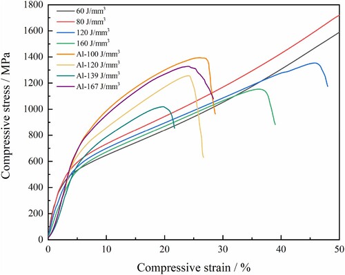
With regard to the Al0.8CoCrCuFeNi HEAs, due to the higher hardness of BCC phase and the more slip systems of FCC phase, so during the deformation process, hard phase BCC will bear more stress, while soft phase FCC will bear more strain. The FCC phase can release the stress through the slip of the dislocation, thus alleviating the stress concentration in the dual-phase zone. As can be seen from , with the increase of VEDs, the yield strength of Al0.8CoCrCuFeNi HEAs first decreases and then increases, and the yield strength of Al0.8CoCrCuFeNi HEAs is significantly higher than that of CoCrCuFeNi HEAs, and good ductility can be maintained. The yield strength of Al0.8CoCrCuFeNi HEA with VED of 167 J/mm3 is 652 MPa, showing the best performance.
During the compression process, the soft FCC phase first undergoes plastic deformation, and the BCC phase undergoes elastic deformation. At the same time, the FCC/BCC phase boundaries become the barriers to dislocation movement, and a large number of dislocations in the FCC phase cannot be transferred to the BCC phase, resulting in back stress. Since the strain at the FCC/BCC phase boundaries is continuous, plastic strain gradient appears at the FCC phase in the soft region near the boundaries. With the intensification of plastic deformation, the strain gradient will continue to increase, resulting in significant back stress strengthening. When compressive stress is continuously applied to the sample, dislocation accumulation at the boundaries of FCC phases induces strain-hardening at the boundary regions, which can activate dislocation nucleation and slip operate in the adjacent BCC regions [Citation39]. Another important reason for strengthening is that Al atoms with large atomic radius in the solid solution cause lattice distortion, increase the resistance of dislocation movement, resulting in difficult dislocation slip, and enhance the effect of solid solution strengthening. Solid solution strengthening is one of the mechanisms of strength improvement after adding Al [Citation34,Citation40].
Effects of heat treatment
Because of high cooling rate and large temperature gradient, large residual stress is generated in the LPBF-fabricated samples. Heat treatment can not only effectively eliminate the residual stress, but also facilitate precipitation of second phase [Citation41], and significantly improve the mechanical properties of HEAs. Therefore, the Al0.8CoCrCuFeNi HEAs fabricated with the VED of 167 J/mm3 were annealed at 600 and 900°C respectively for 1 h.
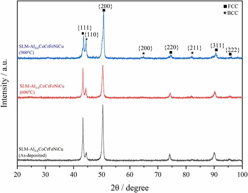
depicts the XRD results of the as-deposited Al0.8CoCrCuFeNi HEAs following different heat treatments. It can be seen that the heat treatment temperature has a great influence on the phase composition of the HEAs. For the annealed samples, the FCC and BCC phases can be detected. With increasing annealing temperature, the relative intensity for {111} diffraction peak of the FCC phase decreases and {110} diffraction peak of the BCC phase continuously increases, indicating that the phase transformation from FCC to BCC may occur in the sample. At the same time, with the increase of annealing temperature, the diffraction peak of FCC moves to the right, indicating that the lattice constant of the alloy decreases.
Figure 15. XRD patterns of the as-deposited Al0.8CoCrCuFeNi HEAs after annealing treatment.
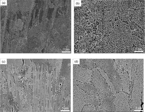
The SEM results of the as-deposited Al0.8CoCrCuFeNi HEAs subjected to annealing treatments at various temperatures are shown in . (a,b) show the X-Y plane of the samples. After annealing at 600°C for 1 h, the cellular structure of the sample is similar to that of the as-deposited Al0.8CoCrCuFeNi HEAs and some precipitates can be seen at the cell boundaries. The microstructure of the X-Y plane of the sample after annealing at 900°C for 1 h has a significant change compared with the as-deposited sample. The SEM images of the X-Z plane of Al0.8CoCrCuFeNi HEAs annealed at 600°C and 900°C for 1 h are shown in (c,d). Due to the high cooling rate and large undercooling in the LPBF process, there is a large temperature gradient perpendicular to the laser scanning direction at the molten pool boundary. The crystal growth is parallel to the maximum temperature gradient direction, resulting in the columnar grains or dendrites to be perpendicular to the molten pool boundary. At the same time, it can be seen that precipitates appear between the columnar crystals. It can be seen from (d) that the morphology of X-Z plane of the Al0.8CoCrCuFeNi HEA annealed at 900°C for 1 h is similar to the X-Y plane, and the typical columnar crystal morphology of the additive manufacturing disappears. In addition, the amount of precipitated phase is significantly reduced after annealing at 900°C, showing that the precipitated phase dissolved during annealing at 900°C.
Figure 16. SEM images of the as-deposited Al0.8CoCrCuFeNi HEAs after annealing treatment at different temperatures: (a) 600°C (X-Y plane); (b) 900°C (X-Y plane); (c) 600°C (X-Z plane); (d) 900°C (X-Z plane).
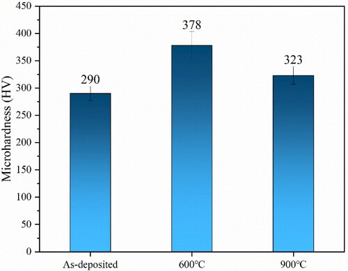
The microhardness of the as-deposited Al0.8CoCrCuFeNi HEA samples subjected to annealing treatments at various temperatures are shown in . The microhardness of the as-deposited Al0.8CoCrCuFeNi HEAs is 290 HV. Due to the formation of precipitates at the boundaries of cellular and columnar crystals, the Al0.8CoCrCuFeNi HEA annealed at 600°C for 1 h were strengthened, and the microhardness significantly increased to 378 HV, which was higher than the microhardness (304 HV) of the dual-phase HEA prepared by vacuum arc melting [Citation42]. However, when the annealing temperature reaches 900°C, due to the dissolution of precipitates and grain coarsening, the microhardness is reduced to 323 HV, but still higher than that of the as-deposited samples.
Figure 17. Microhardness of the as-deposited Al0.8CoCrCuFeNi HEAs after annealing treatment.
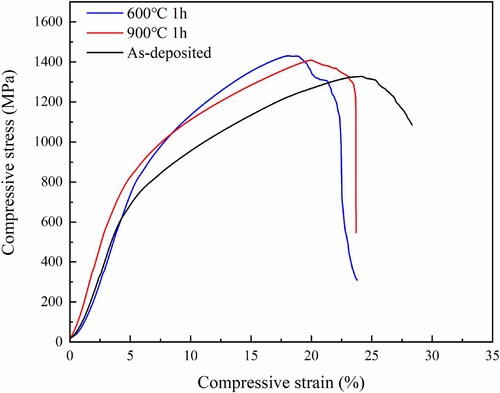
depicts the compressive engineering stress–strain curves of the Al0.8CoCrCuFeNi HEAs after annealing at different temperatures. It can be seen that compared with the as-deposited samples, the compressive properties of the Al0.8CoCrCuFeNi HEA samples annealed at 600°C and 900°C for 1 h has been significantly improved. Among them, the yield strength of the Al0.8CoCrCuFeNi HEAs annealed at 600°C for 1 h reached 810 MPa, which is the best performance and can maintain good ductility. After annealing at 900°C for 1 h, the yield strength slightly decreased due to the dissolution of precipitates and grain coarsening.
Figure 18. Compressive engineering stress-strain curves of the as-deposited and heat treated Al0.8CoCrCuFeNi HEAs.
Based on the above analysis, it can be concluded that the microhardness and compressive properties of Al0.8CoCrCuFeNi HEA have been significantly enhanced after annealing at 600°C. Because the boundaries of the cellular structure can hinder the movement of dislocations, the precipitates distributed along the grain boundaries enhance the ability of grain boundaries to hinder the movement of dislocations. At the same time, the dislocation lines bend and form dislocation loops, which further increase the resistance of dislocation movement. In addition, the solid solution of alloying elements causes severe lattice distortion in the FCC phase, hindering the slip of dislocations and further improving the strength of the alloys. Therefore, the combined effects of precipitation strengthening and solid solution strengthening significantly improves the properties of the alloy annealed at 600°C for 1 h.
Conclusions
In this study, AlxCoCrCuFeNi (x = 0, 0.8) HEAs were successfully prepared by LPBF. The effects of different VEDs and heat treatment on the microstructures, relative density, microhardness and compression properties of HEAs were investigated. The following conclusions can be drawn:
In the CoCrCuFeNi HEAs, the defects of unfused areas appear when the VED is too low, while high VED will result in thermal cracking. When the VED is 80 J/mm3, the samples show fewer defects, the best forming quality, the lowest volume fraction of high-angle grain boundaries, and the sample exhibits the highest yield strength (520 MPa).
After the alloy composition was adjusted from CoCrCuFeNi to Al0.8CoCrCuFeNi, the sample changed from FCC single phase to FCC + BCC dual-phase structure. The microhardness of Al0.8CoCrCuFeNi HEAs are significantly improved, and the yield strength is increased from 520 MPa to 652 MPa. The Al0.8CoCrCuFeNi HEAs have a dual-phase structure of soft phase FCC and hard phase BCC, and the coordinated deformation between the two phases, back stress strengthening and solid solution strengthening make the alloys higher strength and ductility.
Among the as-deposited Al0.8CoCrCuFeNi HEAs, the sample with VED of 167 J/mm3 shows the best comprehensive properties. After annealing at 600°C for 1 h, the microhardness (378 HV) and yield strength (810 MPa) of the Al0.8CoCrCuFeNi HEAs are significantly increased, which is attributed to precipitation strengthening and solid solution strengthening.
Disclosure statement
No potential conflict of interest was reported by the author(s).
Additional information
Funding
References
- Ye JW, Chen SK, Lin SJ, et al. Nanostructured high-entropy alloys with multiple principal elements: novel alloy design concepts and outcomes. Adv Eng Mater. 2004;6:299–303. doi:10.1002/adem.200300567
- Cantor B, Chang IT, Knight P, et al. Microstructural development in equiatomic multicomponent alloys. Mater Sci Eng A. 2004;375-377:213–218. doi:10.1016/j.msea.2003.10.257
- Dobbelsteina H, Gurevicha EL, George EP, et al. Laser metal deposition of compositionally graded TiZrNbTa refractory high-entropy alloys using elemental powder blends. Addit Manuf. 2019;25:252–262. doi:10.1016/j.addma.2018.10.042
- Miracle DB, Senkov ON. A critical review of high entropy alloys and related concepts. Acta Mater. 2017;122:448–511. doi:10.1016/j.actamat.2016.08.081
- Cieslak G, Stygar M, Mroczka K, et al. Influence of Cu content on high temperature oxidation behavior of AlCoCrCuxFeNi high entropy alloys (x = 0; 0.5; 1). Intermetallics. 2017;84:52–61. doi:10.1016/j.intermet.2016.12.015
- Lu J, Chen Y, Zhang H, et al. Effect of Al content on the oxidation behavior of Y/Hf-doped AlCoCrFeNi high-entropy alloy. Corros Sci. 2020;170:108691. doi:10.1016/j.corsci.2020.108691
- Yao MJ, Pradeep KG, Tasan CC, et al. A novel, single phase, non-equiatomic FeMnNiCoCr high-entropy alloy with exceptional phase stability and tensile ductility. Scr Mater. 2014;72-73:5–8. doi:10.1016/j.scriptamat.2013.09.030
- Wei XR, Zhang PL, Yu ZS, et al. Effect of phase transformation on mechanical properties of Al16.80Co20.74Cr20.49Fe21.28Ni20.70 high entropy alloy coatings processed by laser cladding. J Alloys Compd. 2021;862:158563. doi:10.1016/j.jallcom.2020.158563
- Fujieda T, Shiratori H, Kuwabara K, et al. CoCrFeNiTi-based high-entropy alloy with superior tensile strength and corrosion resistance achieved by a combination of additive manufacturing using selective electron beam melting and solution treatment. Mater Lett. 2017;189:148–151. doi:10.1016/j.matlet.2016.11.026
- Yin B, Maresca F, Curtin WA. Vanadium is an optimal element for strengthening in both fcc and bcc high-entropy alloys. Acta Mater. 2020;188:486–491. doi:10.1016/j.actamat.2020.01.062
- Zhou R, Liu Y, Liu B, et al. Precipitation behavior of selective laser melted FeCoCrNiC0.05 high entropy alloy. Intermetallics. 2019;106:20–25. doi:10.1016/j.intermet.2018.12.001
- He JY, Wang Q, Zhang HS, et al. Dynamic deformation behavior of a face-centered cubic FeCoNiCrMn high-entropy alloy. Sci Bull. 2018;63:362–368. doi:10.1016/j.scib.2018.01.022
- Li RD, Niu PD, Yuan TC, et al. Selective laser melting of an equiatomic CoCrFeMnNi high-entropy alloy: processability, non-equilibrium microstructure and mechanical property. J Alloys Compd. 2018;746:125–134. doi:10.1016/j.jallcom.2018.02.298
- Chew Y, Bi GJ, Zhu ZG, et al. Microstructure and enhanced strength of laser aided additive manufactured CoCrFeNiMn high entropy alloy. Mater Sci Eng A. 2019;744:137–144. doi:10.1016/j.msea.2018.12.005
- Zhou PF, Xiao DH, Wu Z, et al. Al0.5FeCoCrNi high entropy alloy prepared by selective laser melting with gas-atomized pre-alloy powders. Mater Sci Eng A. 2019;739:86–89. doi:10.1016/j.msea.2018.10.035
- Zhang MN, Zhou XL, Wang DF, et al. Alcocufeni high-entropy alloy with tailored microstructure and outstanding compressive properties fabricated via selective laser melting with heat treatment. Mater Sci Eng A. 2019;743:773–784. doi:10.1016/j.msea.2018.11.118
- Niu PD, Li RD, Yuan TC, et al. Microstructures and properties of an equimolar AlCoCrFeNi high entropy alloy printed by selective laser melting. Intermetallics. 2019;104:24–32. doi:10.1016/j.intermet.2018.10.018
- Li FZ, Wang ZM, Zeng XY. Microstructures and mechanical properties of Ti6Al4V alloy fabricated by multi-laser beam selective laser melting. Mater Lett. 2017;199:79–83. doi:10.1016/j.matlet.2017.04.050
- Kuwabara K, Shiratori H, Fujieda T, et al. Mechanical and corrosion properties of AlCoCrFeNi high-entropy alloy fabricated with selective electron beam melting. Addit Manuf. 2018;23:264–271. doi:10.1016/j.addma.2018.06.006
- Lu YP, Dong Y, Guo S, et al. A promising new class of high-temperature alloys: eutectic high-entropy alloys. Sci Rep. 2014;4:1–5.
- Li N, Zhang JJ, Xing W, et al. 3D printing of Fe-based bulk metallic glass composites with combined high strength and fracture toughness. Mater Des. 2018;143:285–296. doi:10.1016/j.matdes.2018.01.061
- Asoushe MH, Zarei Hanzaki A, Abedi H R, et al. Thermal stability, microstructure and texture evolution of thermomechanical processed AlCoCrFeNi2.1 eutectic high entropy alloy. Mater Sci Eng A. 2021;799:140012. doi:10.1016/j.msea.2020.140012
- Karimi J, Ma P, Jia YD, et al. Linear patterning of high entropy alloy by additive manufacturing. Manuf Lett. 2020;24:9–13. doi:10.1016/j.mfglet.2020.03.003
- Gwalani B, Soni V, Choudhuri D, et al. Stability of ordered L12 and B2 precipitates in face centered cubic based high entropy alloys – Al0.3CoFeCrNi and Al0.3CuFeCrNi2. Scr Mater. 2016;123:130–134. doi:10.1016/j.scriptamat.2016.06.019
- Lu YP, Gao XZ, Jiang L, et al. Directly cast bulk eutectic and near-eutectic high entropy alloys with balanced strength and ductility in a wide temperature range. Acta Mater. 2017;124:143–150. doi:10.1016/j.actamat.2016.11.016
- Yu WH, Sing SL, Chua CK, et al. Particle-reinforced metal matrix nanocomposites fabricated by selective laser melting: a state of the art review. Prog Mater Sci. 2019;104:330–379. doi:10.1016/j.pmatsci.2019.04.006
- Fujieda T, Chen M, Shiratori H, et al. Mechanical and corrosion properties of CoCrFeNiTi-based high-entropy alloy additive manufactured using selective laser melting. Addit Manuf. 2019;25:412–420. doi:10.1016/j.addma.2018.10.023
- Xia MJ, Gu DD, Yu GQ, et al. Selective laser melting 3D printing of Ni-based superalloy: understanding thermodynamic mechanisms. Sci Bull. 2016;61:1013–1022. doi:10.1007/s11434-016-1098-7
- Brif Y, Thomas M, Todd I. The use of high-entropy alloys in additive manufacturing. Scr Mater. 2015;99:93–96. doi:10.1016/j.scriptamat.2014.11.037
- Zhu ZG, Nguyen QB, Ng FL, et al. Hierarchical microstructure and strengthening mechanisms of a CoCrFeNiMn high entropy alloy additively manufactured by selective laser melting. Scr Mater. 2018;154:20–24. doi:10.1016/j.scriptamat.2018.05.015
- Luo SC, Zhao CY, Su Y, et al. Selective laser melting of dual phase AlCrCuFeNix high entropy alloys: formability, heterogeneous microstructures and deformation mechanisms. Addit Manuf. 2020;31:100925. doi:10.1016/j.addma.2019.100925
- He L, Wu SW, Dong AP, et al. Selective laser melting of dense and crack-free AlCoCrFeNi2.1 eutectic high entropy alloy: synergizing strength and ductility. J Mater Sci Technol. 2022;117:133–145. doi:10.1016/j.jmst.2021.11.049
- Kim J, Wakai A, Moridi A. Materials and manufacturing renaissance: additive manufacturing of high-entropy alloys. J Mater Res. 2020;35:1963–1983. doi:10.1557/jmr.2020.140
- Peyrouzet F, Hachet D, Soulas R, et al. Selective laser melting of Al0.3CoCrFeNi high-entropy alloy: printability, microstructure, and mechanical properties. J Miner Metals Mater Soc. 2019;71:3443–3451. doi:10.1007/s11837-019-03715-1
- Wang B, Lei BB, Zhu ZX, et al. EBSD study on microstructure and texture of friction stir welded AA5052-O and AA6061-T6 dissimilar joint. Mater Des. 2015;87:593–599. doi:10.1016/j.matdes.2015.08.060
- Guo S, Ng C, Lu J, et al. Effect of valence electron concentration on stability of fcc or bcc phase in high entropy alloys. J Appl Phys. 2011;109:103505. doi:10.1063/1.3587228
- Wang Y, Li RD, Niu PD, et al. Microstructures and properties of equimolar AlCoCrCuFeNi high-entropy alloy additively manufactured by selective laser melting. Intermetallics. 2020;120:106746. doi:10.1016/j.intermet.2020.106746
- Liu Y, Chen M, Li YX, et al. The microstructure and mechanical properties of AlxCoCrCuFeNi multi principal component high entropy alloy. Rare Met Mater Eng. 2009;38:1602–1607.
- Wu SW, Wang G, Wang Q, et al. Enhancement of strength-ductility trade-off in a high-entropy alloy through a heterogeneous structure. Acta Mater. 2019;165:444–458. doi:10.1016/j.actamat.2018.12.012
- Karlsson D, Marshal A, Johansson F, et al. Elemental segregation in an AlCoCrFeNi high-entropy alloy – a comparison between selective laser melting and induction melting. J Alloys Compd. 2019;784:195–203. doi:10.1016/j.jallcom.2018.12.267
- Wu SW, Chia HY, Zhang TL, et al. A precipitation strengthened high entropy alloy with high (Al+Ti) content for laser powder bed fusion: synergizing in trinsic hot cracking resistance and ultrahigh strength. Acta Mater. 2023;258:119193. doi:10.1016/j.actamat.2023.119193
- Xu J, Zhang JY, Wang YQ, et al. Annealing-dependent microstructure, magnetic and mechanical properties of high-entropy FeCoNiAl0.5 alloy. Mater Sci Eng A. 2020;776:139003. doi:10.1016/j.msea.2020.139003