 ?Mathematical formulae have been encoded as MathML and are displayed in this HTML version using MathJax in order to improve their display. Uncheck the box to turn MathJax off. This feature requires Javascript. Click on a formula to zoom.
ABSTRACT
The structural behaviour of Glass Fibre Reinforced Polymer (GFRP) retrofitted reinforced concrete beam in addition with Nano admixtures (NA) was experimentally investigated and analysed. Globally, a large number of structures are subjected to unanticipated damages and deterioration. To renovate such buildings to serviceable state, repairing and retrofitting of damaged structures is the viable and economical option. This investigation aims to improve the resistance to flexure for reinforced beam by enhancing the mechanical properties concrete with the addition of various combinations of Nano admixtures (NA) as Nano silica (NS) and Nano clay (NC) and retrofitting the same. The void filling property of Nano admixtures produced a dense concrete with minimum voids in the concrete mass and improved the mechanical properties. To analyse the influence of Nano admixture, SEM analysis was done and the micro structure of the concrete mix was studied and analysed the microstructural features of the concrete. The structural mechanism of beams before and after wrapped with two layers of GFRP sheets was experimentally verified by this study.
1. Introduction
Concrete, a composite material is considered the most used construction material because of its versatility, durability and reliability. Concrete is rather a simple material consisting of water, fine aggregate, coarse aggregate and cement in prescribed mix proportioning. Modifications are made to concrete to achieve the enhancement in mechanical properties. When concrete is fresh, it forms a fluid mass which takes the shape of the mould in which it is placed, upon curing for the required time, the cement reacts with the added water to form a solid binder which binds the aggregates to form a hard and durable material with several uses. Shilar et al. (Citation2022) have explained the geopolymer concrete with greater structural performance, this research examines trends and technologies in the creation of various nanomaterials. The highest strength growth of geopolymer concrete resulted from the addition of a modest number of nanoparticles, specifically nano silica, nano alumina, carbon nano tubes, and nano clay (Shinde et al., Citation2014; Ugale Ashish & Raut Harshalata, Citation2014; Venkatesha et al., Citation2012). The structural stability of the geopolymer is greatly improved and its endurance is increased by adding these nanoparticles. According to SEM, XRD, and FTIR investigations, the addition of highly reactive nanoparticles to GP composites results in a variety of products that improve the geopolymer’s performance. This accelerates the polymerization process.
The flexural behavior of a R.C.C. beam wrapped in GFRP (glass fiber reinforced polymer) sheet was studied by Shinde (Citation2022). There were a total of eight beams, each with an overall span of 700 mm and a cross \-section of (150×150) mm (Hagio et al., Citation2013). The examination concentrated on three main aspects: the strength, ductility, and degree of damage of the reinforced R.C.C. beam as well as the flexure weakness of the reinforced R.C.C. beam (Almusallam & Al-Salloum, Citation2010; Jaya & Mathai, Citation2012). In R.C.C. under reinforced beams, GFRP sheet was applied in a single layer from the tension face, which is parallel to the beam axis, and was tested under static loads until failure (Dave et al., Citation2014). Two of a set of flexure-weak beams were strengthened with GFRP sheet and tested to failure; the other two served as a control specimen. The outcomes of two sets have been compared. More and Kulkarni (Citation2014) have discussed the effects of strengthening on load carrying capacity as well as the impact of damage degree M.S Shetty [Citation1982-2018]. According to the findings, the number of layers greatly boosted the weight carrying capability of beams. ANSYS software was used to validate the experimental results. The specimens were simply subjected to a two point loading mechanism in order to evaluate the flexural behavior of the beam. Along the length of the bottom face of the beams, AFRP sheets were wrapped in single and double layers. The current work addresses the impact of the beam’s degree of damage as well as the impact of the number of layers according to the study of Kumar et al. (Citation2010) and Natarajan and Arun Kumar (Citation2009). As a result, it is a practical solution for RC beam strengthening and retrofitting.
2. Materials used
By altering the ingredients of concrete listed below, and by replacing the binder type and aggregate content, we can create a new strain of concrete suitable for the relevant application conditions as per the study maid by Shilar et al. (Citation2022), and IS: 456. (Citation2000).
2.1. Cement
The most important ingredient for concrete is cement, the strength and structural integrity of concrete are from the bound action between cement and aggregates. In early days, volcanic slag and crushed brick enhancements which were added to the burnt lime, to obtain a hydraulic binder, were later known to as cementum, cementum, and cement. Selection and usage of cement are according to provisions of IS: Citation4031-1968. and Punmia [Citation[2005-2016]]. Portland cement is manufactured by proportioning, crushing, milling of the following materials.
Alumina, Al2O3: from bauxite, recycled aluminium, clay
Oxides of calcium or Lime, CaO: from limestone, chalk, shells, shale or calcareous rock
Iron, Fe2O3: from clay, iron ore, scrap iron and fly ash
Silica, SiO2: from sand, clay or argillaceous rock
Gypsum, CaSO4.2 H2O: found together with limestone
2.2. Fine aggregate
Fine aggregate having the intermediate particle size when compared to cement and course aggregate plays a major role in the prevention of voids and provide workability to the concrete. It consists mainly of fine aggregate, crushed stone, or crushed slag screenings; on contrast, coarse aggregate consists of gravel (pebbles), fragments of broken stone, slag, and other coarse substances. Fine aggregates are identified by its particle size which passes through 4.75 mm sieve and predominately retained on the 75μsieve. Selection and usage of fine aggregate are according to provisions IS: 383.
2.3. Coarse aggregate
Coarse aggregates are identified by its particles size greater than 4.75 mm but generally range between 9.5 mm to 37.5 mm. The purpose of the coarse aggregate is to act as the main load bearing component of the concrete. The desirable properties of course aggregate are hardness and durability. Coarse aggregate of naturally occurring materials such as gravel are resulting from the crushing of parent rock, to include natural rock, slags, expanded clays and shale.
2.4. Water
The ratio of the minimum quantity of water required to the weight of the cement to obtain the desired concrete mix is called water cement ratio. The content of water mixed to manufacture concrete plays a major role in the formation of strength and prevention of problems related to excess water like segregation of aggregates, bleeding and shrinkage cracks. The optimum quantity of water is the key factor to achieve sufficient strength with adequate workability. Reduction of water increases trength of concrete and decreases workability. Water used for mixing should be clean, fresh and free from organic impurities.
2.5. Nano admixtures
Concrete is produced by the combination of different materials such as finely powdered cement, aggregates of various sizes and water which has its physical, chemical, and mechanical properties. The achievement of high strength is due to the formation of calcium silicates and some by-products including calcium hydroxide [CH], ‘gel pores’ during hydration reaction of cement. The rate of hydration reaction differs within the concrete mass and the surface which may lead to the formation of cracks and problems related to the crack formation.
Formation of cracks may also be associated with alkali-silica reaction which results in the formation of weak materials and eventually fissures due to premature erosion and cracks in concrete.
The reinforcement embedded in concrete maybe corroded by the reaction with the atmospheric gasses through porous concrete surface which may lead to spalling and cracks. Thermal variations leading to expansion and shrinkage in concrete may also cause cracks and deterioration.
Sulphate attack contributes to the failure and crack formation at later stages of the concrete, which causes crumbling in concrete. Moreover, chemical leaching which is closely related to sulphate attack is mainly due to the presence of excess calcium hydroxide [CH], which is the by-product of cement hydration represented by the following chemical reactions.
[Cement chemistry notation: C = CaO; S = SiO2; H = H2O]. From the above reactions, the formation of C-S-H forms amorphous substance which contributes strength to the concrete, however the by-product, CH does not have any cementitious properties, and can be easily leached out and prone to chemical attack. By adding suitable cementitious materials of siliceous or aluminous composition with cement, additional C-S-H will be produced by the reaction with CH and with the replacement of porous CH, the reaction alters the pore structure and prevents permeability of gases and liquid in concrete. The reduction of the porous CH content during cement hydration is associated with the prevention of possible sulphate attack and chemical leaching, which will prevent crack formation and increase the serviceability of the concrete.
Innovations in this aspect have risen to tackle this issue by using pozzolanic cementitious materials and chemicals. Additional C-S-H materialsare attained by chemical reactions of the CH to get supplementary product which provides additional pore filling mechanism. The additional cementitious materials such as fly ash, ground granulated blast furnace slag, condensed micro silica fume, rice husk ash, metakaolin etc., have been studied extensively in concrete as pozzolanic materials to enact the CH and get the additional C-S-H. The addition of supplementary cementitious materials in the concrete will not only improve the mechanical properties of concrete, workability and durability.
At this circumstance, the researchers are taking advantage of Nanotechnology to produce a novel generation of concrete materials that overcome the above weaknesses and trying to achieve the sustainable concrete structures. Development of materials is need of the day for enhanced or better performance for special engineering applications and modifying the bulk state of materials in terms of composition or microstructure or nanostructure has been the established route for synthesizing novel materials. The newer materials can also be obtained by smart and blending of existing materials at small level
The Nano admixtures used in this project are
Nano silica
Nano clay
2.6. Nano silica
The advantage of using Nano products in Civil Engineering applications has gained popularity in recent years. Nano silica (NS) is one of the most used Nano material. The replacement of silica by Nano silica proved to be much effective due to the fact that improved workability and durability were achieved by the Nano silica which is a pozzolanic material. The Nano silica reacts with the available free lime during the cement hydration and forms additional C-S-H gel which gives strength, in permeability and durability to concrete.
2.6.1. Applications
Contributing strength to the concrete
Filling the voids
Acceleration to the settings
Cement matrix densification
2.7. Nano clay
The shape and size of nano clay were studied for better a perceptive of its behaviour with concrete. The nano clay raw material with a plated structure is in the state of montmorillonite; a 2-to-1 layered smectite clay mineral. The nano size of Individual platelet has a thickness of just one nanometre (10−9 meter), high aspect ratio was observed due to the fact that surface dimensions are generally 300 to more than 600 nanometres. Obviously occurring montmorillonite is hydrophilic. The process of dispersion of raw nano clay in polymers are done with great difficulty since unmodified nano clay are generally organophilic. However modification of the surface of montmorillonite resulted in formation of organophilic which is compatible with conventional organic polymers. The process of modification of surface in order to make it compatible is known as ‘intercalation’
The raw nano clay used in this study was Metakaolin. The Metakaolin was modified to High-purity kaolinitic clays by calcination at fairly low temperature of 610–720° C to keep silica and alumina in amorphous state, then milled to particles smaller than 2 microns. The modified nano clay is a highly volatile pozzolana with white colour which maybe especially suitable for architectural concrete.
3. Experimental work
3.1. SEM analysis for nano admixtures
The micro structure of nano materials can be appropriately studied by a scanning electron microscope (SEM). Images of samples are produced by electron microscope that focuses beam of electrons which scans the sample. During the scanning process, the molecules in the sample interact with electrons which produce several signals that are detected with information about the sample’s surface topography and conformation. An image is formed by the combination of scan pattern and the beam’s position.
The resolution achieved by SEM can be better than 1 nanometre. Specimens can be observed in high vacuum, in low vacuum, in dry conditions (in environmental SEM), and at a widespread range of cryogenic or elevated detection is by minor electrons emitted by atoms excited by the electron beam. On a flat surface, the plume of secondary electrons is mostly contained by the sample, but on a tilted surface, the plume is partially temperatures by Shinde et al. (Citation2014).
The most common mode of exposed and more electrons are released. An image displaying the topography of the surface is created by scanning the sample and detecting the secondary electrons. Since the detector is not a camera, there is no deflection limit for resolution as in optical microscopes and telescopes.
3.2. SEM analysis on NS
Figure shows the SEM micrographs of NS. The SEM shows that the microstructure of the Nano silica is denser and more homogeneous than of the conventional cement because of the pozzolanic reaction by consumption of Ca (OH)2, the microstructure of concrete is widely recognized to play a significant impact in effective qualities such as strength and durability and formation an additional C-S-H which fill the pores system and causing densification effect which improves the microstructure of mortar. Proportionally to Parameter.
Figure 1. (a) scanning electron microscope image of NS of 50µ, (b) scanning electron microscope image of NS of 100µ.
3.3. SEM analysis on NC
From the SEM image as shown in Figure , the nano clay was shown as Nanoribbon with about several microns in length and about 200 nm in width. It was not hard to imagine when this kind of Nanoribbon was evenly distribute across the mortar, it would inter-lock and entangle with the polymer chains in the mortar.
Figure 2. (a) scanning electron microscope image of NC of 50µ, (b) scanning electron microscope image of NC of 100µ.
3.4. Mix proportion
The mix ratio effects of M35 grade concrete mixed with various proportions of Ce,ment, Fine aggregate, coarse aggregare of concrete, as per IS code 10262:2009 are shown in Tables .
Table 1. As per IS: 10262 (Citation2009): guidelines for concrete mix design for M35 grade concrete
4. Experimemtal works
According to IS 456–2000 code, the test is usually achieved on hardened cube specimens. It is uniaxial test where the compressive load is gradually increased till the specimen fails. In this experimental programme this test was accomplished on the concrete cube specimens of size 150 mm at early age and at full maturity in accordance with IS Citation516-1959. The compressive strength of the concrete was calculated as Compressive strength = Ultimate load at failure/Cross sectional area of the specimen. The strength characteristrict of Cement with Nano Clay and Nano Silica are expressed in Figure . The various optimum percentage of micro structural study based on SEM for Cement with Nano Clay and Nano Silica additives are presented in Figure . The Crushing load and cumulative strength of various combinations of concretre specimens with Nano Clay and Nano Silica additives are presented in Table .
Figure 3. a) and b) show the results of compressive strength of specimens. Cement replaced with Nano Clay and Nano Silica at a) 7th Day compressive strength. b) 28th Day compressive strength.
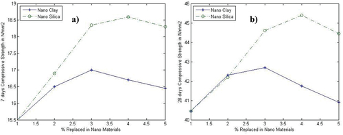
Figure 4. SEM images of concrete samples after 28 days of curing: (a,b,c,d). (a) conventional concrete, (b) concrete containing 4% NC and 0% NS.(c) concrete containing 2% NC and 4% NS and (d) concrete containing 0% NC and 4% NS.
Table 2. Compressive strength of concrete with cement replaced by nano clay and Nano silica
In this experimental programme the flexural strength tests were performed on the concrete beam specimens at early age and at full maturity in accordance with IS 516–1959. A Universal testing machine was used for flexural strength tests. Flexural strength test on beam specimens of OPC, nano admixture concrete and wrapped with GFRP was performed at 28 day of curing. The Crushing load and Flexural strength of various combinations of concretre specimens with Nano Clay and Nano Silica additives before and after retrofitting are presented in Table .
Table 3. Flexural strength of concrete beam with cement replaced by various percentage of NC and NS
5. Result and discussion
From the experimental Analysis it has been found that the conventional concrete of grade M35 has a compressive strength of 42.65 N/mm2. When we added NC as admixture it has been observed that the compressive strength will become maximum at 4% of replacement which is 44.25N/mm2 and the flexural strength of beam is increased more than 7% than the conventional beam. The compressive strength of the concrete reaches at maximum on 6% replacement of NS at an increment of 17% on flexural strength than the conventional beam. The compressive strength reaches its maximum when NC (admixture) of 2% is added. When the replacement is done by the mixing of NC and NS gives the flexural strength of 24% more than the CB (conventional beam) and the 4% of replacement of NC gives 8% more than the compressive strength, and the combination of 4% of NC with 2% of NS gives the same compressive strength as on conventional beam. The flexural strength increase when NS is added at the optimal replacement percentage of 2%. When we added NC as admixture it has been observed that the flexural strength will become maximum at 4% of replacement which is 11.20 N/mm2.
Then the conventional beam wrapped by two layers after the formation of initial crack due to the application of crushing load the flexural strength obtained get increase to 1.5 times greater than the CB. The optimum value of flexural strength after the wrapping is obtained at the combination of NC and NS which is of the replacement of 4% and 6% respectively.
The cement pastes with and without nanosilica and NC are depicted in the BSE micrograph. The NS brightness particles are sufficiently different from the anhydrous cement brightness particles. Therefore, by computing the hydrated cement particle degree, it is simple to establish the thresholding value at the grey level. They were unable to resolve the NF and NC particles during the SEM-BSE examination. The element composition of hydration products were also analyzed by SEM IN Figure .
Figure 5. Backscattered electron (BSE) images of polished surface of paste samples after 28 days of curing: (a) conventional concrete, (b) concrete containing 4% NC and 0% NS. (c) concrete containing 2% NC and 4% NS and (d) concrete containing 0% NC and 4% NS.
XRD peaks broaden as crystallite size approaches the nanoscale. Peak broadening sharply increases as the crystalline size decreases from 50 to 25 nm. A nondestructive method known as X-ray diffraction analysis (XRD) can give precise details on a material’s crystallographic structure, chemical makeup, and physical characteristics. It is based on the constructive interference of crystalline sample and monochromatic X-rays.
In order to confirm the formation of NFs composite EDX analysis were performed. During the analysis of Sample 4 different areas were focused and the corresponding peaks are shown in Fig. Both NS and NC seemed to be in higher concentration as better improvement respectively. Details of the EDX for sample d NFs values measured in atomic and weight percentage are listed. The various optimum percentage of XRD analysis based on SEM for Cement with Nano Clay and Nano Silica additives are presented in Figure .
Figure 6. XRD analysis of different concrete samples after 28 days of curing: (c) concrete containing 2% NC and 4% NS and (d) concrete containing 0% NC and 4% NS.
The addition of NS and NC to the mixture increases the development of C-S-H gel, which adds to the fair strength, according to the findings of the SEM and XRD studies. Although the rate of hydration was similar to that of a standard concrete mix, the minerals’ presence stood out as a distinct component in the mix’s strength. According to the body of research, strengthening and microstructural behavior of concrete are virtually always improved when expensive chemicals are replaced with less expensive ones.
6. Concusions
This paper gives the clear idea about the improvement of flexural strength due to the addition of NAs as well as the retrofitting process by GFRP. The optimum increase in the flexural strength is obtained due to the replacement of the cement by the combination of NC and NS as 4 and 6 percentage by different particle size respectively. When compared with conventional concrete the compressive strength reach its maximum when NC (admixture) of 2% is added. In addition with this the flexural strength can be improved 1.5 times more than the CB by the wrapping of GFRP by two layers in the same combination. Thus the flexural strength of the beam can be improved by both the addition of Nano admixtures and the retrofitting process compared with conventional concrete. Thus the life span of the building can be improved by more than 20 years. Thus it is economic as well as safer.
Disclosure statement
No potential conflict of interest was reported by the author(s).
Additional information
Funding
References
- IS : 516 - 1959: Indian Standard METHODS OF TESTS FOR STRENGTH OF CONCRETE
- Almusallam, H. T. & Al-Salloum, Y. A. (2010). Use of glass FRP sheets as external flexure reinforcement in RC beams. International Journal of Civil Engineering, 2(01). https://doi.org/10.1016/j.compositesb.2011.11.015
- Books reference
- Dave, A., Nagar, P., & Parmar, J. (2014, April). Comparative study of GFRP laminated RC column using experimental results and isis-canada. International Journal of Research in Engineering and Technology, 03(4), 700–9. https://doi.org/10.15623/ijret.2014.0304123
- Hagio, H., Katsumata, H., & Kimura, K. (2013). Strengthening of RCC beam using different glass fiber. International Journal Engineering Research Technology, 2(1). https://doi.org/10.17577/IJERTV2IS1116
- IS: 10262. (2009). Indian standard concrete mix proportioning – guidelines.
- IS:4031-1968. Indian standard method of physical tests for hydraulic cement
- IS: 456. (2000). Code of practice for plain and reinforced concrete.
- Jaya, K. & Mathai, J. (2012). Strengthening of rc column using gfrp and cfrp. Journal of Materials in Civil Engineering, 1(1), 334–342. https://doi.org/10.48175/IJARSCT-1566
- Kumar, E. S., Murugesan, A., & Thirugnanam, G. S. (2010). Experimental study on behaviour of retrofitted with FRP wrapped RC beam-column exterior joints subjected to cyclic loading. 01(1).
- More, R. U., & Kulkarni, D. B. (2014, July). Flexural behavioral study on RC beam with externally bonded aramid fiber reinforced polymer. International Journal of Research in Engineering and Technology, 03(7), 316–321. https://doi.org/10.15623/ijret.2014.0307054
- Natarajan, C., & Arun Kumar, P. (2009). Circuits, syst., experimental investigation of torsional behavior of glass fiber wrapped reinforced concrete beam. 7(8). https://doi.org/10.4236/cs.2016.78138
- Punmia, B. C. ([2005-2016]). Building construction. Laxmi publication.
- Shetty, M. S. ([1982-2018]). Concrete Technology- theory and practice. S.Chand Publishers.
- Shilar, F. A., Ganachari, S. V., & Patil, V. B. (2022). Advancement of nano-based construction materials. Constr Build Mater Case Studies in Construction Materials, 18, e02133. https://doi.org/10.1016/j.cscm.2023.e02133
- Shilar, F. A., Ganachari, S. V., Patil, V. B., Khan, T. Y., Almakayeel, N. M., & Alghamdi, S. (2022). Review on the relationship between nano modifications of geopolymer concrete and their structural characteristics. Polymers, 14(7), 1421.
- Shinde, D. N., Yogana, P., & Veena, N. (2014, May). Flexural behavior of reinforced cement concrete beam wrapped with GFRP sheet. International Journal of Research in Engineering and Technology, 03(30), 760–763. https://doi.org/10.15623/ijret.2014.0315143
- Singh, K. K. & Shinde, M. (2022). Compression after impact on fibre reinforced polymer composite laminates. Mater Horizons from Nat to Nanomater, 237–264.
- Ugale Ashish, B., & Raut Harshalata, R. (2014). Investigation on behavior of reinforced concrete beam column joints retrofitted with FRP wrapping. International Journal of Civil Engineering Research, 7(7), 289–294.
- Venkatesha, K. V., Balaji rao, K., Dinesh, S.V., Bharatkumar, B. H., Anoop, M.B., Balasubramanian, & Iyer, N. R. (2012, May). Experimental investigation of reinforced concrete beams with and without CFRP wrapping. Slovak Journal of Civil Engineering, 20(3), 15–26. https://doi.org/10.2478/v10189-012-0014-7