Abstract
We explore the potential of a microfluidic continuous flow particle separation system based on the repulsion of diamagnetic materials from a high magnetic field. Diamagnetic polystyrene particles in paramagnetic manganese (II) chloride solution were pumped into a microfluidic chamber and their deflection behaviour in a high magnetic field applied by a superconducting magnet was investigated. Two particle sizes (5 and 10 μm) were examined in two concentrations of MnCl2 (6 and 10%). The larger particles were repelled to a greater extent than the smaller ones, and the effect was greatly enhanced when the particles were suspended in a higher concentration of MnCl2. These findings indicate that the system could be viable for the separation of materials of differing size and/or diamagnetic susceptibility, and as such could be suitable for the separation and sorting of small biological species for subsequent studies.
Introduction
Microfluidics is an increasingly popular field of research, which concerns the manipulation of nano- or picolitres of fluids in micrometer-sized channels that have been fabricated in glass or polymer substrates [Citation1]. Flow behaviour in such microfluidic systems is laminar, allowing for accurate and predictable spatial and temporal fluid control. Further advantages include the need for only small volumes of sample and reagents, resulting in minimal waste. One of the drivers behind microfluidics is the development of micro total analysis systems (TAS) [Citation2–7], in which sample pretreatment, separation, detection and analysis are integrated into one device. The separation and sorting of components is therefore of great interest for microfluidic applications, and much attention has been paid to the miniaturization of conventional separation systems such as chromatography and electrophoresis [Citation8]. Furthermore, the laminar flow behaviour in microfluidics has resulted in the development of many continuous flow separation techniques that rely on the application of forces perpendicular to the direction of flow. Depending on their response to the force field, sample components are deflected from the direction of flow to a different extent as they pass through the device and are thus separated from each other [Citation9].
The separation of polymer microparticles is of particular interest [Citation10]. Such particles are commonly used as solid supports in biomedical and chemical applications [Citation11, Citation12]. The particle surface is functionalized to exhibit a variety of surface chemistries that can be exploited for specific binding or chemical reactions. Microparticles are also available with magnetite doping which allows for their manipulation via a magnetic field [Citation13]. Various methods exist for performing continuous flow separations of microparticles, including techniques based on hydrodynamic [Citation14–16], electric [Citation17], and acoustic [Citation18] forces. An example of a microfluidic-based continuous flow separation method based on magnetic forces is on-chip free-flow magnetophoresis (figure (a)), a technique whereby magnetic particles with different magnetic properties can be separated from each other and from non-magnetic particles [Citation19, Citation20]. The separation of magnetically labeled cells was also achieved using this system [Citation21]. However, the requirement of magnetically doping the target material adds another step to the overall separation procedure. In some cases it may be necessary to remove the magnetic label once separation has been completed. A label-free separation method would be preferential as this would negate the need for incubation periods and the subsequent removal of the label.
Figure 1 (a) The principle of on-chip free-flow magnetophoresis. A sample mixture and diamagnetic solution, i.e. an aqueous buffer, are pumped through a microfluidic chamber. Perpendicular to the direction of flow, a magnetic field is applied and sample components are separated based on their magnetic content and size. (b) Here, the deflection of diamagnetic polymer microparticles suspended in a paramagnetic (Mn (II)) solution was investigated. The particles were repelled from the direction of flow by the applied magnetic field based on their diamagnetic susceptibility and size.
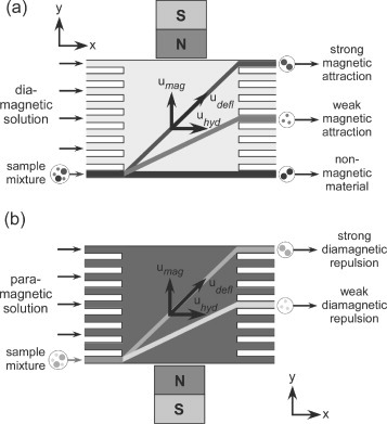
Magnetism can also be applied to the handling of ‘non-magnetic’, or more specifically diamagnetic, particles, such as polymer microparticles or biological cells. Diamagnetic materials experience a repulsive force from magnetic fields, although the effect is generally too weak to be noticed. However, the application of high magnetic fields, such as those that can be provided by superconducting magnets, can allow this phenomenon to be observed, and the repulsive effect has been used for the levitation against gravity of various larger diamagnetic objects including graphite [Citation22], organic substances [Citation22] and even frogs [Citation23].
The effect of diamagnetic repulsion can be enhanced by suspending the diamagnetic material in a paramagnetic medium such as pressurised oxygen for the levitation of water [Citation24] and biological substances [Citation25] or in an aqueous solution containing Mn (II) for the levitation of gold particles [Citation26]. Patterning of cells and particles suspended in aqueous paramagnetic solutions was also demonstrated. The particle suspension was placed atop a modulating magnetic field generated by a block with alternating strips of iron and aluminium in the field of an electromagnet [Citation27, Citation28]. Upon the application of a magnetic field the particles or cells migrated to form periodic lines as they were repelled from the areas of high magnetic field density.
The diamagnetic repulsion of materials has also been applied in smaller scale devices. Polystyrene particles and cells were trapped in a fused-silica capillary [Citation29, Citation30]. Permanent magnets were placed around the capillary and the particles or cells, suspended in a solution of manganese (II) chloride, were unable to enter the area of magnetic field, thus trapping them whilst the medium was continuously pumped through the capillary. Living cells have been trapped in paramagnetic gadolinium (III) salt solutions, where a suspension was positioned between two permanent magnets such that cells were trapped in an area of low field and could be manipulated by simply moving the magnets [Citation31]. A continuous separation has been achieved in a flow device whereby polymer particles were levitated against gravity into different flow streams depending on their density, with the denser particles exiting via a lower outlet those that were less dense [Citation32].
Here, we explore the potential for an on-chip continuous flow separation system based on diamagnetic repulsion, for the separation of polymer particles of different sizes (figure (b)). The behaviour of 5 and 10 μm diameter polystyrene particles was investigated in solutions of aqueous 6 and 10% manganese (II) chloride to determine how these parameters affect the extent of repulsion experienced by the particles in a superconducting magnet.
Theory
The principle of our microfluidic diamagnetic repulsion system is illustrated in figure (b). Laminar flow streams of paramagnetic solution are generated in the x-direction across a rectangular separation chamber. Particles are introduced into the chamber and are deflected from the direction of laminar flow by an external magnetic field that repels the particles in the y-direction. The magnetic force, Fmag in N, on a particle, as shown in (Equation11 ), depends on the difference between the magnetic susceptibility of the particle, χp, and the magnetic susceptibility of the surrounding medium, χm, the volume of the particle, Vp in m3, the magnetic flux density of the applied field, B in T, the gradient of the magnetic field in the y-direction, dB/dy in T/m, as well as the permeability of free space, μ0=4×10⁻⁷ H m−1.
1 If the particle is ferro- or paramagnetic (χp>0) and the medium is diamagnetic (χm<0), the difference between the two becomes positive, resulting in a positive value of Fmag that signifies the attraction of the particle to the magnetic field. On the other hand, if the particle is diamagnetic (χp<0) and the medium is paramagnetic (χm>0) then the difference becomes negative, and therefore Fmag becomes negative which indicates that the particle is repelled from the field. Therefore, if the magnetic flux density, the gradient of the field and the magnetic susceptibility of the particle are kept constant, the force on the particle depends only on the magnetic susceptibility of the medium and the particle size.
Whilst being deflected through the paramagnetic medium (figure (b)), the particle also experiences a viscous drag force, Fvis in N, as shown in (Equation22 ) [Citation33].
2 where η is the liquid viscosity in kg (m s)−1, r is the radius of a particle in m, umag is the velocity of the particle induced by the magnetic field in m s−1, and CW is the viscous drag coefficient due to the surface of the top and bottom chamber walls as described in (Equation3
3 ) [Citation33, Citation34].
3 where hz is the distance halfway between the top and bottom plates, in m. Hence umag can be determined by balancing the magnetic (Equation1
1 ) and viscous (Equation2
2 ) forces to give (Equation4
4 ).
4 When traversing the separation chamber, particles have a velocity in the x-direction due to the hydrodynamic flow applied by the external pump, uhyd in m s−1, and also a velocity in the y-direction, umag, due to the diamagnetic repulsion from the field. The sum of these two vectors results in the deflection of the particle through the chamber with a deflection velocity, udefl in m s−1, given by (Equation4
4 ).
5 Therefore, when uhyd is fixed, the extent of deflection of the particle depends entirely on umag. In turn, when the magnetic field and the magnetic susceptibility of the particles are kept constant, the value of umag depends only on the particle size, and the magnetic susceptibility and viscosity of the surrounding medium. Hence, initial investigations into the deflection of particles towards developing a separation system involved varying the size of diamagnetic polystyrene particles, and the magnetic susceptibility and viscosity of the paramagnetic manganese (II) chloride solution to determine their effect on umag.
Experimental details
Preparation of solutions
Paramagnetic solutions of 6% (0.48 mol L−1, χm=8.12×10⁻⁵, η=1.20×10⁻³ kg (m s)−1 at 20 °C) and 10% (0.79 mol L−1, χm=1.46×10⁻⁴, η=1.38×10⁻³ kg (m s)−1 at 20 °C) manganese (II) chloride were prepared by dissolving manganese (II) chloride tetrahydrate (Wako Pure Chemicals Industries, Tsukuba, Ibaraki, Japan) in deionised water. Sodium dodecyl sulphate (Wako Pure Chemicals) was added to a final concentration of 0.01% (w/v), in order to prevent sticking of the particles to each other and to the chip surface.
Preparation of polystyrene particle solutions
Diamagnetic polystyrene particles (χp=−8.21×10⁻⁶) of 5 μm diameter (Microbead NIST Traceable Size Standard) and 10 μm diameter (Megabead NIST Traceable Size Standard) were obtained as aqueous suspensions from Polysciences Europe GmbH (Eppenheim, Germany), with concentrations of 1.21×10⁸ and 1.87×10⁷ particles m L−1, respectively. Dilutions were performed separately for each particle size, with each being diluted 5 in 1000 times in 6 and 10% MnCl2 solutions, yielding final concentrations of 605 000 particles m L−1 and 93 500 particles m L−1 for the 5 and 10 μm diameter particles, respectively.
Microfluidic chip fabrication and setup
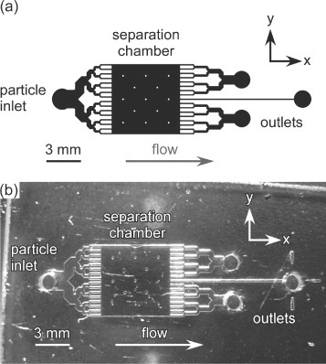
The microfluidic chip design featured a 6 mm×6 mm separation chamber, supported by 13 square posts that were each 200 μm×200 μm (figure ). 16 inlet channels facilitated the introduction of particle suspensions, and these were situated opposite 17 outlet channels, with each channel being of 100 μm width. The inlet channels were branched to maintain laminar flow over the chamber width, and to allow the particle suspension to disperse evenly throughout the chamber. Three outlets were featured but these held no relevance for this series of experiments.
Figure 2 (a) CAD schematic of the microfluidic chip design, featuring a 6 mm×6 mm chamber, 16 particle inlet channels and 17 outlet channels. (b) Photograph of the microfluidic device fabricated in glass.
The design as shown in figure (a) was patterned onto a 1.5 mm thick glass wafer coated with chromium and photoresist layers (Soda-lime glass, Nanofilm, Westlake Village, CA, USA) using a direct write laser lithography system (DWL, Heidelberg Instruments, Heidelberg, Germany) [Citation19]. After photodevelopment and chrome-etching the glass was wet etched with a solution of hydrofluoric acid to a depth of 20 μm (figure (b)). Access holes were drilled into the etched plate, which was subsequently pressure-bonded to a soda-lime glass cover plate [Citation35]. Short pieces of Teflon tubing (0.3 mm i.d., 1.58 mm o.d., Supelco, Bellefonte, PA, USA) were glued into the access holes. The tubing in the inlet hole was interfaced to a syringe pump (Pump 11 Plus, Harvard Apparatus, Kent, UK) via a short piece of fused-silica capillary (150 μm i.d., 360 μm o.d., Polymicro, Composite Metal Services, Shipley, UK) and a 3 m long polyethylether ketone (PEEK) tube (0.5 mm i.d., 1.6 mm o.d., Cole-Parmer, Hanwell, London, UK). The syringe pump held a 5 ml syringe (HSW, Poulten-Graf, London, UK) containing the appropriate solution or suspension. The tubing in the outlet holes was connected to a waste bottle via fused silica capillaries and Tygon tubing (1 mm i.d., 1.8 mm o.d., Cole-Parmer).
Experimental setup and procedure
The chip was placed atop a prism. A light emitting diode (LED, K40CWB-05, HOTHINK, Japan) was fixed over the chip to provide illumination. These were attached to an aluminium rail (DryLin W, Igus Inc., Tokyo, Japan) and a CCD camera (MN43H, with a T416MB lens, Elmo Company Ltd., Aichi, Japan) set beside the prism, such that the light from the LED passed through the separation chamber and was reflected by the prism into the CCD, allowing visualization of the particles inside the chamber (figure (a)). The CCD camera was interfaced to a DVD video recorder (DMR-E100H, Panasonic, Tokyo, Japan) to allow the deflection of the particles to be recorded. These recordings were later analysed with ImageJ freeware (http://rsb.info.nih.gov.ij/) to calculate the distance travelled by each particle in the y-direction over a given time, and thus the value of umag.
Figure 3 (a) Apparatus for visualisation of the chamber. Light from the LED passed through the chip and was reflected by the prism into the CCD camera. (b) The apparatus was inserted into the bore of a superconducting magnet.
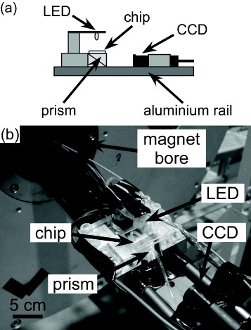
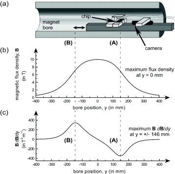
The rail was inserted into the bore (100 mm diameter) of a superconducting magnet (Jastec, Tokyo, Japan) such that the position of the chip could be changed by sliding the rail to the desired location in the bore (figure ). The maximum magnetic flux density of the superconducting magnet was maintained at 10 T. The chip was alternated between two positions in the bore, designated (A) and (B), which were 146 mm from the centre of the bore (y=0 mm) on each side. The value of B (dB/dy) was largest (±347 T2 m−1) at these positions and hence the greatest degree of particle repulsion was expected at these positions (see equation (Equation11 )).
Figure 4 (a) Schematic of the magnet bore illustrating how the chip was shifted between positions (A) and (B), (b) the magnetic flux density over the length of the bore, and (c) the product of the magnetic flux density and its gradient over the length of the bore, which was greatest at y=±146 mm from the centre of the bore, y=0.
Before experiments, the chip was flushed consecutively with water, ethanol, water and manganese (II) chloride solution. Particle suspension was then pumped through the chip at an applied flow rate of 400 μl h−1, and the apparatus inserted into the bore.
Results and discussion
The on-chip repulsion of diamagnetic polystyrene particles was investigated in paramagnetic aqueous manganese (II) chloride solution to examine its potential for on-chip free-flow separations. The deflection behaviour of 5 and 10 μm diameter particles was observed in 6 and 10% MnCl2 solutions at positions (A) and (B) in the superconducting magnet bore. The magnetically induced velocity, umag, was determined as described in the experimental section and the results are summarized in table , together with the theoretical values of umag as calculated using equation (Equation44 ). Twelve particles were analysed in each case unless otherwise stated. Results are not shown for the 5 μm particles in 10% MnCl2 at position (B) due to the particle throughput being too low at the time.
Table 1 The theoretical and experimental values of the magnetically induced velocities of the polystyrene particles and the magnetic force acting on them in the magnet bore.
The results show a greater repulsion of the 10 μm diameter particles in comparison to the 5 μm diameter particles when the manganese solution concentration was kept constant. This was expected from equations (Equation11 ) and (Equation4
4 ) as a larger particle volume (Vp) leads to an increase in Fmag and therefore in umag. The increase in deflection between the particle sizes was more obvious in the 10% MnCl2 solution than in the 6% MnCl2 solution due to the larger difference between magnetic susceptibilities of the particles and medium (χp–χm). In the case of the 10% MnCl2, the value of umag almost doubled when using the 10 μm rather than the 5 μm particles. Comparatively, suspending the particles in 6% MnCl2 solution showed an increase in umag of only 1.3 times when using the 10 μm instead of the 5 μm particles. It is interesting to note that, although umag should be the same at both positions (A) and (B) for each combination of MnCl2 concentration and particle size, the experimental values differ somewhat. This may be due to the chip being slightly out of position in the bore, a problem that could be solved by employing a more sophisticated system of moving the rail to and fro between positions (A) and (B).
The theoretical and experimental results match well, and although in some cases the experimental umag and Fmag results are higher than the theoretical values, the expected values are all within the experimental error range. The slight differences may be partially attributed to an uncertainty in the viscosity of the paramagnetic solution, since the temperature of the system was not controlled throughout the experiments, and possibly due to the assumptions made concerning the movement of the particles through midpoint between the top and bottom glass plate and the drag that they add to the particles' path.
As an initial investigation, these results clearly show that larger particles are deflected to a greater extent than smaller particles in a high magnetic field, and that this effect can be enhanced by increasing the concentration of MnCl2 and thus increasing the difference between magnetic susceptibility of the particle and medium. This is illustrated in figure , where the trajectories of the particles are shown for each set of parameters, based on the average particle velocities in table .
Figure 5 Particle paths through the microfluidic chamber at (a) position (A), and (b) position (B) in the superconducting magnet. The numbered paths correspond to particle trajectories for each set of parameters, where (1) is 10 μm particles in 10% MnCl2, (2) 10 μm particles in 6% MnCl2, (3) 5 μm particles in 6% MnCl2, and (4) 5 μm particles in 10% MnCl2. The particle trajectories were determined from the average experimental velocities calculated in table .

By rearranging equation (Equation44 ), the theoretical lower limits of the system were calculated. The lowest concentration of manganese chloride required to deflect a 10 μm particle as far as one outlet from its original path was estimated to be 1%, while for the 5 μm particles it was estimated to be around 3–4%. A dramatic reduction in manganese concentration, without the addition of additives, would also reduce the density of the medium, causing the particles to sink and potentially contact the lower surface of the chamber. Therefore, a concentration of 6% MnCl2 is the recommended lower limit to avoid such problems of particles settling. At both the 6 and 10% MnCl2 concentrations, the lowest particle diameter that could be deflected as far as one outlet was calculated to be 4 μm. However, optimisation of the magnetic field so as to generate a higher value of B (dB/dy) would reduce the limits of manganese concentration and particle size further. The upper limit of the particle size was limited by the depth of the chip, with particle diameters much larger than 10 μm introducing a risk of blockages, although the depth could be increased, thus allowing for larger particles to be analysed.
Conclusions
The deflection behaviours of 5 and 10 μm diamagnetic polystyrene particles in 6 and 10% aqueous solutions of paramagnetic manganese (II) chloride were observed in the high magnetic field of a superconducting magnet. The 10 μm particles experienced a greater repulsive force from the magnetic field than the smaller 5 μm particles, and this effect was enhanced by increasing the manganese (II) chloride solution concentration from 6 to 10%. These initial results demonstrate the potential of the method for on-chip continuous flow separations of diamagnetic materials based on their size. This preliminary study paves the way for the development of a system capable of separating different types of diamagnetic materials including biological specimens such as cells without the requirement of sample labelling.
References
- WhitesidesG M 2006 Nature 442 368 http://dx.doi.org/10.1038/nature05058
- ManzAGraberNWidmerH M 1990 Sens. Actuators B 1 244 http://dx.doi.org/10.1016/0925-4005(90)80209-I
- ReyesD RIossifidisDAurouxP AManzA 2002 Anal. Chem. 74 2623 http://dx.doi.org/10.1021/ac0202435
- AurouxP AIossifidisDReyesD RManzA 2002 Anal. Chem. 74 2637 http://dx.doi.org/10.1021/ac020239t
- VilknerTJanasekDManzA 2004 Anal. Chem. 76 3373 http://dx.doi.org/10.1021/ac040063q
- DittrichP STachikawaKManzA 2006 Anal. Chem. 78 3887 http://dx.doi.org/10.1021/ac0605602
- WestJBeckerMTombrinkSManzA 2008 Anal. Chem. 80 4403 http://dx.doi.org/10.1021/ac800680j
- de MelloA 2002 Lab. Chip 2 48N http://dx.doi.org/10.1039/b207266c
- PammeN 2007 Lab. Chip 7 1644 http://dx.doi.org/10.1039/b712784g
- Kersaudy-KerhoasMDhariwalRDesmulliezM P Y 2008 IET Nanobiotechnol. 2 1 http://dx.doi.org/10.1049/iet-nbt:20070025
- KawaguchiH 2000 Prog. Polym. Sci. 25 1171 http://dx.doi.org/10.1016/S0079-6700(00)00024-1
- VerpoorteE 2003 Lab. Chip 3 60N http://dx.doi.org/10.1039/b313217j
- PammeN 2006 Lab. Chip 6 24 http://dx.doi.org/10.1039/b513005k
- YamadaMNakashimaMSekiM 2004 Anal. Chem. 76 5465 http://dx.doi.org/10.1021/ac049863r
- YamadaMSekiM 2005 Lab. Chip 5 1233 http://dx.doi.org/10.1039/b509386d
- YamadaMSekiM 2006 Anal. Chem. 78 1357 http://dx.doi.org/10.1021/ac0520083
- ChoiSParkJ K 2005 Lab. Chip 5 1161 http://dx.doi.org/10.1039/b505088j
- PeterssonFAbergLSward-NilssonA MLaurellT 2007 Anal. Chem. 79 5117 http://dx.doi.org/10.1021/ac070444e
- PammeNManzA 2004 Anal. Chem. 76 7250 http://dx.doi.org/10.1021/ac049183o
- PammeNEijkelJ C TManzA 2006 J. Magn. Magn. Mater. 307 237 http://dx.doi.org/10.1016/j.jmmm.2006.04.008
- PammeNWilhelmC 2006 Lab. Chip 6 974 http://dx.doi.org/10.1039/b604542a
- BeaugnonETournierR 1991 Nature 349 470 http://dx.doi.org/10.1038/349470a0
- BerryM VGeimA K 1997 Eur. J. Phys. 18 307 http://dx.doi.org/10.1088/0143-0807/18/4/012
- IkezoeYHirotaNNakagawaJKitazawaK 1998 Nature 393 749 http://dx.doi.org/10.1038/31619
- HirotaNKurashigeMIwasakaMIkehataMUetakeHTakayamaTNakamuraHIkezoeYUenoSKitazawaK 2004 Physica B 346 267 http://dx.doi.org/10.1016/j.physb.2004.01.063
- TakayamaTIkezoeYUetakeHHirotaNKitazawaK 2005 Appl. Phys. Lett. 86 http://dx.doi.org/10.1063/1.1947371
- KimuraTYamatoMNaraA 2004 Langmuir 20 572 http://dx.doi.org/10.1021/la035768m
- KimuraTSatoYKimuraFIwasakaMUenoS 2005 Langmuir 21 830 http://dx.doi.org/10.1021/la047517z
- WataraiHNambaM 2001 Anal. Sci. 17 1233 http://dx.doi.org/10.2116/analsci.17.1233
- WataraiHNambaM 2002 J. Chromatogr. A 961 3 http://dx.doi.org/10.1016/S0021-9673(02)00748-3
- WinklemanAGudiksenK LRyanDWhitesidesG MGreenfieldDPrentissM 2004 Appl. Phys. Lett. 85 2411 http://dx.doi.org/10.1063/1.1794372
- WinklemanAPerez-CastillejosRGudiksenK LPhillipsS TPrentissMWhitesidesG M 2007 Anal. Chem. 79 6542 http://dx.doi.org/10.1021/ac070500b
- IiguniYSuwaMWataraiH 2004 J. Chromatogr. A 1032 165 http://dx.doi.org/10.1016/j.chroma.2003.10.134
- HappelJBrennerH 1973 Low Reynolds Number Hydrodynamics 2nd revised edn Leyden Noordhoff International Publishing
- IlesAOkiAPammeN 2007 Microfluid Nanofluid 3 119 http://dx.doi.org/10.1007/s10404-006-0101-z