Abstract
Fretting fatigue behaviour of Ni-free high-nitrogen steel (HNS) with a yield strength of about 800 MPa, which was prepared by nitrogen gas pressurized electroslag remelting, was studied in air and in phosphate-buffered saline (PBS(-)). For comparison, fretting fatigue behaviour of cold-rolled SUS316L steel (SUS316L(CR)) with similar yield strength was examined. The plain fatigue limit of HNS was slightly lower than that of SUS316L(CR) although the former had a higher tensile strength than the latter. The fretting fatigue limit of HNS was higher than that of SUS316L(CR) both in air and in PBS(-). A decrease in fatigue limit of HNS by fretting was significantly smaller than that of SUS316L(CR) in both environments, indicating that HNS has better fretting fatigue resistance than SUS316L(CR). The decrease in fatigue limit by fretting is discussed taking into account the effect of friction stress due to fretting and the additional influences of wear, tribocorrosion and plastic deformation in the fretted area.
1. Introduction
Nitrogen (N) greatly decreases a martensite start temperature and stabilizes an austenite phase in steel [Citation1]. It also provides solution strengthening and strengthening of grain boundaries in steel. Thus, N is expected to replace nickel (Ni) as an austenite stabilizer and to promote savings of a rare metal and recycling. Ni-free high-nitrogen austenitic stainless steel (henceforth called HNS) has been reported to have excellent mechanical properties and corrosion resistance compared to conventional austenitic stainless steels [Citation2, Citation3].
At present, industrially pure titanium, titanium alloys such as Ti–6Al–4V(ELI), Co–Cr alloys and austenitic stainless steels such as SUS316L steel are used as metallic biomaterials. In particular, SUS316L steel is used for structural bio-devices because it has good workability, high strength and high toughness and also because it is less expensive than the other materials. However, SUS316L steel contains a large amount of Ni, which has been reported to be highly toxic for living bodies [Citation4]. Therefore, HNS is being studied for structural bio-devices [Citation5]. Many investigations on mechanical properties and corrosion resistance of HNS have been reported [Citation5–Citation11].
The environment in a living body is severely corrosive to metallic materials. On top of that, many of the components are used under mechanical load. In particular, artificial hip joints, etc are loaded repeatedly during walking. Thus, metallic biomaterials are required to have not only excellent corrosion resistance but also excellent corrosion fatigue properties. Furthermore, fretting damage occurs when two components in contact with each other are loaded repeatedly, for instance, in the case of a bone plate and a screw used for fracture treatment. Fretting causes continuous removal of surface oxide films, so that the fretting in a corrosive environment enhances corrosion damage and corrosion enhances fretting wear. The synergistic phenomenon is called tribocorrosion. The tribocorrosion generally promotes the fatigue damage of the materials. As well as the friction stress added to the cyclic axial stress, surface tribocorrosion damage is one of the reasons why corrosion fatigue strength accompanied by fretting (fretting corrosion fatigue strength) is generally lower than conventional corrosion fatigue strength [Citation12].
Stems of artificial hip joints and bone plates have been reported to fracture through fretting corrosion fatigue [Citation12]. Therefore, it is important to understand fretting corrosion fatigue properties in order to evaluate the reliability of metallic biomaterials. The fretting fatigue behaviour of metallic biomaterials in simulated body fluids has been reported for industrial pure titanium, titanium alloys, Co–Cr alloys and SUS316L steel [Citation13–Citation15]. However, no report on the fretting fatigue behaviour of HNS has been published, although fatigue behaviour in a simulated body fluid has been reported [Citation16].
In this work, fretting fatigue behaviour of HNS was studied in air and in a simulated body fluid. For comparison, fretting fatigue behaviour of cold-rolled commercially available SUS316L steel was also studied. Furthermore, the effects of wear, tribocorrosion and plastic deformation in the fretted area on fretting fatigue behaviour were discussed.
2. Materials and methods
2.1. Materials
Ni-free HNS was prepared using a nitrogen gas pressurized electroslag remelting process. A 20 kg ingot of HNS was reduced to bars with a cross section of 15 × 15 mm2 by hot forging and rolling after heating at 1473 K and then each bar was solution treated for 1.8 ks at 1503 K. For comparison, commercial SUS316L steel bars with a diameter of 25 mm, which satisfied JIS (Japanese Industrial Standards) G4303, were cold rolled by 20% in cross section to obtain a yield strength similar to that of HNS. Tables and show the chemical compositions and mechanical properties of the steels used, respectively.
Table 1. Chemical compositions of HNS and SUS316L steel (mass%).
Table 2. Mechanical properties of HNS and SUS316L(CR).
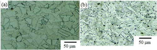
Young's modulus was measured using strain gauges adhered to the parallel parts of a tensile specimen. HNS contained 0.04 mass% of Ni as impurity and 1.05 mass% of N. The tensile strengths of the HNS and the cold-rolled SUS316L steel (henceforth called SUS316L(CR)) were about 1200 and 880 MPa, respectively, although the yield strength of both steels was about 800 MPa. Figures (a) and (b) show the optical micrographs of the cross section of HNS and SUS316L(CR) bars, respectively. HNS had an austenite single-phase structure with a grain size of about 30 μm, and SUS316L(CR) consisted of austenite grains with a cold-rolled microstructure such as mechanical twins. X-ray diffraction analysis revealed that SUS316L(CR) included a slight amount of martensite, while HNS showed no slight diffraction peak from martensite.
Figure 1. Optical micrographs of HNS (a) and SUS316L(CR) (b).
2.2. Fretting fatigue tests
Figure shows the configurations of a fretting fatigue specimen and a fretting pad and figure shows the schematic diagram of a fretting fatigue test. The specimen had a pair of parallel flat surfaces for attaching the fretting pads. A couple of pads were fixed to both specimen surfaces using the pushing rods and pressed by a hydraulic actuator. The jig for the pushing rods and pads was not rigidly fixed on the fatigue apparatus and the position of the fretting pads was not constrained. Therefore, the position of the pads could shift along with the elongation of the specimen, which enabled the equal relative displacement between the two fretting pad ends and the specimen surface in the opposite directions. The fatigue specimens, fretting pads and pushing rods were machined from the same steel. Using #600 emery paper, the surface of the specimen and the contact surface of the pad were ground parallel to the direction of cyclic loading and then cleaned with acetone. A phosphate-buffered saline (PBS(-)) solution of pH 7.5, which was prepared from 8 g of NaCl, 0.2 g of KCl, 1.15 g of Na2HPO4 and 0.2 g of KH2PO4 in 1 l of ultrapure water, was used as a simulated body fluid. The fluid was kept at 310 ± 1 K and aerated with a 4% O2-containing N2 gas (4% O2/N2 gas) at a flow rate of 20 cm3 min−1 during fatigue testing. The aeration resulted in about 1.2 ppm of dissolved oxygen content in PBS(-).
Figure 2. Configuration of a fretting fatigue specimen (a) and a fretting pad (b).
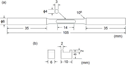
Figure 3. Schematic diagram of the fretting fatigue test in PBS(-).
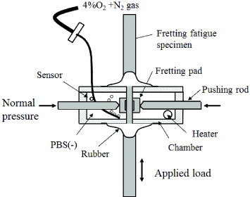
Fatigue tests were conducted using an electrohydraulic servo testing machine with a capacity of 25 kN (MTS 858 Mini Biomix). The stress waveform was sinusoidal, and the stress ratio (R = minimum stress/maximum stress) was 0.1 under axial tensile loading. The stress frequency was 20 Hz in air and 2 Hz in PBS(-) because frequencies in the range from 2 to 20 Hz hardly affected fatigue strength in air [Citation17]. The contact pressure of the fretting pads on the specimen surface was 30 MPa. The friction coefficient between the specimen surface and the pad was measured by attaching a strain gauge to the inner surface of the pad.
Since the Young's modulus of HNS is higher by 18% than that of SUS316L(CR), the relative displacement amplitude of HNS is smaller by 18% than that of SUS316L(CR) under the same stress amplitude according to the equation 1 where Samp is relative displacement amplitude, l is span of the fretting pad, σamp is stress amplitude and E is Young's modulus.
2.3. Polarization tests
Anodic polarization tests were conducted for HNS, SUS316L(CR) and as-received commercial SUS316L steel [Citation18] in the PBS(-) aerated with 4% O2/N2 gas. The temperature of the solution was maintained at 310 K. Discs with a diameter of 25 mm and a thickness of 2 mm were used as a specimen. The exposed area of the disc to the test solution was 1 cm2. A saturated calomel electrode (SCE) and a Pt plate were used as a reference and a counter electrode, respectively. The specimen was initially polarized at −0.7 V (versus SCE) for 10 min, followed by monitoring of open-circuit potential for 10 min, and then the potential of the specimen was swept to the anodic direction at a rate of 20 mV min−1.
3. Results
3.1. Fatigue and fretting fatigue tests
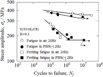
The relationships between stress amplitude (σa) and number of cycles to failure (Nf) (S–N relationships) for plain fatigue and fretting fatigue in air and PBS(-) are shown in figures and for HNS and SUS316L(CR), respectively. One data point was taken from one specimen. The plain fatigue strength of HNS in air was similar to that in PBS(-), and the plain fatigue strength at 107 cycles (fatigue limit) was about 320 MPa in both environments. The fretting fatigue strength of HNS was lower than the plain fatigue strength in both environments and the fretting fatigue strength at 107 cycles (fretting fatigue limit) in air was about 280 MPa, whereas that in PBS(-) was about 240 MPa. In the case of SUS316L(CR), the plain fatigue strength in air was slightly higher than that in PBS(-), and the plain fatigue limit was about 350 MPa in air and about 320 MPa in PBS(-). The fretting fatigue strength of SUS316L(CR) was no different in air than in PBS(-), and the fretting fatigue limit was about 180 MPa, which was approximately half as high as the fatigue limit. The fretting fatigue limit of HNS was obviously higher than that of SUS316L(CR) in both environments, although the plain fatigue limit of the former was lower than that of the latter. Moreover, the number of cycles to failure (fretting fatigue life) of HNS was larger than that of SUS316L(CR) under certain stress amplitudes providing the equal relative displacement for HNS and SUS316L(CR), for example under 240 and 200 MPa, respectively. It was revealed that HNS has noticeably better fretting fatigue properties than SUS316L(CR) in both environments.
Figure 4. Stress amplitude–number of cycles to failure (S–N) relationship of HNS.
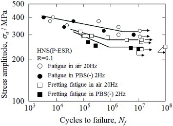
Figure 5. Stress amplitude–number of cycles to failure (S–N) relationship of SUS316L(CR).
3.2. Friction stress amplitude
Figure shows the relationships between applied stress amplitude and friction coefficient of HNS and SUS316L(CR) in air and PBS(-). The friction coefficient was obtained under the same conditions of the fretting fatigue tests. The friction coefficient μ is defined by the relation 2 where p is the contact pressure of the fretting pad and fa is the amplitude of friction force per unit area between the pad and the specimen surface. The friction coefficient varied slightly with the number of stress cycles. Thus, the data shown here were obtained at stress cycles of more than 3 × 10³, beyond which the friction coefficient became almost constant.
Figure 6. Stress amplitude dependence of friction coefficient.
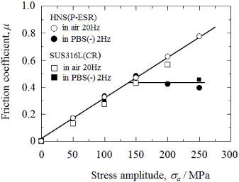
In this experiment, the friction coefficients in air were almost the same for both steels and increased linearly with applied stress amplitude. The friction coefficients of both steels in PBS(-) were also almost the same. Their friction coefficients were independent of applied stress amplitude and about 0.45 in a high-stress amplitude region, although they increased linearly with applied stress amplitude in a low-stress amplitude region. The almost constant friction coefficient in the high-stress amplitude region means that a gross slip occurred between the specimen surface and the pad, and that the friction coefficient was the dynamic friction coefficient.
3.3. Profiles of the fretted areas
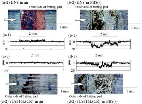
The cross-section profiles and their corresponding optical micrographs of the fretted areas of the HNS specimens tested up to about 107 cycles in air and in PBS(-) are shown in figures (a) and (b), respectively. The cross-section profiles and their corresponding optical micrographs of SUS316L(CR) are also shown in figures (c) and (d). In air, no noticeable wear loss occurred on both steels because no significant difference in the profile was observed between the fretted and the non-fretted areas of both steels. In contrast, the wear loss and the formation of a rough surface in PBS(-) were obvious in spite of the fact that the friction coefficient of the steels in PBS(-) is lower than that in air, as can be seen in figure . The obvious wear loss in PBS(-) is considered to be because fretting wear and corrosion synergistically enhanced the surface degradation (tribocorrosion).
Figure 7. Cross-sectional profiles and the corresponding optical micrographs of the fretted surface of HNS (a), (b) and SUS316L(CR) (c), (d). (a) In air, σa = 265 MPa, Nf = 1.32 × 10⁷; (b) in PBS(-), σa = 235 MPa, Nf = 1.07 × 10⁷; (c) in air, σa = 177 MPa, Nf = 1.20 × 10⁷; (d) in PBS(-), σa = 193 MPa, Nf = 1.30 × 10⁷. Arrows in the optical micrographs indicate the profile measurement direction.
3.4. Two-stage fatigue tests
As has been shown in figures and , the fretting fatigue strength is lower than the plain fatigue strength both in air and in PBS(-), indicating that a fretting fatigue crack initiates and grows even at a stress amplitude below the plain fatigue limit. The number of stress cycles needed to initiate a fatigue crack at a stress amplitude below the plain fatigue limit was determined using a two-stage fatigue test. In the two-stage test, a fretting fatigue test up to a certain number of stress cycles (Nff) at a given stress amplitude was followed by an additional plain fatigue test to failure using the same stress amplitude. The number of plain fatigue cycles of the second stage is represented as Npf.
Figures and show the relationship between Nff and the total stress cycles to failure (Ntf = Nff + Npf) at a stress amplitude of 294 MPa for HNS and 245 MPa for SUS316L(CR), respectively. These stress amplitudes were below their plain fatigue limit, and are those at which the fretting fatigue life of both steels was about 105 cycles. Since the 294 MPa for HNS was higher by 20% than 245 MPa for SUS316L(CR), the relative displacement between the fretting pad and the specimen surface for both steels was calculated to be almost equal according to equation (Equation11 ). When Nff is in a low-cycle region, no specimen fails even when Ntf is 107. When Nff of HNS reaches a critical value, 1.3 × 10⁵ and 7 × 10⁴ cycles in air and in PBS(-), respectively, Ntf decreases drastically and becomes close to the fretting fatigue life. This fact indicates that a certain cycle number of the initial fretting, Nff, is required to initiate the critical fretting damage, such as microcracks, which can be propagated by plain fatigue at a stress amplitude lower than the plain fatigue limit. The critical fretting cycles for the drastic decrease in the total life cycles is defined as crack initiation life.
Figure 8. Effect of the initial fretting fatigue test on total life cycles for HNS.
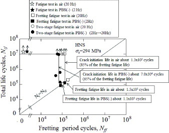
Figure 9. Effect of the initial fretting fatigue test on total life cycles for SUS316L(CR).
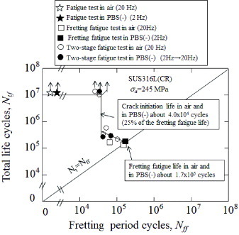
The crack initiation life of HNS is about 85 and 65% of the fretting fatigue life in air and in PBS(-), respectively. Thus, the fretting fatigue life of HNS is governed mainly by the crack initiation life at the stress amplitude of 294 MPa, and the crack initiation life of HNS in PBS(-) is shorter than that in air. It can, therefore, be considered that the tribocorrosion taking place under the fretting condition in PBS(-) accelerates the crack initiation. On the other hand, the crack initiation life of SUS316L(CR) at a stress amplitude of 245 MPa is about 25% of the fretting fatigue life in both environments. The crack propagation life occupies a large part of the fretting fatigue life of SUS316L(CR) and the crack propagation life of SUS316L(CR), 1.3 × 10⁵ cycles in both environments, is obviously longer than that of HNS. The ratios of crack initiation and propagation lives to the fretting fatigue life measured in the two-stage fatigue tests indicate that the crack-initiation resistance of HNS is higher than that of SUS316L(CR), whereas the crack-propagation resistance of HNS is relatively lower than that of SUS316L(CR).
3.5. Polarization test
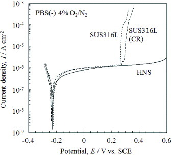
Anodic polarization curves of HNS, SUS316L(CR) and as-received SUS316L [Citation18] in PBS(-) are shown in figure . The corrosion potentials and passive current densities of the three steels were approximately equal, respectively. The curves of SUS316L(CR) and as-received SUS316L showed an abrupt increase in current density around 0.3 V versus SCE corresponding to pitting. The pitting potentials of both SUS316L steels were similar to each other. On the other hand, HNS showed no abrupt increase in current density, which indicates that HNS has excellent resistance to pitting corrosion.
Figure 10. Polarization curves for HNS, SUS316L(CR) and as-received SUS316L.
4. Discussion
In fretting fatigue tests under axial loading, the cyclic friction stress is induced between the specimen surface and the fretting pad, and that is added to the cyclic axial stress. The effective stress amplitude in the fretted area of the specimen, σft, is given by the equation [Citation19] 3 where σaf is cyclic axial tensile stress amplitude and fa is cyclic friction stress amplitude. When the axial tensile stress increases, positive friction stress increases and when axial stress decreases, negative friction stress increases. The friction stress amplitude, fa, is given by the equation
4 where p is the contact pressure of the fretting pad and μ is the friction coefficient at a given axial stress amplitude. From equations (Equation3
3 ) and (Equation4
4 ), the effective stress amplitude, σft, at the fretted area is given by
5
The additional friction stress amplitude is one of the reasons for the lower fretting fatigue limit than the plain fatigue limit. When the applied axial stress, σaf, is equal to the fretting fatigue limit, σff, the effective stress, σft, is expressed by 6 where μ∗ is the friction coefficient at a stress amplitude that is equal to the fretting fatigue limit. Assuming that the effect of fretting is only the addition of friction stress, 2μ∗p, to the applied axial stress and that the other effects of fretting such as the surface damage associated with wear and corrosion can be neglected, the effective stress σft should be the same as the plain fatigue limit, σpf, when fretting fatigue limit is applied. Thus, substituting σpf for σft in equation (Equation6
6 ),
7
If σff obtained by using equation (Equation77 ) is in agreement with the experimental data, the effects of fretting wear and corrosion damages can be neglected as assumed. Otherwise, those effects should be taken into account in addition to the effect of friction stress.
In order to estimate the additional effects, the experimentally measured fretting fatigue limit, σmff, is compared with the fretting fatigue limit, σff, calculated using equation (Equation77 ) based only on stress effects. Here, μ∗ and σpf are experimentally obtained and p is 30 MPa. Table shows σff and (σff–σmff) for HNS and SUS316L(CR). When (σff–σmff) is positive, fretting and corrosion damage on the specimen surface is considered to accelerate fretting fatigue.
Table 3. σff and (σff–σmff) for the fretting fatigue limit of HNS and SUS316L(CR).
The (σff–σmff) values in table were positive except for the value of HNS in air. The difference between σff and σmff revealed that not only friction stress but also the fretting and corrosion damage are affected the fretting (corrosion) fatigue behaviour. Both in air and in PBS(-), SUS316L(CR) had a greater |σff–σmff| than HNS, suggesting that the effect of fretting and corrosion damage on SUS316L(CR) is more remarkable than that on HNS.
Both HNS and SUS316L(CR) in air showed the formation of stick and slip regions in the fretted area and the fracture of the specimens at the boundary between the two regions. A representative appearance of fretted area of HNS fractured in air and a schematic drawing of a fretted specimen are shown in figures (a)–(c), respectively. A main crack is initiated at the boundary between the bright and dark areas of a backscattered electron microscope image, which corresponds to stick and slip regions, respectively (figure (b)). Nakazawa et al [Citation20] suggested that the fracture at the boundary between two regions is attributed to the stress concentration at the stick region in the case of high-strength steel and Ti–6Al–4V alloy. The stress concentration at the local parts of the fretted area is supposed to occur also on HNS and SUS316L(CR) owing to the difference in friction coefficient between the stick and slip regions. Thus, the local stress concentration around the crack initiation site can be one of the reasons for the obviously large value of (σff–σmff) of SUS316L(CR) in air but this is not applicable to the fretting fatigue behaviour of HNS in air.
Figure 11. Optical micrographs of the fracture surface and fretted area of HNS in air, σa = 275 MPa, Nf = 3.88 × 10⁶ (a), backscattered electron microscopy image of the fretted area near the crack initiation site of (a-2), (b), and schematic drawing of a fretted specimen (c).
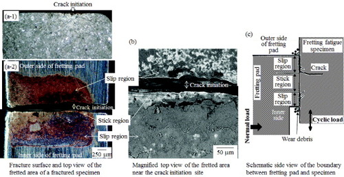
The existence of the stick region indicates adhesive fretting wear [Citation20]. The adhesive sliding of the fretting pad can cause plastic deformation associated with work hardening of the material surface. The surface strengthening by the work hardening can probably suppress crack initiation. Here, the work-hardening rates of HNS and SUS316L(CR) are estimated to be 1100 and 560 MPa, respectively, from the yield strength, tensile strength and elongation. The higher Vickers hardness of HNS than that of SUS316L(CR) (table ) also indicates the higher work-hardening rate of HNS. The higher work-hardening rate of HNS than that of SUS316L(CR) indicates that the plastic deformation zone of HNS has been strengthened more than that of SUS316L(CR). It also suggests that the plastic deformation zone of HNS was shallower than that of SUS316L(CR). The adhesive sliding might also induce martensitic transformation and precipitation of nitrides in the fretted area [Citation21, Citation22]. It has been reported that martensite in an austenitic stainless steel increased crack initiation resistance [Citation23]. Therefore, the phase transformation possibly enhances the surface strengthening, resulting in suppression of crack initiation as well as the work hardening.
The slightly negative value of (σff–σmff) of HNS in air can be then attributed to the suppression of the crack initiation with the surface strengthening. In the case of SUS316L(CR), the less surface strengthening of the deeper plastic deformation zone by the work hardening probably could not suppress the crack initiation.
In PBS(-), the (σff–σmff) values of HNS and SUS316L(CR) are 56 and 117 MPa, respectively (table ), and these values were larger than those in air indicating that the tribocorrosive environment in PBS(-) accelerates fretting fatigue. The rough surface in the wear trace of both steels in PBS(-) (figure ) suggests the local stress concentration in wear trace. In the case of HNS, the local stress concentration in wear trace could accelerate the crack initiation, so that the crack initiation life and fretting fatigue limit in PBS(-) became shorter and lower than those in air, respectively. On the other hand, the crack propagation life of HNS was not noticeably affected by the test environments (figure ) and HNS showed high pitting corrosion resistance in PBS(-) (figure ), indicating that the corrosion effect on the crack propagation rate of HNS in PBS(-) was not notable.
In the case of SUS316L(CR) in PBS(-), the fretting fatigue limit and crack initiation life in PBS(-) are the same as those in air (figures and ), respectively. In PBS(-), tribocorrosion and the local stress concentration in the wear trace could accelerate crack initiation. On the other hand, local stress concentration in the fretted area presumably accelerated the crack initiation in air. It is supposed that the crack initiation life of SUS316L(CR) in air and in PBS(-) became the same because the contributions of the effects in air and in PBS(-) were similar by chance. To understand the contributions of the effects on the fretting fatigue behaviour more quantitatively, further investigation is necessary.
Figure shows the relationship between the measured fretting fatigue limit, σmff, and the fretting fatigue limit, σff, calculated using equation (Equation77 ) for various metallic biomaterials tested in air with the same fretting fatigue method as that in this work [Citation13–Citation15]. σmff in air is almost the same as σff when σff is lower than 150 MPa, indicating that the lower fretting fatigue limit than the plain fatigue limit can be explained only by the effect of the friction stress amplitude in addition to the axial stress amplitude.
Figure 12. Relationship between the calculated fretting fatigue limit and the measured fatigue limit in air [Citation13–Citation15]. (The values of HNS and SUS316L(CR) were obtained in this experiment.)
![Figure 12. Relationship between the calculated fretting fatigue limit and the measured fatigue limit in air [Citation13–Citation15]. (The values of HNS and SUS316L(CR) were obtained in this experiment.)](/cms/asset/d6196df3-8df0-424d-a714-3bec6a0c99bc/tsta_a_11661362_f0012_oc.jpg)
σmff of Co–Cr alloy [Citation14] is slightly higher than σff in a similar way as HNS. Since remarkable wear was observed in the fretted area of Co–Cr, it was presumed that the wear suppresses the growth of micro-cracks to be a critical length [Citation14]. On the other hand, σmff of Ti–6Al–4V(STA: solution treated and aged) alloy is significantly lower than σff in a similar way as SUS316L(CR). Stick and slip regions were formed also on Ti–6Al–4V [Citation20]. The local stress concentration in the fretted area, as mentioned above, was then also suggested for Ti–6Al–4V [Citation20]. HNS has the highest fretting fatigue limit in air among the conventionally used materials given in the figure.
Figure shows a relationship in PBS(-) similar to that in figure [Citation13–Citation15]. The measured fretting fatigue limit, σmff, in PBS(-) is generally lower than σff. This result is interpreted in terms of the tribocorrosion and the associated surface roughening and the local stress concentration promoting the crack initiation. A large decrease of σmff from σff is observed particularly for Ti–6Al–4V(STA) and SUS316L(CR) in PBS(-) as well as in air.
Figure 13. Relationship between the calculated fretting fatigue limit and the measured fatigue limit in PBS(-) [Citation13–Citation15]. (The values of HNS and SUS316L(CR) were obtained in this experiment.)
![Figure 13. Relationship between the calculated fretting fatigue limit and the measured fatigue limit in PBS(-) [Citation13–Citation15]. (The values of HNS and SUS316L(CR) were obtained in this experiment.)](/cms/asset/595dc4be-888c-40db-9b3e-41bcc79a8029/tsta_a_11661362_f0013_oc.jpg)
As shown in figure , HNS has a remarkably high plain fatigue limit as well as SUS316L(CR). In addition, HNS has the highest fretting fatigue limit in PBS(-) among the conventionally used materials given in the figure and the fretting fatigue limit of HNS is obviously higher than that of SUS316L(CR). Furthermore, HNS exhibits higher pitting resistance than SUS316L(CR) and SUS316L as shown in figure . Consequently, it can be said that HNS is a promising material used as a biomaterial with resistance to fretting fatigue and corrosion.
5. Conclusions
Fretting fatigue behaviour was studied in air and in PBS(-) for Ni-free high-nitrogen steel (HNS) with a yield strength of about 800 MPa. For comparison, SUS316L(CR) with a similar yield strength was also studied. The results obtained are as follows.
| 1. | The plain fatigue limit of HNS was slightly lower than that of SUS316L(CR) both in air and in PBS(-), although the former steel has a higher tensile strength than the latter. | ||||
| 2. | The fretting fatigue limit of HNS was significantly higher than that of SUS316L(CR) both in air and in PBS(-) as a result of an obviously smaller decrease in fatigue limit of HNS by fretting than that of SUS316L(CR). | ||||
| 3. | The crack-initiation life of HNS was longer than that of SUS316L(CR) both in air and in PBS(-) under the fatigue stresses giving the same fatigue life. | ||||
| 4. | The corrosion potentials and passive current densities of both steels were approximately equal. The resistance of HNS to pitting is significantly higher than that of SUS316L(CR) and no pitting of HNS was observed up to oxygen evolution potential. | ||||
| 5. | HNS showed the highest fretting fatigue limit in air and in PBS(-) among the conventionally used metallic biomaterials such as SUS316L(CR), Ti–6Al–4V alloy and Co–Cr alloy. | ||||
Consequently, it can be said that HNS is a potential metallic biomaterial that has higher fretting fatigue strength and corrosion resistance than conventional materials.
Acknowledgments
We thank Dr Y Katada, NIMS, for a fruitful discussion. We thank S Iwasaki, S Kuroda, T Hibaru, K Nakazato and Y Taniuchi, NIMS, for preparation of Ni-free high-nitrogen austenitic steel. Also, we thank Ms A Imaizumi, NIMS, for preparation of the fatigue specimens. Part of this study was supported by a Grant-in-Aid for Scientific Research (B) (20360319) from the Japan Society for the Promotion of Science (JSPS) and World Premier International Research Centre Initiative (WPI) on Materials Nanoarchitectonics, MEXT, Japan.
References
- IrvineK JLlewellymD TPickeringF B 1961 J. Iron Steel Inst. 199 153
- SpeidelM OSpeidelH J 2006 Proc. Int. Conf. on High Nitrogen Steels Beijing Metallurgical Industry Press
- ImaiY 1994 Hagane no Bussei to Chisso Tokyo AGNE Gijutsu Center
- MenzelJKirschnerWSteinG 1996 ISIJ Int. 36 893 10.2355/isijinternational.36.893
- KurodaDHanawaTHibaruTKurodaSKobayashiM 2003 Mater. Trans. 44 1363 10.2320/matertrans.44.1363
- OsozawaKKobayashiH 2006Corrosion resistant property of nitrogen steels—especially in regard to stainless steelsProc. of Dai 190 Kai Nishiyama Kinen Gijyutsu Koza Tokyo The Iron and Steel Institute of Japan p 71
- SagaraMUnoHKatadaYKodamaT 2002 Tetsu to Hagane 88 672
- SagaraMKatadaYKodamaTTsuruT 2003 J. Japan Inst. Met. 67 67
- KatadaYSagaraMKobayashiYKodamaT 2004 Mater. Manuf. Process. 19 19 10.1081/AMP-120027495
- KurodaDHanawaTHibaruTKurodaSKobayashiMKobayashiT 2003 Mater. Trans. 44 414 10.2320/matertrans.44.414
- KurodaDHiromotoSHanawaTKatadaY 2002 Mater. Trans. 43 3100 10.2320/matertrans.43.3100
- MaruyamaN 2010Mechanical testing of metallic biomaterials Metals for Biomedical Devices NiinomiM Cambridge Woodhead p 157
- MaruyamaNKobayashiTSumitaM 1995 J. Japan. Soc. Biomater. 13 14
- MaruyamaNKobayashiTNakazawaKSumitaMSatoM 1999 J. Japan. Soc. Biomater. 17 172
- NakazawaKSumitaMMaruyamaN 1999 J. Japan Inst. Met. 63 1600
- MaruyamaNSanbeMKatadaYKanazawaK 2009 Mater. Trans. 50 2615 10.2320/matertrans.M2009216
- MaruyamaNNakazawaKSumitaMSatoM 2000 J. Japan. Soc. Biomater. 18 17
- MaruyamaNMoriDHiromotoSKanazawaKNakamuraM 2011 Corros. Sci. 53 2222 10.1016/j.corsci.2011.03.004
- NishiokaKHirakawaK 1968 Trans. Japan Soc. Mech. Eng. 34 1635 10.1299/kikai1938.34.1635
- NakazawaKSuitaMMaruyamaN 1992 Am. Soc.Test. Mater. 1159 115
- BernsHGavriljukV GNabiranNPetrovY NRiednerSTrophimovaL N 2010 Steel Res. Int. 81 299 10.1002/srin.200900142
- WeiXHuaMXueZGaoZLiJ 2009 Wear 267 1386 10.1016/j.wear.2008.12.068
- NakajimaMAkitaMUematsuYTokajiK 2007 Trans. Japan Soc. Mech. Eng. A 73 796 10.1299/kikaia.73.796