Abstract
In this study, a core/shell bi-layered calcium phosphate cement (CPC)-based composite scaffold with adjustable compressive strength, which mimicked the structure of natural cortical/cancellous bone, was fabricated. The dense tubular CPC shell was prepared by isostatic pressing CPC powder with a specially designed mould. A porous CPC core with unidirectional lamellar pore structure was fabricated inside the cavity of dense tubular CPC shell by unidirectional freeze casting, followed by infiltration of poly(lactic-co-glycolic acid) and immobilization of collagen. The compressive strength of bi-layered CPC-based composite scaffold can be controlled by varying thickness ratio of dense layer to porous layer. Compared to the scaffold without dense shell, the pore interconnection of bi-layered scaffold was not obviously compromised because of its high unidirectional interconnectivity but poor three dimensional interconnectivity. The in vitro results showed that the rat bone marrow stromal cells attached and proliferated well on the bi-layered CPC-based composite scaffold. This novel bi-layered CPC-based composite scaffold is promising for bone repair.
1. Introduction
Calcium phosphate cement (CPC) is considered as a promising bone substitute material for large bone defects caused by trauma or bone disease [Citation1]. CPC is composed of one or more calcium phosphates and a liquid phase, and the formed paste hardens at low temperature by entanglement of the crystals precipitated within the paste [Citation2, Citation3]. CPC is biodegradable, and has excellent biocompatibility and osteoconductivity because its hydration product is poorly crystalline hydroxyapatite (HA), which is similar to biological apatite of natural bone [Citation4]. However, the widespread clinical application of CPC is limited due to its intrinsic disadvantages such as slow degradation, low strength and high brittleness [Citation5, Citation6]. Bone resorption only occurs layer by layer from the implant surface after CPC is implanted in vivo [Citation7], which causes slow degradation of CPC. Introduction of macropores can expedite the resorption of CPC and replacement by new bone tissues. Many methods, such as leaching out of soluble additive, gas generation method using effervescent agent, and air bubble trapping, etc. have been developed to introduce macropores into CPC [Citation7–Citation9]. However, the pore interconnectivity is still a critical problem for porous CPC to be solved. The interconnected macropores provide pathways for cell and tissue ingrowth throughout the whole implant [Citation10]. Unidirectional freeze casting has been used in organic and inorganic materials to fabricate scaffolds with unidirectional macropores as well as unidirectional pore interconnection [Citation11–Citation14]. The pore morphology and mechanical properties can be controlled by varying freezing parameters, material concentration in solution, etc. The unidirectional macropores facilitated the growth of cells and bone tissues into the scaffold [Citation12–Citation14].
However, the mechanical strength of CPC further decreased since the introduction of interconnected macropores [Citation15,Citation16]. Therefore, the clinical application of CPC scaffold with high pore interconnection was further restricted due to the difficulty in striking a balance between the pore interconnection and mechanical strength. In some studies, degradable biopolymer (such as poly(lactic-co-glycolic acid)(PLGA), chitosan, etc) fibers [Citation17,Citation18], microspheres [Citation19,Citation20], knitted mesh [Citation21] were incorporated into CPC to acquire higher strength at the early stage, after gradual degradation of biopolymers, the macropores formed in situ provide space for ingrowth of cells and bone tissues. Coating the biocompatible polymers on the CPC scaffold is an effective way to improve its mechanical strength and toughness, which maintains the interconnected macroporous structure of the CPC scaffold [Citation22,Citation23]. However, the application of reinforced CPC scaffold is still confined to the non-load- or low-load-bearing sites of bone defects, due to the limited improvement in the mechanical properties by these methods. The natural bone is a composite material comprised of non-stoichiometric carbonated apatite that provides bone the rigidity, and collagen that improves toughness of the bone. The natural bone consists of dense outer layer (cortical bone) and porous inner layer (cancellous bone). The cortical bone provides strength for supporting body, protecting organs and movement. The natural bone makes the overall organ lighter, and provides space for blood vessels and marrow. Taking examples of the composition and structure of natural bone, the compressive strength of artificial bone can be also controlled by the biomimetic strategy.
In this study, we fabricated a core/shell bi-layered CPC-based composite scaffold with adjustable high strength, which mimicked natural bone structure. The morphology/microstructure, porosity, compressive strength and in vitro cell behaviors (cell attachment, viability and proliferation) of the bi-layered CPC-based composite scaffold were investigated.
2. Materials and methods
2.1. Materials
The CPC powder used in this study was prepared by mixing partially crystallized calcium phosphate (PCCP, median diameter of 16.5 μm) and dicalcium phosphate anhydrous (DCPA, median diameter of 3.7 μm) at a weight ratio of 1:1, as described in our previous work [Citation24]. PCCP was synthesized from an aqueous solution of Ca(NO3)2·4H2O (0.36 mol l−1) and (NH4)2HPO4·12H2O (0.15 mol l−1) by chemical precipitation method in our laboratory. The deposits were centrifugally separated, freeze-dried, and calcined at 450 °C for 2 h in a furnace to partially crystallize. The as-calcined PCCP powder was milled in a planetary mill using ZrO2 balls at 400 rpm for 2 h. DCPA and sodium chloride (NaCl) were commercially obtained from the Shanghai no. 4 Reagent and H V Chemical Co. Ltd, China. Sodium alginate as a setting accelerator was purchased from Tianjin Fuchen Chemical Reagent Co. Ltd, China. PLGA (lactide to glycolide ratio of 75/25, MW: 100 000, and the inherent viscosity of 1.39 dl g−1) was purchased from Jinan Daigang Biomaterials Co. Ltd, China. Type I collagen was purchased from Shanghai Qisheng Biomaterials Co. Ltd, China. Cell-culture related reagents were purchased from Gibco (Invitrogen, USA) except specialized.
2.2. Fabrication of bi-layered CPC-based composite scaffolds
The fabrication of tubular dense CPC shell is shown in figure (A). The CPC powder was poured into tubular cavity (1) and pressed manually by the squeezing die (2). The male die (3) was then pulled out and the left cylindrical cavity was filled with NaCl powder. The padding of CPC and NaCl was prepressed at 10 MPa using a hydraulic machine, and then demoulded. The obtained cylindrical CPC/NaCl block was cold-isostatically pressed under a pressure of 200 MPa at room temperature (25 °C) for 2 min. The cold-isostatically pressed block was incubated in an incubator with 98% relative humidity at 37 °C for 7 days to ensure sufficient hydration reaction of CPC. The hydrated block was then immersed in deionized water for 2 days to remove NaCl from the core. After being dried, the tubular dense CPC shell was obtained and designated as c-CPC.
Figure 1. (A) Schematic of the mould for preparation of dense tubular CPC shell: (1) tubular cavity; (2) squeezing die; and (3) male die. (B) Diagrammatic drawings of fabricating the bi-layered CPC-based composite scaffold mimicking natural bone structure.
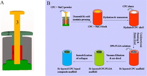
The process of preparing the bi-layered CPC-based composite scaffold is shown in figure (B). The unidirectional porous CPC inside the dense CPC shell was fabricated by unidirectional freeze casting, as described in previous studies [Citation16, Citation22, Citation23]. The CPC slurry was prepared by mixing the sodium alginate solution (2%, w/v) with the CPC powder at a liquid to powder (L/P) ratio of 3.25 ml g−1. The slurry was poured into the tubular CPC shell which was put on a cold plane (–30 °C) to generate unidirectional ice crystals. The frozen samples were freeze-dried to obtain the unidirectional macropores left by sublimation of ice crystals. Then the samples were stored in an incubator with 98% relative humidity at 37 °C for 7 days. The bi-layered CPC scaffold, the porous CPC scaffold without dense shell and the dense CPC column without porous core were designated as b-CPC, p-CPC and d-CPC, respectively.
PLGA was dissolved in dichloromethane (CH2Cl2) at a concentration of 0.20 g ml−1 (w/v) to form a flowable solution. The hydrated b-CPC scaffolds were immersed into the PLGA solution and infiltrated under the low vacuum. After the infiltration procedure, the scaffold samples were air-dried at room temperature for 2 days to eliminate the rest of CH2Cl2. The bi-layered CPC/PLGA composite scaffold was obtained.
Collagen was immobilized on the surface of bi-layered CPC/PLGA composite scaffold to improve its surface bioactivity using NH3 plasma treatment, as described in our previous study [Citation25]. Plasma treatment was performed with a plasma processor (OPS Plasma DL-1, Omega, China) under the following conditions: pressure = 20 Pa, frequency = 13.65 MHz, treatment time = 10 min, input power = 50 W. The NH3 plasma-treated samples were immersed into 4 mg ml−1 (w/v) collagen solution at 4 °C for 3 h. After being freeze-dried, the collagen-immobilized scaffold samples were obtained.
2.3. Scaffold characterization
2.3.1. Phase analysis.
All the CPC samples were dried at 50 °C for 24 h and then milled into powders. The powdered samples were analyzed using x-ray diffraction (XRD; X‘Pert PRO, PANalytical Co., the Netherlands). Data were collected for 2θ from 20° to 60° with a step size of 0.0338.
2.3.2. Morphological characterization.
The microstructure and morphology of the scaffolds were observed by an environmental scanning electron microscope (SEM; Quanta 200, FEI, the Netherlands) and a field emission scanning electron microscope (Nava NanoSEM 430, FEI, the Netherlands). After being dried, the samples were mounted on an aluminum stub by carbon tape and sputtered with gold. Accelerating voltages of 2–15 kV were used to observe the morphology of composite scaffolds.
2.3.3. Porosity.
The porosity of bi-layered CPC scaffold without incorporation of PLGA (PC) was calculated with the following equation:
where dM denotes the density of the CPC scaffolds and dC represents the density of HA which is the hydration product of CPC. The dM was determined by measuring the gross weight and volume of samples, and dC was measured with HA powder by the pycnometric method. The porosity of scaffold after incorporation of PLGA (PPC) was calculated with the following equation:
where WP denotes the weight of PLGA in the composite scaffold (the weight increment after incorporation of PLGA), dP (1.27 g cm−3) is the density of solid PLGA and V is the volume of the scaffold. Each measurement was repeated six times and the average value was calculated.
2.3.4. Compressive strength test.
The compressive strength of the scaffolds (diameter = 11 mm, height = 11 mm) was measured using a universal material testing machine (Instron 5567, Instron, Britain) at a crosshead speed of 0.5 mm min−1. Each measurement was repeated six times and the average value was calculated.
2.4. Rat bone marrow mesenchymal stem cells harvest
Rat bone marrow mesenchymal stem cells (rMSCs) were obtained from bilateral femora of Fischer 344/N syngeneic rats. Both femora were cut away from the epiphysis of the rat. Bone marrow was flushed out of marrow cavity with 15 ml of culture medium minimal essential medium eagle (MEME) containing 10% fetal bovine serum and 1% antibiotics (100 U ml−1 penicillin G, 100 μg ml−1 streptomycin sulfate and 0.25 μg ml−1 amphotericin B). The bone marrow suspension was transferred into a 75 cm2 tissue culture polystyrene flask and incubated at 37 °C in a humidified incubator with 5% CO2. The culture medium was refreshed every 3 days to remove dead cells and wastes produced by metabolism of cells. After about 90% confluence was reached, the rMSCs were passaged.
2.5. Cell culture and cell seeding
The d-CPC composite, b-CPC composite scaffold (ratio of dense area/total cross-sectional area (D/T ratio) = 0.33), and p-CPC composite scaffold were cut into discs with 11 mm in diameter and 2.5 mm in height. After being sterilized by gamma radiation (15 kGy), the discs were put into 24-well plates and pre-wetted in MEME solution for 12 h. rMSCs at passage 1 were used. 350 μ l of cell suspension (1 × 10⁵ cells ml−1) was seeded onto the surface of the samples in 24-well plates. The cell-seeded samples were incubated at 37 °C in a humidified incubator with 5% CO2 for 2 h to allow the cells to adhere onto the sample surface, then 1 ml of culture medium was added to each well to cover the samples. The culture medium was replaced with fresh one every 3 days.
2.6. Cell attachment
After incubation for 12 h, the samples were taken out and washed with PBS for three times, then immobilized with 2.5% (v/v) glutaraldehyde solution at 4 °C for 4 h. The samples were dehydrated with a graded series of ethanol (30, 50, 70, 90, and 100%) and finally dried at room temperature. The morphology of cells on the samples was observed by SEM.
2.7. Cell viability
The viability of rMSCs cultured on the samples was evaluated using a Live/Dead kit (Biotium, USA) according to the standard protocol provided by the manufacturer after 1, 3 and 7 days’ culture. Only ‘Live’ assay was performed in this study. The cell-sample constructs were washed with PBS and incubated in standard working solution at 37 °C for 45 min. After being washed with PBS twice, the constructs were observed with a fluorescence microscope (40FL Axioskop, Zeiss, Germany). In addition, the scaffold constructs were cut along the direction parallel to the pore orientation to observe the penetration of rMSCs into the internal pores.
2.8. Cell proliferation
Cell proliferation was evaluated by WST-8 assay using a CCK-8 kit (Dojindo Laboratories, Japan) according to the manufacturer's instructions. The cell-sample constructs were transferred to a new cell culture plate on day 1, 3 and 7, respectively. 1 ml of MEME solution was added to each well of the plate, followed by addition of 100 μl of CCK-8 reagent. After incubation at 37 °C for 2 h, 100 μ l of upper solution was pipetted to a 96-well plate. The absorbance at 450 nm was measured with an enzyme linked immunosorbent assay reader (Thermo 3001, Thermo, USA). The optical density value was normalized to the number of rMSCs.
2.9. Statistics/data analysis
All data points are an average of at least three replicates and expressed as mean ± standard deviation. Statistical comparisons were performed by Student's t-test for multiple comparisons. Statistical significance for p < 0.05 was denoted by ∗.
3. Results
3.1. Phase analysis
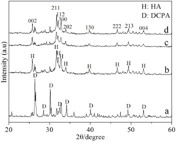
Figure shows the XRD patterns of as-prepared CPC powder and hydrated CPC under different conditions. Hydration product of CPC setting under the normal condition was designated as n-CPC. Under the normal condition, CPC powder was mixed with deionized water at a L/P ratio of 0.4 ml g−1. The XRD pattern of as-prepared CPC powder is shown in figure (a), the narrow and intense diffraction peaks were attributed to DCPA, and the broad weak peaks corresponded to PCCP. With regard to the CPC hydrated under different conditions, peaks of DCPA weakened sharply and characteristic peaks of HA were predominant in the XRD patterns. The full width at half maximum (FWHM) of reflection (002) of HA for n-CPC, c-CPC and p-CPC was 0.1967°, 0.2165° and 0.2358°, respectively.
Figure 2. XRD patterns of the CPC treated under different conditions: (a) mixture of PCCP and DCPA powder; (b) CPC prepared under the normal condition (n-CPC); (c) porous CPC (p-CPC); and (d) CPC processed by cold isostatic pressing (c-CPC).
3.2. Morphology of bi-layered CPC-based scaffold
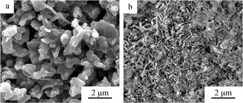
The microstructure of p-CPC and c-CPC is shown in figure . The grain size of p-CPC ranged from 1 to 3 μm, and the size of micropores was about 2 μm. c-CPC exhibited entangled rod-like crystalline grains with 1–2 μm in length and 100–200 nm in width.
Figure 3. Microstructure of porous CPC (a) and dense CPC (b) after hydration.
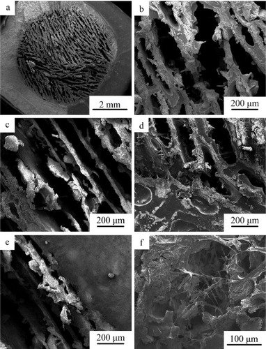
The SEM micrographs of bi-layered CPC scaffolds are given in figure . Lamellar macropores with width in the range of 100–200 μm and length larger than 300 μm were observed at the section perpendicular to the direction of long axis of cylindrical scaffold samples. Unidirectional macropores with 100–200 μm in width were observed at the section parallel to the direction of long axis of cylindrical scaffold samples (figure (c)). No interface separation appeared at the interface between the dense CPC shell and porous CPC core (figure (d)).
Figure 4. SEM images of bi-layered CPC scaffold: (a), (b) the section perpendicular to long axis of cylindrical scaffold; (c) the section parallel to long axis of cylindrical scaffold; and (d) the interface between the porous core and dense CPC shell.
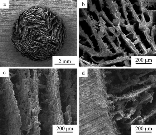
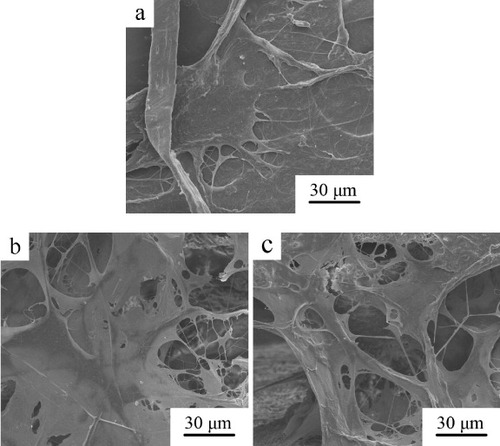
Figure shows microstructure of b-CPC scaffolds after incorporation of PLGA and immobilization of collagen. The unidirectional lamellar macroporous structure of the scaffold was retained and the pore size did not markedly decreased (figures (a)–(c)). The PLGA covered the surface of b-CPC scaffold and the interface between dense shell and porous CPC core was not obvious (figure (d)). The axial direction of unidirectional macropores with the size between 100 and 200 μm in width was parallel to the long axis of dense tubular CPC shell (figure (e)). After immobilization of collagen, abundant reticular collagen was observed filling the macropores of the scaffold (figure (f)).
Figure 5. SEM photographs of bi-layered CPC-based composite scaffold: (a), (b) the section perpendicular to long axis of cylindrical scaffold; (c), (e) the section parallel to long axis of cylindrical scaffold; (d), (e) the interface between the porous core and dense CPC shell; and (f) the morphology of bi-layered CPC-based composite scaffold after immobilization of collagen.
3.3. Porosity
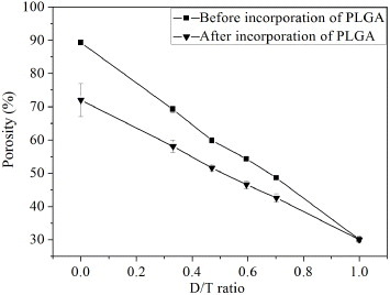
The porosity of the bi-layered scaffold before and after incorporation of PLGA as a function of D/T ratio is shown in figure . The porosity of b-CPC scaffolds ranged from 30 to 90%, which linearly varied with D/T ratio approximately. After incorporation of PLGA, the porosity decreased to the range of 30–72%. As the D/T ratio was 0.33 and 0.47, the porosity of bi-layered composite scaffolds was 58 ± 2% and 52 ± 1%, respectively. The porosity of bi-layered composite scaffold can be facilely controlled by varying the thickness ratio of the dense shell to the porous core.
Figure 6. The porosity of the bi-layered scaffold before and after incorporation of PLGA as a function of D/T ratio.
3.4. Mechanical properties
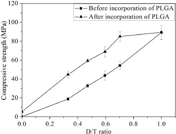
Figure shows the compressive strength of bi-layered CPC scaffold before and after incorporation of PLGA plotted against the D/T ratio. Before incorporation of PLGA, the compressive strength of porous CPC without dense shell was only 0.09 ± 0.01 MPa. After collocation of dense shell, the compressive strength of scaffolds approximately linearly increased with increasing D/T ratio. The compressive strength of scaffold was 16 ± 1 MPa as the D/T ratio was 0.33. When the D/T ratio further increased to 0.47 and 0.60, the compressive strength of the scaffolds increased to 33 ± 2 and 44 ± 5 MPa, respectively. After incorporation of PLGA, the compressive strength of scaffolds further markedly increased, the compressive strength of scaffolds also approximately linearly increased with increasing D/T ratio being in the range of 0–0.70. The compressive strength of composite scaffold without dense shell increased from 0.09 ± 0.01 to 5.4 ± 0.5 MPa. When the D/T ratio was 0.33, 0.47 and 0.70, the compressive strength of scaffolds was 45 ± 4, 59 ± 2 and 85 ± 5 MPa, respectively. However, as the D/T ratio was more than 0.70, the variation of compressive strength of scaffolds nearly reached a plateau. The compressive strength of the dense CPC alone without porous core after incorporation of PLGA just on the sample surface was 89 ± 8 MPa, which was comparable with that without incorporation of PLGA (89 ± 8 MPa).
Figure 7. The compressive strength of bi-layered CPC scaffold before and after incorporation of PLGA plotted against the D/T ratio.
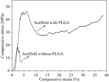
Compressive stress–strain curves of the bi-layered CPC scaffold (D/T ratio =0.33) before and after incorporation of PLGA are exhibited in figure . The catastrophic collapse occurred in the bi-layered CPC scaffold without incorporation of PLGA when the compressive strain reached 4.36%. With respect to the scaffold incorporated with PLGA, a long plateau of compressive stress–strain curve appeared after the maximum value of compressive strength. After the compressive strain reached 24.65%, the values of compressive stress increased again as the compressive load kept increasing. The scaffold maintained well integrity that did not break into pieces as unconfined compression imposed.
Figure 8. Characteristic compressive stress–strain curves of the bi-layered scaffold (D/T ratio = 0.33) with and without incorporation of PLGA.
3.5. Cell attachment
The morphology of rMSCs attached on the d-CPC composite, b-CPC composite scaffold and p-CPC composite scaffold after 12 h of culture is shown in figure . The cells well spread on the surface of d-CPC composite while embedded and well spread in the reticular collagen which filled in the macropores of b-CPC and p-CPC composite scaffold. The cells attached on all the samples were flattened in spindle-shape with abundant filopodia.
Figure 9. Morphology of rMSCs attached on the d-CPC composite (a), b-CPC composite scaffold (b) and p-CPC composite scaffold (c) after 12 h of culture.
3.6. Cell viability
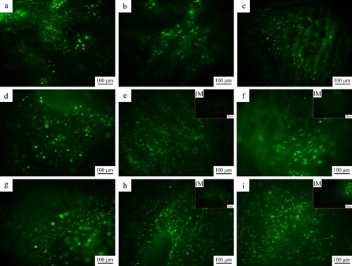
The viabilities of rMSCs on the d-CPC composite, b-CPC composite scaffold and p-CPC composite scaffold are shown in figure . On the first day, the cells well spread and elongated on all the samples. As the culture time prolonged, the cell number on all the samples increased, and the cells retained the spread and elongated morphology. The cells distributed uniformly on each scaffold. On the third day, no cell was observed in the interior of b-CPC composite scaffold and p-CPC composite scaffold. On day 7, considerable cells appeared in the interior of b-CPC composite scaffold and p-CPC composite scaffold.
Figure 10. Fluorescence photographs of rMSCs on the d-CPC composite (a), (d) and (g), b-CPC composite scaffold (b), (e) and (h) and p-CPC composite scaffold (e), (f) and (i) after 1 (a)–(c), 3 (d)–(f), and 7 (g)–(i) days of culture. (IM) denotes the fluorescence photographs of rMSCs in the internal macropores.
3.7. Cell proliferation
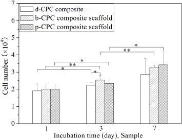
The proliferation of rMSCs on the d-CPC composite, b-CPC composite scaffold and p-CPC composite scaffold is shown in figure . As the culture time prolonged, the cell number on all the samples increased. The cell number on the p-CPC composite scaffold and b-CPC composite scaffold was higher than that on the d-CPC composite. The cells on the p-CPC composite scaffold and b-CPC composite scaffold showed no significant difference. These demonstrate that the rMSCs proliferated well on the bi-layered CPC-based composite scaffold.
Figure 11. The proliferation of rMSCs on the d-CPC composite, b-CPC composite scaffold and p-CPC composite scaffold.
4. Discussion
Application of porous CPC scaffolds in bone defect repair is limited by their brittleness and low strength [Citation5, Citation6]. Many methods have been developed to improve the mechanical properties of porous CPC scaffolds. However, there has not been a breakthrough yet so that the use of porous CPC scaffolds is limited to the bone defects at non-load- or low-load-bearing sites. In the present study, we fabricated a core/shell bi-layered CPC-based composite scaffold with adjustable compressive strength and high toughness, which mimicked the structure of natural cortical/cancellous bone. The dense CPC shell was processed by cold isostatic pressing which produced a dense and macrodefect-free structure [Citation26]. The dense shell and incorporation of PLGA provided the mechanical enhancement of scaffolds synergistically. The unidirectional macroporous core facilitated ingrowth of cells and bone tissues as well as implant fixation [Citation14, Citation25].
XRD analysis revealed that the main hydration products of cold-isostatically pressed CPC (c-CPC) and freeze-dried porous CPC (p-CPC) were poorly crystalline calcium-deficient HA, which was the same as that of CPC hydrated under the normal condition (n-CPC). However, the FWHM of reflection (002) of HA for c-CPC and p-CPC was larger than that for n-CPC, and FWHM of reflection (002) of HA for p-CPC was larger than that for c-CPC. According to the study by Landi et al [Citation27], the crystallinity of HA can be calculated with following equation:
where B002 and XC represents the FWHM (°) of reflection (002) and crystallinity of HA, respectively, and K is a constant equal to 0.24 for a lot of various HA powders. Therefore, the crystallinity of HA for p-CPC and c-CPC was lower than that for n-CPC, and the crystallinity of HA for c-CPC was higher than that for p-CPC. During fabricating the p-CPC, the L/P ratio of CPC slurry was 3.25, which was significantly higher than that of n-CPC (L/P ratio = 0.4). Therefore, the space between PCCP and DCPA particles of p-CPC was larger than that of n-CPC. In this case, the hydration of p-CPC was less complete than that of n-CPC. With regard to c-CPC, contact area of PCCP and DCPA particles were much larger than that of n-CPC and p-CPC, which boosted the hydration of c-CPC compared to n-CPC and p-CPC. However, the low porosity of c-CPC somewhat inhibited water penetration into the interior of c-CPC, which may compromise the hydration reaction of c-CPC. Therefore, the hydration products of CPC processed under different conditions showed different crystallinity and crystal morphology.
CPC can be self-hardening at low temperature so that the porous CPC core well combined with the dense CPC shell instead of local interface separation (figure (d)). CPC scaffold fabricated by unidirectional freeze casting showed unidirectional lamellar macroporous structure and good unidirectional pore interconnectivity but poor 3D interconnectivity. The direction of unidirectional macropores was parallel to long axis of dense tubular shell; therefore, the dense shell did almost not compromise the pore interconnectivity of the scaffold. The width and length of the unidirectional lamellar pores of the scaffold was 100–200 μm and larger than 300 μm, respectively, which provided large enough space and surface for ingrowth of bone tissues and cells. Rose and co-workers [Citation28, Citation29] introduced unidirectional pores into the HA scaffold with randomized pores, and found that the introduction of unidirectional pores facilitated penetration of bone tissues and cells into the centre of the HA scaffold because unidirectional pores improved the transportation of oxygen, nutrient and waste throughout the scaffold implant. Our previous study revealed that the PLGA/CPC composite scaffold with unidirectional pore structure facilitated cell proliferation and penetration into the interior of the scaffold, but the PLGA film on the scaffold compromised the osteoconductivity of CPC matrix because of poor bioactivity of PLGA. After immobilization of collagen on the surface, the cell response of PLGA/CPC scaffold was significantly improved [Citation25]. In the present study, the bi-layered CPC-based composite scaffold also showed well cell attachment, viability and proliferation. The cells penetrated into the internal macropores of the bi-layered composite scaffold as the culture time prolonged. The b-CPC and p-CPC composite scaffold showed better proliferation than the d-CPC composite because the former two scaffolds provided larger surface area for cell attachment and proliferation than the latter one. However, there was no significant difference in cell proliferation between b-CPC and p-CPC composite scaffold. These results demonstrate that the dense CPC shell did not compromise the cell proliferation and penetration into the interior of the scaffold.
It should be noted that various sites of bones have desired compressive strength. For example, the compressive strength of human vertebral bone ranges from 24 to 43 MPa, while the femoral cancellous bone is in the range of 48–80 MPa [Citation30, Citation31]. Therefore, designing scaffolds with facilely controllable compressive strength is meaningful. In this study, the compressive strength of the bi-layered CPC-based composite scaffold can be controlled by varying the thickness ratio of the dense shell to the porous core. Before incorporation of PLGA, the compressive strength of scaffolds tolerably linearly increased with increasing D/T ratio. The compressive strength of c-CPC and p-CPC was 0.09 and 89 MPa, respectively. These indicate that the dense shell predominantly resists the external force. However, porous CPC core was too weak, moreover, the brittleness of the CPC scaffold was still a major problem to be solved. After incorporation of PLGA, the compressive strength and toughness of the bi-layered CPC scaffold were further improved. The compressive strength of scaffold with a D/T ratio of 0.33 was 45 MPa, which was in the range of human vertebral bone. The compressive strength of the scaffold with a D/T ratio of 0.47 increased to 59 MPa, which was in the range of femoral cancellous bone. These demonstrate that the bi-layered CPC-based composite scaffold can be adjusted to meet the requirements for repairing the bone defects at various sites. As the D/T ratio ranged from 0 to 0.7, the compressive strength of the bi-layered composite scaffolds approximately linearly increased with increasing D/T ratio. The PLGA occluded with inner and outer surface of dense CPC shell so that the defects on the surface were remedied [Citation22]. When an external load applies on the bi-layered composite scaffold, PLGA coatings will resist the load; besides, the crack opening and propagation are hindered because the defects on the surface of shell are remedied. As the external load exceeds the maximum that the scaffold can withstand, the CPC matrix will break, while catastrophic collapse will not occur due to excellent toughness of the PLGA coating on the pore wall and scaffold surface. As the external force continues to exert, the PLGA coatings elongate and bridge the crack so that the integrity of the scaffolds can retain even though the scaffolds severely deform [Citation32]. After a long plateau, the compressive stress gradually increased as the strain increased, the reason of which was that the composite scaffolds were compacted without breaking into pieces under the compressive load. As the D/T ratio ranged from 0.7 to 1.0, the stressed area of the strong dense CPC shell was much larger than that of the much weaker porous CPC core, the bearing load by the porous core and the strengthening of PLGA coating on the surface of the composite scaffold can be ignored. Thereby the breakage first occurred in the interior of dense CPC shell under the external load. However, the PLGA coating on the surface still maintained the integrity of the scaffold under a higher external load. Compared to the CPC scaffolds fabricated by the other methods such as leaching out of soluble additive, air bubble trapping, etc [Citation7–Citation9], the bi-layered CPC-based composite scaffold showed higher pore interconnectivity as well as better mechanical performance.
Kaito et al [Citation33] fabricated a bi-layered HA scaffold with porous inner layer and dense outer layer, which was used in the canine lumbar interbody fusion model to evaluate bone conduction and bony fusion. Zhang et al [Citation30] fabricated a tricalcium phosphate scaffold with a compact shell and porous cancellous core that mimicked the characteristics of natural bone. The annexation of dense outer layer significantly improved the compressive strength of the scaffolds. However, the interconnectivity of these bi-layered scaffolds was compromised by the dense outer layer. Moreover, degradation rate of the HA scaffold was very low because it was processed by sintering at high temperature. The bi-layered CPC-based composite scaffold fabricated in the present study had adjustable high strength and excellent toughness. The pore interconnectivity of the bi-layered CPC-based composite scaffold was not obviously compromised due to its unidirectional interconnectivity. The dense CPC shell and porous CPC core hydrated at room temperature instead of sintering at high temperature. Therefore, degradation should be much faster for the scaffold than sintered bioceramics. Moreover, the thickness of the dense CPC shell, which plays a major role in the compressive strength, was easy to control by the mould (figure (A)). As the bi-layered CPC-based composite scaffold is implanted in vivo, the PLGA and porous CPC core will degrade much faster than the dense CPC shell, which provides high strength for the scaffold for a long period of time.
5. Conclusion
In this study, a core/shell bi-layered CPC-based composite scaffold mimicking the structure of natural cortical/cancellous bone was fabricated. The dense CPC shell greatly contributed to the strengthening of the scaffold and incorporation of PLGA further improved its compressive strength and toughness. The compressive strength of the scaffold can be adjusted by varying the thickness ratio of the dense CPC shell to the porous core. The pore interconnectivity of the scaffold was not obviously compromised by the dense CPC shell due to its unidirectional interconnectivity but poor three-dimensional interconnectivity. The bi-layered CPC-based composite scaffold showed well cell attachment, viability and proliferation. These results demonstrate that the bi-layered CPC-based composite scaffold is promising for repair of bone defects at various sites.
Acknowledgments
This work was supported by the National Natural Science Foundation of China (NSFC) under grant numbers 51172074 and 50772037 and the National Basic Research Program of China under grant number 2012CB619100.
References
- IrbeZLocaDVempereDBerzina-CimdinaL 2012 Mater. Sci. Eng. C 32 1690 10.1016/j.msec.2012.04.069
- GinebraM PFernandezEde MaeyerE A PVerbeeckR M HBoltongM GGinebraJDriessensF C MPlanellJ A 1997 J. Dent. Res. 76 905 10.1177/00220345970760041201
- DorozhkinS V 2008 J. Mater. Sci. 43 3028 10.1007/s10853-008-2527-z
- ChowL C 2000 Mater. Res. Symp. Proc. 599 27 10.1557/PROC-599-27
- BohnerM 2010 Eur. Cells Mater. 20 1
- FriedmanC DCostantinoP DTakahiSChowL C 1998 J. Biomed. Mater. Res. 43 428 10.1002/(SICI)1097-4636(199824)43:4%3C428::AID-JBM10%3E3.0.CO;2-0
- SardaSNilssonMBalcellsMFernandezE 2003 J. Biomed. Mater. Res. A 65 215 10.1002/jbm.a.10458
- MontufarE BTraykovaTGilCHarrIAlmirallAAguirreAEngelEPlanellJ AGinebraM P 2010 Acta Biomater. 6 876 10.1016/j.actbio.2009.10.018
- HesarakiSZamanianAMoztarzadehF 2008 J. Biomed. Mater. Res. B 86B 208 10.1002/jbm.b.31008
- Del RealR POomsEWolkeJ GVallet-RegiMJansenJ A 2003 J. Biomed. Mater. Res. 65 30 10.1002/jbm.a.10432
- DevilleSSaizETomsiaA P 2006 Biomaterials 27 5480 10.1016/j.biomaterials.2006.06.028
- FuQRahamanM NDoganFBalB S 2008 J. Biomed. Mater. Res. B 86B 125 10.1002/jbm.b.30997
- SchoofHApelJHeschelIRauG 2001 J. Biomed. Mater. Res. 58 352 10.1002/jbm.1028
- HeFYeJ 2012 J. Biomed. Mater. Res. A 100A 3239 10.1002/jbm.a.34265
- KarashimaSTakeuchiAMatsuyaSUdohKKoyanoKIshikawaK 2009 J. Biomed. Mater. Res. A 88A 628 10.1002/jbm.a.31904
- QiXYeJWangY 2007 J. Chin. Ceram. Soc. 35 1577
- ZhaoLBurgueraE FXuH H KAminNRyouHArolaD D 2010 Biomaterials 31 840 10.1016/j.biomaterials.2009.09.106
- XuH H KWeirM DSimonC G 2008 Dent. Mater. 24 1212 10.1016/j.dental.2008.02.001
- HabrakenW Jde JongeL TWolkeJ GYubaoLMikosA GJansenJ A 2008 J. Biomed. Mater. Res. 87 643 10.1002/jbm.a.31703
- van de WateringF CLavermanPCuijpersV MGotthardtMBronkhorstE MBoermanO CJansenJ A 2013 Biomed. Mater. 8 035012 10.1088/1748-6041/8/3/035012
- XuH H KSimonC GJr 2004 J. Biomed. Mater. Res. A 69 267 10.1002/jbm.a.20124
- QiXYeJWangY 2009 J. Biomed. Mater. Res. A 89A 980 10.1002/jbm.a.32054
- QiXHeFYeJ 2012 J. Wuhan Univ. Technol. Mater. Sci. Edn. 27 92 10.1007/s11595-012-0414-6
- WangXYeJWangYWuXBaiB 2007 J. Biomed. Mater. Res. A 81A 781 10.1002/jbm.a.31059
- HeFLiJYeJ 2013 Colloids Surf. B 103 209 10.1016/j.colsurfb.2012.10.018
- LiJHermanssonL 2000 J. Mater. Sci. 35 5879 10.1023/A:1026733130062
- LandiETampieriACelottiGSprioS 2000 J. Eur. Ceram. Soc. 20 2377 10.1016/S0955-2219(00)00154-0
- RoseF RCysterL AGrantD MScotchfordC AHowdleS MShakesheffK M 2004 Biomaterials 25 5507 10.1016/j.biomaterials.2004.01.012
- SilvaM MCysterL ABarryJ JYangX BOreffoR OGrantD MScotchfordC AHowdleS MShakesheffK MRoseF R 2006 Biomaterials 27 5909 10.1016/j.biomaterials.2006.08.010
- ZhangFChangJLuJLinKNingC 2007 Acta Biomater. 3 896 10.1016/j.actbio.2007.05.008
- NagarajaS 2006PhD Thesis Georgia Institute of Technology 139
- PeroglioMGremillardLGauthierC 2010 Acta Biomater. 6 4369 10.1016/j.actbio.2010.05.022
- KaitoTMukaiYNishikawaMAndoWYoshikawaHMyouiA 2006 J. Biomed. Mater. Res. B 78B 378 10.1002/jbm.b.30498