
Abstract
The authors applied two technologies to improve the efficiency of fluorescent blue organic light-emitting diodes (OLEDs). First, an efficiency-enhancement layer (EEL) was introduced to boost triplet–triplet fusion (TTF). Second, new blue dopants with a higher orientation factor in the emitting layer were developed. Consequently, the external quantum efficiency (EQE) was increased up to 11.5% with Commission Internationale de l’Eclairage (CIE) 1931 color coordinates of (0.138, 0.092). The reported results may lead to EQEs that exceed 14% with fluorescent blue emitters.
Introduction
Organic electroluminescence (EL) has been studied extensively to realize thin, efficient, and stable devices with wide viewing angles and fast response. In recent years, organic EL materials with excellent characteristics have been developed and commercialized for mobile phones and televisions based on organic light-emitting diodes (OLEDs). These materials were obtained as a result of continuing research over two decades. Tang and Vanslyke [Citation1] reported an organic device with a stacked structure in 1987. The authors started research in 1986 that focused on developing blue-emitting materials with a long lifetime. High efficiency and long lifetime were achieved in 1995 by combining fluorescent styryl amine dopants with a distyrylarylene (DSA) host [Citation2]. Based on this new host-dopant system, the blue emitter was commercialized for the first multicolor display in 1999. The styrylamine- or amine-doped systems were found to enhance stable hole injection and efficient emission [Citation3]. Various arylamine dopants with strong blue fluorescence were tested [Citation3]. Until 2004, a lifetime of 7000 h at 1000 cd m−2 for pure blue emission was achieved. The pure blue material was commercialized for the first active display in 2004 [Citation4]. The next section describes the history of improvement for the amine-doped system. The external quantum efficiency (EQE) of the blue devices was improved continuously up to about 6% in 2008 and found to be near the theoretical limit [Citation5]. By 2010, the 25% limit had been overcome by using triplet—triplet fusion (TTF) [Citation6, Citation7]. The third section of this paper describes the TTF results and further improvements made by molecular orientation of blue dopants. An EQE of 11.5% was achieved for deep blue emission [Citation8]. This EQE value is lower than that of phosphorescent devices with heavy-metal complexes. However, deep blue fluorescent materials are still attractive for both industrial and academic researchers because of their pure color and longevity.
History
The lifetimes of devices with a nondoped host were shorter than 1000 h before 1995. It was thought that the practical application of organic EL was difficult. Even though the emission color of styrylamine-doped devices [Citation2] was light blue, the materials were improved, and a practical lifetime of 10 000 h was achieved for the first time [Citation9]. A prototype 5-inch video graphics array (VGA) display to demonstrate video-rate pictures and fast response was reported in 1997. Figure shows the structures of the host and dopant that were commercialized for multicolor displays in 1999.
Figure 1 Structures of DSA host and stylylamine dopant (Ar and R denote an arylene group and a substituent, respectively).
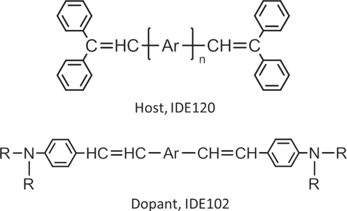
In order to realize full-color displays, pure blue emission was needed. It is possible to shorten the conjugated length of a dopant structure to obtain pure blue emission, but at the same time it was found to be quite difficult to extend the lifetime to over 10 000 h. The blue emitters from various styrylamines and arylamines (figure ) continued to be selected, and a 10 000-h lifetime at an initial luminance (CIE y-coordinate 0.16) of 200 cd m−2 was achieved in 2001 [Citation3], 7000 h at 500 cd m−2 was achieved in 2004 [Citation4], and 12 000 h at 1000 cd m−2 was achieved in 2006. By 2008, the lifetime had been improved up to 11 000 h at an initial luminance of 1000 cd m−2 (CIE y-coordinate 0.133) [Citation5]. The lifetime had been improved more than 10 times over that in 2001, assuming that the luminance acceleration factor was 1.5 power. Simultaneously, pure blue color was achieved. The EQE in 2008 was 5.8%, close to the theoretical limit of the fluorescent EL based on emission from singlet excitation.
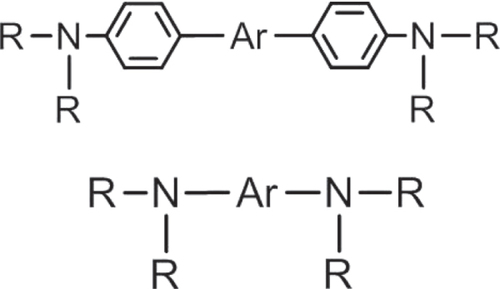
Figure 2 Structures of arylamine dopants (Ar and R denote an arylene group and a substituent, respectively).
Deep blue emission (CIE y-coordinate 0.08) has been obtained via a microcavity effect under a top emission structure [Citation5]. The improvements were all realized through the use of hosts doped with amine dopants. In addition, the latest currently commercialized emitter is based on an amine-doped system. It can be said that this amine-doped system is quite excellent. The next section describes the TTF results and further improvements made by means of dopant orientation.
Basic concept to improve the efficiency of blue fluorescence
Generally, the EQE of fluorescent OLED devices can be described by the following formula:(1)
where γ is the carrier balance factor, φ r is the singlet exciton formation ratio, φ PL is the PL quantum efficiency of the emitter, and φ OC is outcoupling efficiency. At present, almost 100% γ can be realized by optimizing electron and hole injection balance. In addition, φ PL shows a value over 90% with good stability. This paper focuses on how to increase φ r by TTF and φ OC by molecular orientation of the fluorescent emitter.
Triplet–triplet fusion (TTF)
The behavior of triplet excitons generated in an organic layer has been studied theoretically [Citation10]. Triplet excitons (3A*) collide with each other and generate singlet excitons (1A*) by the following formula:(2)
This means that five triplet excitons generate one singlet exciton. Therefore, in addition to the 25% of singlet excitons originally generated, 15% more singlet excitons (75% × 1/5) would be generated additionally. This means that 40% singlet exciton formation would be achieved by using this phenomenon. Generally, this phenomenon has been called triplet–triplet annihilation (TTA). However, the authors call it triplet–triplet fusion (TTF) because additional singlet excitons are generated, not annihilated, by the collision of two triplets. The number of singlet excitons generated by TTF is proportional to the square of triplet exciton density in the layer, which means that it is important for higher efficiency to confine triplet excitons to the emitting layer (EML).
Triplet–triplet annihilation processes in fluorescent OLEDs have been reported [Citation11–Citation13]. In these reports, high EQEs of 11.5% and 8.6% for red and yellow OLEDs, respectively, were achieved by inserting an assist layer containing a blue host material and a green dopant between the emitting layer and the electron-transporting layer. However, it is difficult to apply the assist-layer system for efficiency improvement of blue OLEDs as long as a green component is used. To overcome this problem, the authors have focused on a highly efficient blue fluorescent system with an undoped efficiency-enhancement layer and have found some electron-transporting materials that produce an EQE of over 10% in pure blue fluorescent OLEDs.
Molecular orientation
Recently, molecular orientation has attracted much attention as a way to promote high efficiency in OLEDs. Specific molecular structures that show a horizontal orientation to the substrate have been reported [Citation14]. In addition, specific host and dopant materials show a molecular orientation in blue fluorescence devices that produces high EQEs in doped and undoped emitting systems [Citation15, Citation16].
This paper focuses on the relationship between the molecular orientation of blue fluorescence dopants (BDs) and EQE in OLEDs. The authors demonstrate that BDs with larger ovality bring a larger orientation factor and higher EQE in blue OLEDs. Furthermore, as a result of analyzing current-voltage-luminance (IVL) characteristics, impedance spectroscopy, and transient EL [Citation17], it was determined that the effect of EQE improvement depends only on improvement of outcoupling efficiency by orientation of BD.
Triplet–triplet fusion technology
Function of efficiency-enhancement layer
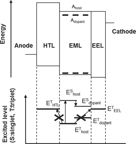
To realize the mechanism of TTF in pure blue OLEDs, an efficiency-enhancement layer (EEL) was inserted between the blue EML and the electron-transport layer (ETL). Figure shows an energy diagram (upper figure) and excited levels of singlet and triplet states (lower figure) in a typical blue fluorescent OLED with an EEL. A hole-transporting layer (HTL) and EEL material with a higher triplet level than emitting materials are necessary to confine the triplet excitons to the EML. Typical HTL materials are likely to have high triplet levels of around 2.5 eV; therefore, the authors focused on EEL material located on the ETL side. Not only is a high triplet level important, but a large electron mobility and the alignment of electron affinity levels are also important. We found a new EEL material, EEL-2, that has almost the same electron affinity level as the blue host material and an electron mobility of about 10−4 cm2 V−1·s at an electric field of 0.25 MV cm−1 (measured by impedance spectroscopy).
Figure 3 Energy diagram and excited level of each layer in an OLED with an EEL.
Device performance [Citation18]
The authors fabricated four types of bottom-emission blue OLEDs with BD-6 and a new material BD-7. All layers were stacked by the evaporation method on indium tin oxide (ITO; thickness 130 nm) substrate.
| (1) | ITO/hole injection layer (HI)/HT/blue host (BH1):BD-6/ET-3/LiF/Al | ||||
| (2) | ITO/HI/HT/BH1:BD-6/EEL-2/ET-3/LiF/Al | ||||
| (3) | ITO/HI/HT/BH1:BD-7/ET-3/LiF/Al | ||||
| (4) | ITO/HI/HT/BH1:BD-7/EEL-2/ET-3/LiF/Al. | ||||
Initial performance at a current density of 10 mA cm−2 and half lifetime at an initial luminance of 500 cd m−2 are summarized in table . BD-7 has the same EL peak wavelength as BD-6. However, it has a more than 10-nm narrower full width at a half maximum of 32 nm compared with BD-6. Therefore, BD-7 can achieve a deep blue of CIEy = 0.08. In addition, the high EQE of 8.6% and high current efficiency of 6.5 cd A−1 can be achieved by combination with EEL-2. Pure blue emitters such as BD-7 would be useful for large OLED televisions with bottom-emission structures that have good angular dependence of color.
Table 1 Performance of BD-6 and BD-7 devices with or without an EEL (J = 10 mA cm−2).
Delayed fluorescence measurement
As mentioned earlier, the TTF process relates to the collision of two excitons. Therefore, an equation for the the time dependence of the TTF process can be written as follows:(3)
T
is triplet exciton density, α is the decrease rate of an intrinsic lifetime of triplet exciton, and β is the decrease rate of collisions of two triplet excitons. By solving the rate equation in the range of small t, the following equation can be obtained:
(4)
EL intensity from the collision of two triplet excitons is proportional to the square of triplet exciton density. Therefore, the square root of the EL intensity by TTF should be described by a linear function of time.
In order to confirm that the high EQE of devices 2 and 4 originated from the TTF mechanism, the transient EL responses of four devices were measured. Transient EL responses were monitored by a photomultiplier tube (R928; Hamamatsu Photonics KK Iwata City, Japan). The photocurrents were entered directly into the input channel of a digital oscilloscope (2440; Tektronix, Inc., Beaverton, OR, USA) with an impedance of 50 Ω. The devices were connected serially to a pulse generator (8114A; Agilent Technologies, Inc., Santa Clara, CA, USA) and another channel of the oscilloscope with an impedance of 50 Ω. The repetition rate was 20 Hz, and the pulse width was 500 μs. The photocurrent signals were averaged on the oscilloscope until the signals became sufficiently smooth, and then they were transferred to a PC. The photocurrents were acquired under 0.1, 2, and 20 μs div−1, and the data were joined into one sequence.
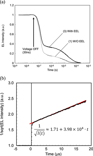
Figure shows the transient EL intensity of device 1 (BD-6 without EEL-2) and device 3 (BD-6 with EEL-2). A pulse voltage corresponding to a current density of 1 mA cm−2 was applied to the device. The two devices exhibited delayed EL components, but it was obvious that device 3 showed larger amount of delayed EL. Furthermore, the inverse square root of the EL decay was well fitted with a linear function of time, which strongly indicated that the delayed EL originated from the TTF process. The intercept of the linear function (t = 0) would be the inverse square of the ratio of the delayed EL component, the so-called TTF ratio, in a constant driving mode. From figure (b), the intercept value was deduced as 1.71. Therefore, the TTF ratio of device 3 was estimated to be 34%.
Figure 4 Transient EL curves of devices 1 and 3: (a) transient EL curves as a function of log-scaled time; (b) inverse square root of transient EL intensity as a function of linear-scaled time.
Molecular orientation of blue emitter
Material properties of blue dopants
Four BDs (A–D) were synthesized focusing on the ovality of the molecule. Molecules with larger ovality are expected to show better molecular orientation. Different electronic properties of BDs produce differences in device performance. Therefore, molecular design was carefully varied to produce similar electronic properties. Table shows the material properties of the four BDs. The singlet energy (EgS) and ionization potential (IP) of BD-B, -C, and -D were described based on the difference from BD-A. The ovality of BDs was calculated assuming the most stable structure of the ground state using the Gaussian (B3LYP/6-31*). The photoluminescence quantum yield (PLQY) in toluene solution had the same value of 80% in the four BDs. The anisotropy of the extinction coefficient in BD evaporated thin film with 100-nm thickness on glass substrate was measured by spectroscopic ellipsometry. The extinction coefficient k is the value at a wavelength of 420 nm (near the absorption peak), and kx or kz corresponds to an orientation that is horizontal or vertical to the substrate, respectively. The orientation factors S and S′ (ratio of emitting dipole parallel to the substrate) were estimated by the following equations. A material with a random orientation shows S = 0 and S′ = 0.666 (2/3).(5)
All BDs have S < 0 and S′ > 0.666, which clearly indicates that all materials show a parallel orientation, and the BDs with larger ovality show a stronger orientation.
In order to analyze the optical effect of BD orientation, we used a measurement of edge emission, which is a well-known method of analysis of the orientation of a dopant material in the EML [Citation16]. However, in this paper, S′ of the BDs in doped films was calculated using the measured kx and kz of the doped films in the longer-wavelength region of the host material’s absorption edge. The extinction coefficient originating from BDs in doped films can be clearly estimated because the energy gaps of the BDs are about 0.2 eV smaller than that of the host material. Figure shows the dependence of S′ on the doping concentration in the case of BD-C. The S′ value is nearly constant independent of the doping concentration. Therefore, it was concluded that the orientation factors of the BD neat films listed in table are also maintained in the doped EMLs of OLED devices. At this time, the mechanism of BD orientation in the host matrix is unclear, and the dependence of the S′ value of BDs on the host material should be carefully studied.
Figure 5 S′ of BD-C doped host film with a thickness of 100 nm.
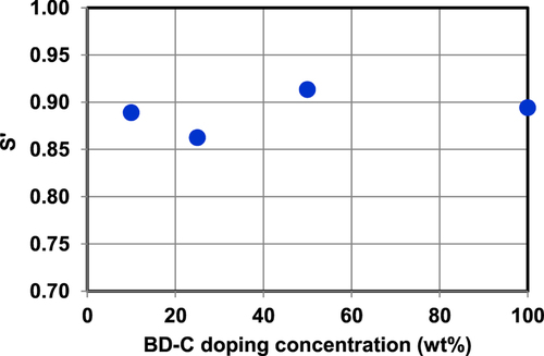
Table 2 Material properties of the four BDs.
Device performance
The authors fabricated four types of bottom-emission blue OLEDs with different BDs. The device structure is ITO(130)/HI(5)/HT1(80)/HT2(15)/BH:BD(25;5%)/EEL(20)/ET(5)/LiF(1)/Al (unit: nm).
Device performance at a current density of 10 mA cm−2 is summarized in table . All devices showed the same driving voltage of around 3.40 V. However, the BDs with larger orientation factors showed higher EQEs, and BD-D showed the largest EQE of 10.1%.
Table 3 Device performance at a current density of 10 mA cm−2.
Confirmation of carrier and exciton mechanisms
There might be other reasons for a high EQE in OLED devices. In general, not only is orientation of the BD molecule a factor, but also better carrier balance or exciton confinement in the emitting layer. In order to confirm that the high EQEs originated mainly from the larger orientation factors, we conducted three types of analysis—IVL, impedance spectroscopy (IS), and transient EL (TEL) measurements—to study the influence of carrier and exciton behaviors. Finally, we simulated the optical effect of BD orientation on the EQE of blue devices. An SI1260/1296 impedance analyzer system was used, and the complex modulus signal was measured by applying direct-current (dc) voltage and 100-mV alternating-current (ac) voltage in the frequency range between 1 Hz and 1 MHz. In the TEL measurement, the emission decay curve after removing the pulse voltage was monitored using a photomultiplier. In both the IS and TEL measurement, the height of the driving voltage was adjusted corresponding to the current density of 10 mA cm−2.
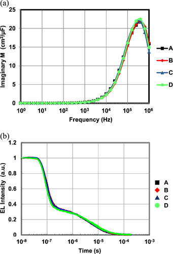
Figure shows the V-J and J-L/J curves of four devices. The V-J curves show the same tendencies, and all devices show maximum L/J at the same J of around 6 mA cm−2. Figure shows the relationship between frequency and the imaginary part of the complex modulus (a) and the results of transient EL measurement (b). All the devices show a maximum modulus at the same frequency of around 4 × 10⁵ Hz. All the devices show the same decay curve for transient EL, which means that they have the same delayed fluorescence ratio of about 30% and the same triplet–triplet collision time constant of 1.4 × 10⁵ (l/s). These results strongly suggest that the devices A–D have the same carrier balance and exciton behavior and that the different EQEs originate purely from the optical effect of the horizontal orientation of BDs.
Figure 6 (a) V-J curves and (b) J-L/J curves.
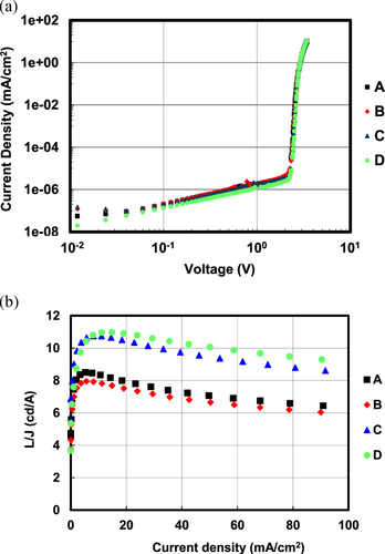
Figure 7 (a) Impedance spectroscopy results and (b) transient EL decay curves.
Upper limit of blue fluorescence efficiency
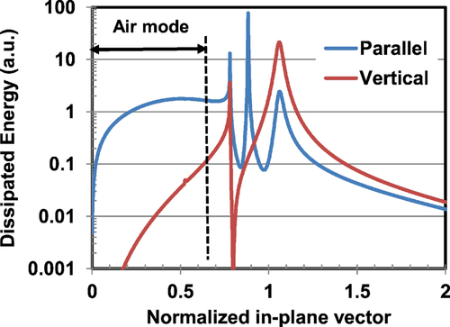
In addition, the authors calculated the photonic mode density of device structure considering the surface plasmon–polariton coupling effect in order to confirm the quantitative effect of BD orientation [Citation19]. Figure shows the results, where the dissipated energy of parallel or vertical dipoles is plotted as a function of normalized wave number vector. The fraction of light extracted outside the device can be estimated by integrating in the ‘air mode’ region of the parallel orientation mode in the figure . The integrated value is 35.1%. Thus one can estimate the outcoupling efficiency of the device by multiplying the value 35.1% by the S′ value.
Figure 8 Calculated photonic mode density of a fluorescent blue device.
Finally, the authors estimated the EQE of an ‘ideal case’. In the ideal case, three factors—carrier injection efficiency, recombination efficiency, and PLQY of the BD—were assumed to be 100%, and the delayed fluorescence ratio was assumed to be 37.5% (singlet exciton formation efficiency 40%) in the case of a TTF device. Figure shows the relationship between EQE and S′ in ideal case i. Experimental values also were plotted. The red line shows the ideal case, and the blue circles show the results of tables and . The performance gap between the ideal case and BD-A–D can be seen. The cause of the gap would be the lower PLQY of 80% and lower delayed fluorescence ratio of about 30%.
Figure 9 Relationship between orientation factor S′ and external quantum efficiency of an OLED (blue circle: results of BD-A–D; red square: modified BDs; red dotted line: ideal case with 100% of PLQY, 40% of singlet exciton formation ratio).
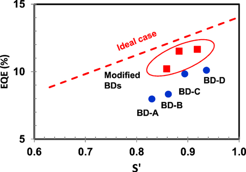
Furthermore, the authors plotted the results of BD structure modification. The red squares show the results with modified BD materials. The modified BDs showed a higher PLQY of 85–90% and comparable S′ values to BD-C and BD-D. As a result, the EQE was successfully improved up to 11.5% with CIE1931 color of (0.138, 0.092). In addition, the LT70 at a current density of 50 mA cm−2 was as high as 250 h. This performance will contribute to realization of the commercialization of large OLED televisions or new types of OLED mobile phones with low power consumption.
Conclusions
In order to improve the efficiency of fluorescent blue OLEDs, two technologies were applied. First, an efficiency-enhancement layer (EEL) with higher triplet energy was introduced between the emitting layer and the electron-transporting layer to enhance the TTF process. The device with the EEL showed a strong delayed-fluorescence component that exceeded 30%. Second, new blue dopants with higher orientation factors in the emitting layer were developed. As a result, the EQE was improved up to 11.5% with CIE1931 color of (0.138, 0.092). Such a high EQE value originated from the enhanced outcoupling efficiency of parallel-oriented blue dopants. The results of this paper may lead to EQEs that exceed 14% in fluorescent blue emitters.
References
- TangC WVanslykeS A 1987 Appl. Phys. Lett. 51 913 10.1063/1.98799
- HosokawaCHigashiHNakamuraHKusumotoT 1995 Appl. Phys. Lett. 67 3853 10.1063/1.115295
- HosokawaCSakaiHFukuokaKTokailinHHironakaYIkedaHFunahashiMKusumotoT 2001 SID Symp. Digest Tech. Papers 32 522 525 522–5 10.1889/1.1831911
- HosokawaCFukuokaKKawamuraHSakaiTKubotaMFunahashiMMoriwakiF 2004 SID Symp. Digest Tech. Papers 35 780 783 780–3 10.1889/1.1821395
- FunahashiMYamamotoHYabunouchiNFukuokaKKumaHHosokawaCKambeEYoshinagaTFukudaTKijimaY 2008 SID Symp. Digest Tech. Papers 39 709 711 709–11 10.1889/1.3069764
- KawamuraMKawamuraYMizukiYFunahashiMKumaHHosokawaC 2010 SID Symp. Digest Tech. Papers 41 560 563 560–3 10.1889/1.3500528
- KawamuraY 2011 SID Symp. Digest Tech. Papers 42 829 832 829–32 10.1889/1.3621459
- OgiwaraTItoHMizukiYNaraokaRFunahashiMKumaH 2013 SID Symp. Digest Tech. Papers 44 515 518 515–8 10.1002/j.2168-0159.2013.tb06258.x
- HosokawaCEidaMMatsuuraMFukuokaKNakamuraHKusumotoT 1997 SID Symp. Digest Tech. Papers 28 1073
- BachiloS MWeismanR B 2000 J. Phys. Chem. 104 7711 10.1021/jp001877n
- SpindlerJ PBegleyW JHatwerT KKondakovD Y 2009 SID Symp. Digest Tech. Papers 41 420 423 420–3 10.1889/1.3256804
- YoungR HLenhardJ RKondakovD YHatwarT K 2008 SID Symp. Digest Tech. Papers 39 705 708 705–8 10.1889/1.3069763
- KondakovD YPawlikT DHatwarT KSpindlerJ P 2009 J. Appl. Phys. 106 124510 10.1063/1.3273407
- YokoyamaD 2011 J. Mater. Chem. 21 19187 10.1039/c1jm13417e
- FrischeisenJYokoyamaDEndoAAdachiCBrüttingW 2011 Org. Electron. 12 809 10.1016/j.orgel.2011.02.005
- FrischeisenJYokoyamaDAdachiCBrüttingW 2010 Appl. Phys. Lett. 96 073302 10.1063/1.3309705
- OgiwaraTTakahashiJKumaHKawamuraYIwakumaTHosokawaC 2009 IEICE Trans. Electron. E92-C 1334 10.1587/transele.E92.C.1334
- OgiwaraTHirokatsuIMizukiYNaraokaRFunahashiMKumaH 2014 J. SID at press
- SmithL HWaseyJ A EBarnesW L 2004 Appl. Phys. Lett. 84 2986 10.1063/1.1712036