
Abstract
The blue phase liquid crystal (BPLC) is a highly ordered liquid crystal (LC) phase found very close to the LC–isotropic transition. The BPLC has demonstrated potential in next-generation display and photonic technology due to its exceptional properties such as sub-millisecond response time and wide viewing angle. However, BPLC is stable in a very small temperature range (0.5–1 °C) and its driving voltage is very high (∼100 V). To overcome these challenges recent research has focused on solutions which incorporate polymers or nanoparticles into the blue phase to widen the temperature range from around few °C to potentially more than 60 °C. In order to reduce the driving voltage, strategies have been attempted by modifying the device structure by introducing protrusion or corrugated electrodes and vertical field switching mechanism has been proposed. In this paper the effectiveness of the proposed solution will be discussed, in order to assess the potential of BPLC in display technology and beyond.
1. Introduction
Liquid crystal (LC) is a state matter intermediate between the solid and liquid phases; it was first discovered by Reinitzer in 1888 [Citation1]. The unique properties of LCs, such as optical anisotropy and response to electric field, made them popular materials for electronic displays. Several subphases exist within the LC phase, such as smectic, nematic and cholesteric subphases, which were described by Friedel in 1922 [Citation2]. In 1888, the discovery of LC by Reinitzer [Citation1, Citation3] involved a unique LC subphase, called the blue phase (BP), which can be found as one cools down the LC from the isotropic phase [Citation4–Citation10]. The BP structure is of chiral nematic LC that is highly twisted. The temperature window of BP is very narrow (0.5–1 °C) and can only be observed between the isotropic and helical phases of cholesteric LC [Citation11]. The BP can be divided into three categories (BPI, BPII and BPIII) depending on the chirality of the LC. The BPIII phase has an almost similar structure to the isotropic phase [Citation12], whereas BPI and BPII are made out of double-twist cylinders packed in cubic lattices [Citation13].
The most noticeable characteristic of BPs is that it demonstrates selective reflection of incident light. Its name is derived from the historical observation of the first BPs studied, which exhibited blue color when observed under polarizing optical microscope. However, the BP does not necessarily show blue coloration [Citation14], as coloration depends on the pitch of the LC within the BP. The BPs have potential to be used in fast light modulators or tunable photonic crystals. However, due to the narrow range of temperature where the BP exists, it is still far from being realized in practical applications [Citation15].
To date, considerable research effort has been expended to widen the temperature window of blue phase liquid crystals (BPLCs), in order to render it viable for commercial applications such as displays and photonic technology. Two main strategies are through the addition of polymer or nanoparticles (NPs). For example, the widening of the temperature range of BPs can be achieved through composite systems which consist of polymers and low molecular weight LC. Kikuchi et al [Citation15] succeeded in expanding the BP temperature range by more than 60 °C through the use of such composite systems. Another way of widening the temperature range of BPLCs is by incorporating NPs, where the NPs accumulate in the lattice disclination lines of the BP and stabilize the overall cholesteric blue structure. Studies from systematic high-resolution have found that the mixing of surface-functionalized NPs with LC can lead in the stabilization of BPIII in a wide temperature window [Citation16].
A hybrid BPLC system was reported by Dierking et al [Citation17] and later Wang et al [Citation18] where a combination of polymer and NPs were used to stabilize and extend the temperature range of the BP. By dispersing the NPs (of diameter ∼30 nm) at a concentration of about 0.5 wt% into the polymer-stabilized blue phase (PSBP) system comprising 5.0 wt% polymers (trimethylolpropane triacrylate; TMPTA) and bifunctional monomer (C6M), the mixture showed an increase in the BP range with a maximum of 41.2 °C for ZnS-doped PSBP and 45.9 °C for ferroelectric BaTiO3-doped PSBP. It is expected that the hybrid (polymer-stabilized NP-doped) method stabilizes the disclination lattice of BPI by both the NPs and polymer chains which is more effective and efficient than by single polymer stabilization or NP dispersion [Citation18]. Moreover, a numerical study and advance concept in material design was discussed briefly by Yoshizawa for stabilizing the BP system [Citation19].
The use of LC in displays was first realized in 1968. George Heilmeier invented a display which was based on the dynamic scattering effect [Citation20–Citation22]. This gave rise to a popularity in black and white displays in calculators and watches in 1970 [Citation23]. In 1971, Schadt, Helfrich and Fergason invented independently at almost the same time the twisted nematic (TN) mode [Citation24–Citation29], which was an important milestone in the development of liquid crystal display (LCD) technology. In 1988, Washizuka and Takeda of Sharp Corporation introduced addressation of LCD pixels using thin film transistor arrays, which enabled fast switching for a large array of pixels. This resulted in the active-matrix full-color full motion LCD, which is the precursor to color LCDs in use today [Citation30].
PSBPLC have been proposed as the next generation LCDs [Citation31, Citation32] due to their advantages of sub-millisecond response time (ten times faster than conventional nematic) [Citation33, Citation34], lack of alignment layer (typically needed) to guide the alignment of LC, and an inherent wide viewing angle characteristic. The BPLC is especially attractive for applications such as large-screen LCDs, as the BP is optically isotropic unlike the nematic phase, therefore providing wide viewing angle and excellent dark state without any compensation films [Citation35]. The Kerr effect arises during the isotropic to BP transition which induces a change in birefringence. It is a nonlinear (quadratic) optical effect, which arises during the reorientation of the LC director upon application of an electric field E. It is expressed as Δn = λKE2, where λ is wavelength and K is the Kerr constant [Citation36–Citation38].
However, there are still some problems in the commercialization of BP devices: (1) the operating voltage is as high as several tens of volts, which limit the use of thin-film transistor as the addressing element for BPLCDs; (2) the low transmittance (∼75%) caused by the low aperture ratio due to the presence of strip electrodes for driving the switching voltage; (3) the poor dark state which forms after a few driving frames, which is induced by the residual birefringence [Citation39] and decreases the contrast ratio [Citation40]; and (4) the switching hysteresis [Citation41] induced by the chirality [Citation42] or polymer network [Citation43] makes consistent gray levels difficult to obtain [Citation44].
There are several solutions that have been identified to lower the operating voltage [Citation45–Citation47] and make hysteresis free BPLC devices [Citation39, Citation48–Citation51]. For example, modifications to the device structure have been proposed, such as the planar in plane switching (IPS) structure [Citation52], interdigitated indium tin oxide (ITO) electrodes [Citation53], the protrusion electrode structure [Citation54], periodic corrugated electrodes [Citation36], double-side in plane switching (DS-IPS) [Citation44], and vertical field switching (VFS) [Citation55]. Recently, a BPLC material with a large Kerr constant (K ∼ 33.1 nm V−2 at λ = 514 nm) was developed, which successfully reduced the driving voltage from 100 to ∼8.4 V [Citation56]. Secondly, wall-shaped and protrusion electrodes have been shown to reduce the operating voltage due to the thick LC layer being driven by the thin electrodes. Unfortunately, the low aperture ratio resulted in a very low transmittance and the fabrication of the electrodes is very difficult. The effect of different shapes of protrusion electrodes have also been investigated extensively but the cost of fabrication limits its practical adoption. An ideal display specification for BPLCs would include a simple electrode architecture for ease of fabrication, coupled with low operating voltage (<10 V) and high transmittance (>90%).
This paper will address the various issues associated with the practical commercialization of BPLC devices, which relies on a wide BP temperature range and also efficient device architecture. First, the background of the physics and chemistry of BPs will be introduced. Then, the strategies for widening the BP temperature range through composite mixtures (NPs or polymer) will be discussed, followed by novel device structures for BPLC devices. Finally an evaluation of the potential applications for BPLCs will be presented, in order to summarize the commercial viability of BPLCs.
2. What are BPs?
2.1. Fundamental properties of BPs
In the study of LCs, BPs are self-organized structures. The BP can be observed in many cholesteric LCs, as there are one or more intermediate phases between the transition of regular helical cholesteric phase and the isotropic phase [Citation57]. These are the cholesteric ‘BPs’, which are thermodynamically stable for a very narrow temperature range, usually less than 1 °C [Citation58]. Although the BPs were first discovery by Reinitzer in 1888 [Citation1], serious investigation on BPs only started in the 1960s, when Saupe [Citation59] found out that BPs were not only optically isotropic, but also exhibited unusually strong optical activity. The optical isotropy of the BP in its unswitched state is due to its twisted (cholesteric) direction arrangement. As an example, normally under a crossed polarizers arrangement, light cannot pass through the BP when there is no external voltage, due to the helical twisting of the directors. However, the application of voltage results in deformation of the director twist, which then allows light to pass through the polarizers. Based on his observation, Saupe proposed that the BPs possess a cubic superstructure, hypotheses which set the groundwork for BPLC studies. In 1973, Coates and Gray proposed the name, ‘BPs’, to define this unusual state and they treated the BP as a LC sub-phase [Citation60]. The BP further characterized by Bragg scattering experiment [Citation61–Citation64] and single crystal structure [Citation65, Citation66], to identify BP 1 (BPI) and BP 2 (BPII) which are body centered and simple cubic structures, respectively. Later, much experimental and theoretical effort was expended in the study of BPLCs such as introducing polymers or NPs or dispersion of gold nanorods to widen the temperature range, by changing the cell structure or increasing the Kerr constant to reduce the driving voltage [Citation23, Citation62, Citation67].
2.2. The structure of BPs
Figure (a) visualizes the local director field of the double-twist cylinder which formed within such a stable area. At the central axis of the cylinder the director is vertical and it twists continuously along any radial direction. Figure (b) shows the double-twist cylinder in the body centered cubic unit cell of BPI and the simple cubic unit cell of BPII, respectively. And figure (c) shows the BPI and BPII unit cells contain disclination lines resulting from the points of intersection between the different directions of director within the cubic cell.
Figure 1. Structure of blue phases [Citation4]. Reproduced with permission from Kikuchi H 2008 Liquid crystalline blue phases Liquid Crystalline Functional Assemblies and Their Supramolecular Structures vol 128 ed T Kato (Berlin: Springer) pp 99–117, with kind permission from Springer Science and Business Media.
![Figure 1. Structure of blue phases [Citation4]. Reproduced with permission from Kikuchi H 2008 Liquid crystalline blue phases Liquid Crystalline Functional Assemblies and Their Supramolecular Structures vol 128 ed T Kato (Berlin: Springer) pp 99–117, with kind permission from Springer Science and Business Media.](/cms/asset/e45d4d65-4938-452c-b61d-ccf1d708c578/tsta_a_11661277_f0001_oc.jpg)
The structure of the BP may be further understood by taking a cholesteric structure as a point of reference. For a cholesteric (chiral) LC, the director twists to form a helix over a certain pitch, P. In contrast the BP takes on a double-twist formation [Citation68], by superimposing three elements of cholesteric LC but with their helical axes rotated from one to another by 120° as shown in figure (a). From figure (b), it can be seen to from a local double-twist structure. This 120° rotation between the three cholesteric helices also impose a hexagonal symmetry, which focus a unit cell generates a two dimensional lattice. The point of intersection between these three helical axes form an s = −1/2 disclination, i.e. the structure is locally frustrated at these intersections [Citation69].
Figure 2. Schematic diagram of the planar hexagonal blue phase. (Author: Panjasan, source: http://en.wikipedia.org/wiki/Blue_phase_mode_LCD.)
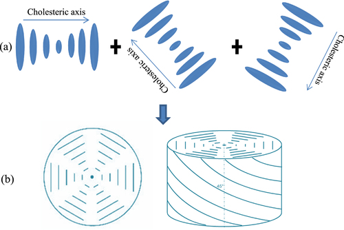
Figure further elaborates on the difference between the double-twist, and the nematic and simple twist structures. Figure (c) shows the structure of the molecule that twisting in all lateral directions which is called a double-twist. As it spreads radially, the double-twist becomes weaker which allows complete formation of double twisting only at the center molecules and its surroundings. Since twisting is allowed in all lateral directions, the molecules are more stable than that in the case of a simple twist at and around the center. Defects occur if the double-twist cylinder expands to a broader area. As mentioned previously, a double-twist structure cannot be an introductory structure that continuously filled a space. However the BP maintains this inconsistency as it is built upon such a double-twisted cylinder structure [Citation70].
Figure 3. Differences between single-twist and double-twist structure [Citation4]. Reproduced with permission from Kikuchi H 2008 Liquid crystalline blue phases Liquid Crystalline Functional Assemblies and Their Supramolecular Structures vol 128 ed T Kato (Berlin: Springer) pp 99–117, with kind permission from Springer Science and Business Media.
![Figure 3. Differences between single-twist and double-twist structure [Citation4]. Reproduced with permission from Kikuchi H 2008 Liquid crystalline blue phases Liquid Crystalline Functional Assemblies and Their Supramolecular Structures vol 128 ed T Kato (Berlin: Springer) pp 99–117, with kind permission from Springer Science and Business Media.](/cms/asset/3d855ec0-2d21-4809-97e4-54c78943c1a9/tsta_a_11661277_f0003_oc.jpg)
Figure illustrates a close up of the void region in the disclination lines. A key solution to a wide temperature stabilization range of the BP is enabled through filling of these disclination regions with NPs or polymer materials. Disclination lines (singularities of the director field) emerge because the void of the unit cell cannot be filled continuously by the double-twist cylinder [Citation11, Citation71]. In the area of the disclination lines, the orientational order parameter vanishes into the isotropic phase. Defects occur at the points where the cylinders are in contact as illustrated in figure . Due to this defect, the structure of the BP is less stable and is limited to a narrow temperature range. It is also due to this fact that the BP exists in the temperature range closest to the isotropic phase [Citation69].
Figure 4. The intersect points of three double-twist cylinders [Citation72]. Reprinted figure with permission from Sethna J P 1985 Phys. Rev. B 31 6278–97, copyright 1985 by the American Physical Society.
![Figure 4. The intersect points of three double-twist cylinders [Citation72]. Reprinted figure with permission from Sethna J P 1985 Phys. Rev. B 31 6278–97, copyright 1985 by the American Physical Society.](/cms/asset/21924959-c446-4495-9bdc-ec6fe8570c4c/tsta_a_11661277_f0004_ob.jpg)
BPIII is somewhat different and has an amorphous structure with the same symmetry as the isotropic fluid [Citation11]. However, there is critical point for the phase transition from BPIII to isotropic, so that at high chirality, BPIII gradually changes to isotropic [Citation73–Citation75]. The director field texture and properties of BP III are not as well understood as those of the crystalline BPs [Citation69, Citation76, Citation77].
3. The Kerr effect in BPLCs
The Kerr effect was discovered by John Kerr in 1875 [Citation78]. The Kerr effect, also known as the quadratic electro-optical effect, explains that the applied electric field will realign the LC director and hence alter the refractive index [Citation79, Citation80]. The sample becomes birefringent, due to this influence, with different indices of refraction for light polarized perpendicular to or parallel to the applied field. Thus, the induced birefringence, Δnind, is given by1 where, λ, K, and E represent the wavelength of the light, Kerr constant and strength of the electric field respectively. This induced birefringence causes the material to act like a wave-plate when light is incident on it in a direction perpendicular to the electric field. Equation (Equation1
1 ) can also be written as [Citation44]
2 Here, (Δn)s is the maximum induced birefringence. When the electric field E is higher than the saturation field Es, the induced Δn saturates at (Δn)s [Citation81]. Given the inherent anisotropic nature of LCs, the optical parameters of BPLCs are well suited to exploit the Kerr effect. To avoid induced lattice distortion, which is also known as the electrostriction effect, and resulting phase transition, a BPLC device should be operate below a critical field [Citation82]. The critical field is defined as the peak voltage where the polymer network remains stable and the structure of the BPLC is reversible. The magnitude of this critical voltage depends on the concentration and structure of polymers employed [Citation83]. A BPLC device will show large hysteresis and longer response time if it is driven above the critical voltage. However, in a separate investigation, Xu et al proposed a mechanism which reduced the hysteresis significantly and dramatically improved response time by suppressing the electrostriction effect using linear polarized UV light during the polymerization process [Citation84]. Due to the Kerr effect, switching can be achieved with a small amount of electric field if a BPLC material contains large values of the Kerr constant [Citation85, Citation86]. However, equation (Equation2
2 ) is effective only when the applied electric field is weak. As the electric field keeps increasing, the induced birefringence will progressively saturate as indicated by the extended Kerr effect model [Citation81]
3
Expanding equation (Equation33 ) the Kerr constant can be deduced as:
4
From equation (Equation44 ), high Δns and low Es play similarly significant roles for improving Kerr constant.
4. Expanding the stable temperature range of BP through composite BPLC mixtures
As mentioned previously, the temperature range for BPLC is limited to a few degrees (0.5–2 °C), which hinders the application of BP in commercial devices. Numerous attempts have been made to broaden the temperature range of the BP, such as using homogeneous mixture of LCs and NPs [Citation16], and polymer stabilization [Citation15]. Stabilization in the temperature range a of few degree centigrade attained for various methods for instance, using a mixture of chiral and bent-core LCs [Citation87] and LC quaternary mixtures [Citation88]. Kitzerow et al [Citation89] formed stabilized BP structures in 1993, using reactive LC monomers, that can be photo-polymerized, which then did not demonstrate any dynamic switching behavior as all of the molecules were polymer stabilized. In 2002, Kikuchi et al described a non-reactive BPLC stabilized through a small amount of polymer (∼8 wt%). This polymer addition causes the cross-linking polymer network, which is selectively concentrated in the disclination cores. The temperature interval of BPLC has been expanded to more than 60 °C, containing room temperature (−13 to 52.85 °C) by stabilized the lattice structure of BP. Additionally, a fast electro-optical switching property was retained for this mixture [Citation15]. This method has opened a new pathway for display and photonic applications [Citation13].
4.1. NP induced stabilization of BP
Since 2009, the suspension of NPs in LCs has been an attractive topic for technological and scientific interest. The motivation for this interest arises from the fact that properties that have not been observed in the pure material appear as a result of the interaction between the nano-sized particles and the anisotropic host and various LC phases act as platforms to drive self-organization assisted NP assembly [Citation90]. However, there are many approaches on mixing NPs with uniaxial anisotropic materials such as nematic LCs [Citation91–Citation93] and BPs [Citation94–Citation97]. Most recently, Yoshida et al reported the extension of the temperature interval of cholesteric BPs by doping gold NPs [Citation90] and Karatairi et al reported the expansion of the temperature interval of BP by doping CdSe NPs [Citation16].
Yoshida et al employed the gold NPs (diameter 3.7 nm), which were dispersed in the material by the sputter-doping technique. The BP-exhibiting LC material used was a mixture, shown in table .
Table 1. Nanoparticles doped as composition [Citation90].
It was found that with the incorporation of spherical gold NPs, the temperature range of BP expanded from 0.5 to 5 °C and decreased the clearing temperature by approximately 13 °C. This observation was attributed to a decrease in the free energy caused by self-organization-assisted NP assembly, which helped stabilize the BPLC over a larger temperature range. Ravnik et al reported that NPs doped in BPs were positively trapped in the disclination lines, therefore elastic interactions occur [Citation98]. It is assumed that, at first freely moving NPs became locked in, once they met a disclination line, and so on the volume and the energy associated with the disclination lines were consequently decreased. An imaginable model of this assumption is illustrated in figure , where the double-twist helical structure indicated by the cylinders.
Figure 5. Blue phase stabilized by gold nanoparticles which trapped in the disclination lines [Citation90]. Figure reprinted with permission from H Yoshida et al 2009 Appl. Phys. Express 2 121501, copyright 2009 The Japan Society of Applied Physics.
![Figure 5. Blue phase stabilized by gold nanoparticles which trapped in the disclination lines [Citation90]. Figure reprinted with permission from H Yoshida et al 2009 Appl. Phys. Express 2 121501, copyright 2009 The Japan Society of Applied Physics.](/cms/asset/b57d0bf4-8af1-47c2-82cf-eb2edee92fd7/tsta_a_11661277_f0005_oc.jpg)
Table also shows the phase transition temperature of the samples demonstrated by Yoshida et al successfully extended the temperature range by the addition of gold NPs.
Table 2. Phase transition temperature before and after nanoparticles doping [Citation90]; (Ch—cholesteric phase and Iso—isotropic phase).
In a separate investigation, Karatairi et al studied the effect of adding CdSe (average diameter 3.5 nm) NPs to chiral LCs, CE8 and CE6 respectively. The size of nanocrystal and the morphology of the semiconducting NPs are shown in figure .
Figure 6. Schematic of CdSe NPs with oleyl amine (OA; left), transmission electron microscopy image of CdSe NPs (right) [Citation16]. Reprinted figure with permission from E Karatairi et al 2010 Phys. Rev. E 81 041703, copyright 2010 American Physical Society.
![Figure 6. Schematic of CdSe NPs with oleyl amine (OA; left), transmission electron microscopy image of CdSe NPs (right) [Citation16]. Reprinted figure with permission from E Karatairi et al 2010 Phys. Rev. E 81 041703, copyright 2010 American Physical Society.](/cms/asset/b8889a30-ffd9-4d8e-87df-ccf593776e10/tsta_a_11661277_f0006_oc.jpg)
For a mixture of CE8 and CdSe NPs, it was seen that at x = 0.02 (where x is the mass ratio of NPs and LC) provides an optimal phase widening of 20 °C. However, no significant phase widening is observed in the mixture of CE6 and CdSe NPs. For example, at x = 0.02 there was no evidence of BPIII phase, whilst x = 0.005 the presence of the BPIII phases was indicated (figure ).
Figure 7. Phase diagrams for CE8 + CdSe mixtures (left) and CE6 + CdSe mixtures (right) [Citation16]. Reprinted figure with permission from E Karatairi et al 2010 Phys. Rev. E 81 041703, copyright 2010 American Physical Society.
![Figure 7. Phase diagrams for CE8 + CdSe mixtures (left) and CE6 + CdSe mixtures (right) [Citation16]. Reprinted figure with permission from E Karatairi et al 2010 Phys. Rev. E 81 041703, copyright 2010 American Physical Society.](/cms/asset/af485c9a-fbe5-4371-9ddc-aa587f9c4804/tsta_a_11661277_f0007_ob.jpg)
The mechanism that increases the temperature range of BPIII phase can be explained by the fact that, the disclination lines are almost entirely saturated with NPs so that it may achieve a wider temperature shift. In addition, NPs are possibly distributed non-uniformly inside the disclination lines, and stabilization of the shapeless BPIII type structure is more easily achieved, compared to the more ordered BPI and BPII structures. The proposed approach also suggests that the increase of NPs have a tendency to increase the disclination length within the structure, because the existence of NPs strongly decreases the condensation term. This process can be very useful for widening the BP temperature range, if NPs are strongly concentrated with disclination lines, which can be imposed by suitable surface treatment of NPs and their size [Citation16].
4.1.1. Electro-optical properties of NPs doped BPLC
In this section, we will discuss NPs doped BPLC within the context of electro-optical performance. Wong et al [Citation67] studied the dispersion of gold nanorods (AuNRs) in a BPLC system and investigated their optical and thermal properties using various wt% of AuNRs. It was found that they expanded the BP temperature range by approximately 3.2 °C with 0.004% AuNRs. Later they have investigated the optical properties of 0.06% AuNRs dispersed BP samples, sandwiched in IPS cells of 5 μm electrode spacing, line width and cell gap. Compared to switching voltage for the pure BPLC (49.4 V) and PSBPLC (∼140 V) the driving voltage of BPLC with dispersed AuNRs is low, at 41.9 V.
In a separate investigation, Hwang and Chien [Citation99] reported a new technique to control the electro-optical properties of BP by adding aerosol NPs in a BPLC system. They reported that hydrophilic AG-d-BP samples reduced the switching voltage up to 64% compared to the pure BPLC. The switching voltage for 0.1% hydrophilic AG-d-BP mixture was 32 V compared 50 V for pure BPLC.
Wang et al [Citation100] added another significant discovery in the topic of NP stabilized BPLCs where they dispersed a small amount of ZnS NPs in a BPLC system. Additionally, in a separate experiment Wang demonstrated a BPLC system with ferroelectric NPs [Citation101]. In both reports, hysteresis-free electro-optical switching was observed. BPLC composites doped with ZnS NPs showed an increasing BPI range with the widest BP phase corresponding to 15.6 °C, and hysteresis-free switching with Von of 75 V was achieved. In comparison, for ferroelectric NPs-doped BPLC system, Wang reported a BPI temperature range with a maximum BPI phase of 16.7 °C, and BPI doped with 0.7 wt% BaTiO3 NPs showed a hysteresis free switching with a driving voltage of 42 V. For reference, for both investigations the NP size and device architecture were comparable. The diameter of the ZnS NPs were ∼33 nm and BaTiO3 NPs were ∼30 nm. For both cases, an IPS cell with the following parameters: electrodes width 5 μm, electrodes gap 5 μm and cell gap 10 μm, were used. The temperature range of BPI was extended, due to the suppression of the volume and free energy around the disclination core through the introduction of NPs in the BP system. Moreover, large dipole moments of the NPs enhanced the anchoring energy of LC molecules in the case of ZnS NPs, were able to significantly reduce the driving voltage [Citation102, Citation103]. The ferroelectric NPs doping further improved the switching voltage through reduction of by more than 40% compared with ZnS NPs dispersed BPLC system due to the (1) a spontaneous strong polarization field (2) increasing dielectric constant and decreasing device parameter (such as electrode gap) which help to generate a uniform strong electric field followed by improving Kerr effect.
4.2. Polymer stabilization of BPs
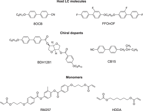
PSBPLCs demonstrate an acceptably wide mesogenic temperature window that includes the room temperature. In order to synthesize PSBPLC, a small amount of photoinitiator (∼0.5%) and monomers (∼8%) are added to the host LC (highest percentage of the system ∼86–92%) and chiral dopant (∼8–14%). Examples of host, chiral dopants and monomer structures are shown in figure .
Figure 8. Examples of nematic host LC, chiral dopants, and monomers.
4.2.1. Characteristics of LC in the room temperature PSBPLC mixture
In the PSBPLC material system, the nematic LC forms the bulk of the mixture. Hence, it plays important role which influence the performance of the PSBPLC device [Citation104] such as driving voltage, temperature range, and response time. To achieve a wide temperature range PSBPLC, a wide ranges nematic host LC is required [Citation105–Citation107]. Generally, the lower temperature limit is of less concern compared to the higher temperature limit, which is mainly defined by the isotropic to nematic clearing point of the LC host [Citation108]. Moreover, the addition of monomers and photoiniatiors in the PSBPLC system has an inclination to lower the clearing temperature (nematic to isotropic temperature) compared to the pure nematic. Thus, a nematic LC host with a clearing temperature Tc > 80 °C is preferred.
When an electric field (E) is applied to a BPLC composite, the LC molecules reorient parallel to the electric field if Δ∊ > 0, and perpendicular to the electric field if Δ∊ < 0, where Δ∊ is the dielectric anisotropy of the LC. The molecular reorientation of LC in electric field results in birefringence. In an IPS device, the on-state voltage (Von) is inversely proportional to the square-root of K [Citation27]. The Kerr constant (K) of a BPLC is given by [Citation28]:5 where, k,
and
are the elastic constant, intrinsic birefringence, and dielectric anisotropy of the nematic host LC. The pitch length is denoted by
Equation (Equation5
5 ) indicates that, a LC with high
and large
is extremely needed to increase the Kerr constant [Citation109]. The response time of a PSBPLC material is given by [Citation110]:
6
In the BPLC system γ1 is the rotational viscosity. This is intimately related to the chiral dopant and the host LC. To achieve fast response time a low viscosity host LC preferable [Citation111]. Because from equation (Equation66 ), response time (τ) is proportional to viscosity (γ) and inversely proportional to elastic constant (k). So as viscosity decreases and elastic constant increases, fast response time can be achieved [Citation112].
The inclusion of chiral dopants induces double-twist in BPs [Citation113]. BPs only appear as the chirality (q0 = 2π/P) exceeds a certain value. There are two ways to increase chirality of BPLC: (1) by increasing the concentration of chiral dopant or (2) by employing a chiral dopant containing a high helical twisting power (HTP) [Citation114]. The melting point of chiral dopant is also an important consideration to select a chiral dopant. For an example, a very low meting point (∼4 °C) chiral dopant (CB15) is shown in figure . As a result, after mixing the chiral dopant with the host LC, the clearing temperature drops substantially as compared to the host LC. In order to widen the temperature range of BPLCs, a higher melting point chiral dopant is desirable whilst retaining good solubility [Citation108].
The choice of monomer is essential in determining the stability of the BPLC [Citation115–Citation117]. Generally, a PSBPLC requires two types of polymer: bifunctional (e.g. RM257) and mono-functional (e.g. EHA or C12A) [Citation118]. Polymer stabilized LCs describe systems in which a polymer network is formed within an anisotropic LC matrix. During the polymerization process a bi-continuous system is formed, where a continuous polymer network permeates a continuous LC phase shown in figure . The structure and order of the LC phase are transferred onto the polymer network, which thus mechanically stabilizes the phase it was formed in [Citation119].
Figure 9. BPI stabilized by the polymer concentrated in the disclination lines [Citation15]. Reprinted by permission from Macmillan Publishers Ltd: H Kikuchi et al 2002 Nat. Mater. 1 64–8, copyright 2002.
![Figure 9. BPI stabilized by the polymer concentrated in the disclination lines [Citation15]. Reprinted by permission from Macmillan Publishers Ltd: H Kikuchi et al 2002 Nat. Mater. 1 64–8, copyright 2002.](/cms/asset/dc5c38ee-1c3c-4e9f-ab10-b0274fd1eb08/tsta_a_11661277_f0009_oc.jpg)
By using a small fraction of polymer (8 wt%) in the overall BPLC mixture, a non-reactive BPLC can be stabilized as shown by Kikuchi et al in 2002 [Citation15]. This was achieved by varying the percentage of the mono-functional monomers EH7 in the mixture. For example, an optimal condition of 1.6 mol% EHA results in a polymer stabilized BP range of >60 °C and the texture of this BP can be seen in figure .
Figure 10. Polarizing optical microscopy image of PSBPLC. BPI at 46.3 °C (left) and BPI at 23.9 °C (right) [Citation15]. Reprinted by permission from Macmillan Publishers Ltd: H Kikuchi et al 2002 Nat. Mater. 1 64–8, copyright 2002.
![Figure 10. Polarizing optical microscopy image of PSBPLC. BPI at 46.3 °C (left) and BPI at 23.9 °C (right) [Citation15]. Reprinted by permission from Macmillan Publishers Ltd: H Kikuchi et al 2002 Nat. Mater. 1 64–8, copyright 2002.](/cms/asset/ccd6c6f6-4661-49b5-b3de-248c021a5739/tsta_a_11661277_f0010_oc.jpg)
In 2005, Coles and Pivenko also reported that, in dimer LCs with large flexoelectricity, the temperature range of the BP was more than 44 °C [Citation88]. LC dimers are formed by linking two mesogenic groups by an alkyl chain spacer [Citation120, Citation121]. Dimeric structures depend upon the number of carbon atoms in the spacer [Citation122]. The nematic-isotropic transition temperature is found to alter as the number of carbon atoms in the alkyl spacer changes from odd to even [Citation123]. Yoshizawa and co-workers reported that a mixture of T-shaped molecules and the binaphthyl derivative succeeded in forming the BP temperature ranges of 13 and 29 °C, respectively [Citation124, Citation125]. Some other methods such as adding hydrogen-bond LCs have also been used to expand the BP temperature range [Citation126]. The cross-linked polymer network is selectively concentrated in the disclination cores and the lattice structure of the BP is stabilized, thus extending the BPLC temperature range.
5. The response of the BPLCs to electric field
The influence of electric field on the structural manners of LC systems exhibiting BPs has been a topic of extensive experimental and theoretical attention. Interesting phenomena that have been investigated include the deformation of the BP unit cell, the reorientation of single crystals, and the total destruction of the three dimensional symmetry, resulting in a cholesteric structure [Citation127]. Kerr-effect-induced isotropic-to-anisotropic transition in BPLCs has the possibility to become future generation display technology because it shows following four attractive features: (1) its response time is in the sub-millisecond range [Citation33] which is almost ten times faster than the existing nematic LCDs; (2) it allows color-sequential display with a red, green, and blue light-emitting diode backlight, by this features the conventional pigment color filters can be eliminated; (3) does not involve any alignment layer to guide LC director to facilitate the fabrication process simplified; and (4) its viewing angle is wide and symmetric [Citation128–Citation130] because the voltage-off state is optically isotropic and voltage-on state forms multi-domain structures [Citation54]. At the voltage-on state, although electric field induces birefringence and the LC index ellipsoid is elongated, the overall cubic symmetry of the BPLC is not changed. This again leads to a symmetric view of the LCD. Due to these features which are different from conventional nematic LCs, the iso-brightness contour of the IPS BPLC cell is more symmetric. However, two most important technical challenges need to be overcome: high operating voltage (∼50 Vrms) and relatively low transmittance (∼65%), before widespread applications can take off [Citation36].
Innovations in BPLC device structure for obtaining low voltage and high transmittance are driven by two main challenges: (1) high driving voltage; and (2) low transmittance [Citation85]. The driving voltage of a PSBPLCD is directed by both device structure and Kerr constant of the employed material [Citation54, Citation131]. From a material perspective, a large Kerr constant is desirable [Citation132]. In recent times, a BPLC mixture with a large K ∼33.1 nm V−2 has been developed by Chen et al [Citation133]. This new material will definitely speed up the emergence of BPLCDs. On the device viewpoint, several BP LCD structures such as protrusion electrodes [Citation54, Citation134], wall-shaped electrodes, corrugated electrodes and double-penetrating fringe fields indicate a very positive trend to reduce the driving voltage [Citation135–Citation138] to the targeted 10 V. However, this is currently achieved with a sacrifice in transmission performance [Citation139].
5.1. BPLC displays with corrugated electrodes
Jiao et al [Citation36] proposed a low operating voltage (<10 V) and high transmittance (∼85.6%) PSBPLC display containing periodic corrugated electrodes as shown in figure . This device architecture creates a strong horizontal electric field component, and more importantly this field penetrates deeply into the LC medium meaning jointly these two factors contribute to lower the driving voltage to ∼9.9 Vrms. The rms value is the square root of the mean (average) value of the squared function of the instantaneous values. The term rms, refers to time-varying sinusoidal voltages, currents or complex waveforms yields the magnitude of the voltage over one period of the sinusoidal wave. Simultaneously, the electric field created by such an arrangement is uniformly circulated across the entire pixel area and by this can obtain high transmittance (∼85%). To broaden the viewing angle a biaxial compensation film has been used. As compared to typical dimensions of patterned IPS electrodes, the electrode width (W) is quite large in this device (∼40 μm). The top substrate is coated with common electrode (without patterning) whilst bottom substrate is coated with pixel electrodes. Furthermore, a BPLC material with K ∼ 12.7 nm V−2 is assumed.
Figure 11. Schematic view of PSBPLCD architecture with corrugated electrodes [Citation36]. Reprinted with permission from M Jiao et al 2010 Appl. Phys. Lett. 96 011102. Copyright 2010, AIP Publishing LLC.
![Figure 11. Schematic view of PSBPLCD architecture with corrugated electrodes [Citation36]. Reprinted with permission from M Jiao et al 2010 Appl. Phys. Lett. 96 011102. Copyright 2010, AIP Publishing LLC.](/cms/asset/d8c8e075-7325-465b-adc2-57373419fa20/tsta_a_11661277_f0011_oc.jpg)
Jiao et al investigated voltage-dependent transmittance (V–T) curves of the BPLC device at λ = 550 nm, with variation in misalignment between the top and bottom electrodes, as shown by figure . For an ideal case, the switching occurs at ∼9.9 Vrms and the highest transmittance reached 85.6% [Citation36].
Figure 12. Normalized V–T curves of the PSBPLCD with corrugated electrodes [Citation36]. Reprinted with permission from M Jiao et al 2010 Appl. Phys. Lett. 96 011102. Copyright 2010, AIP Publishing LLC..
![Figure 12. Normalized V–T curves of the PSBPLCD with corrugated electrodes [Citation36]. Reprinted with permission from M Jiao et al 2010 Appl. Phys. Lett. 96 011102. Copyright 2010, AIP Publishing LLC..](/cms/asset/f35204fd-1394-4b52-af36-30994a2e0db0/tsta_a_11661277_f0012_oc.jpg)
When the misalignment i.e. the horizontal alignment difference between top and bottom electrodes was 0.25 μm, the change in V–T curve was negligible. By increasing the misalignment to 0.50 μm, Von fell to ∼9.7 Vrms and transmittance reached 82.4%. From figure , the V–T curves overlap with each other when V < 9 Vrms, which means the device is insensitive to horizontal shift if it was driven lower than 9 Vrms, where the transmittance was maintained at ∼80%. Other parameter variations, such as enhancing the inclination angle of electrodes or a thinner cell gap are also effective in reducing the driving voltage. For example, by an increased inclination angle, the horizontal component of the induced birefringence was enhanced and the effective path length of incident light is increased, thus with a lower voltage, expected phase retardation can be achieved. Furthermore, when the cell gap decreased, the optical path length dopl is decreased; but on the other hand the induced birefringence (Δn) increased in quadratic manner due to the stronger electric field. Summarily, since phase retardation is proportional to doplΔnnind, a lower driving voltage can result in the same phase retardation in a thinner cell gap. Moreover, the dead zones become narrower in a thinner cell and thus transmittance will be improved [Citation36]. Also by increasing the electrode width, transmittance can be increased. As the electrode width increased, the dead zones decreased because dead zones were found at every turning edge area. Thus, the induced birefringence along the vertical direction at every turning edge will be low as it makes no contribution to phase retardation, resulting in high transmittance.
5.2. Protrusion electrodes for BPLC devices
Rao et al reported a BPLC cell with protrusion electrode structure shown in figure , where the two electrodes (common and pixel) form a trapezoid shape [Citation54] of following dimensions: bottom width (w1), top width (w2), height (h) and space (l) between electrodes. This electrodes structure, not only generates strong electric field between the pixel and common electrodes (horizontally) but also penetrate deeply into the LC bulk region (in a vertical direction) which plays significant role to reduce operating voltage. This type of device structures have been widely used in multi-domain vertical alignment mode LCDs for capturing wide viewing angles. Thus, the fabrication process of protrusion electrodes (by coating ITO on top of protrusions) is not a technical hurdle. A typical protrusion electrode with w1 = 2 μm, w2 = 1 μm, h = 2 μm, and l = 4 μm is shown in figure , the highest transmittance obtained with this structure is ∼71% at 17 Vrms [Citation54].
Figure 13. Cross section view of the BPLCD with protrusion electrodes [Citation54]. Reprinted with permission from L Rao et al 2009 Appl. Phys. Lett. 95 231101. Copyright 2009, AIP Publishing LLC.
![Figure 13. Cross section view of the BPLCD with protrusion electrodes [Citation54]. Reprinted with permission from L Rao et al 2009 Appl. Phys. Lett. 95 231101. Copyright 2009, AIP Publishing LLC.](/cms/asset/9c4df52d-71c6-45cd-a7c7-974ec9916211/tsta_a_11661277_f0013_oc.jpg)
Figure 14. Normalized V–T graphs of the BPLCD for protrusion electrodes with different electrode dimensions [Citation54]. Reprinted with permission from L Rao et al 2009 Appl. Phys. Lett. 95 231101. Copyright 2009, AIP Publishing LLC.
![Figure 14. Normalized V–T graphs of the BPLCD for protrusion electrodes with different electrode dimensions [Citation54]. Reprinted with permission from L Rao et al 2009 Appl. Phys. Lett. 95 231101. Copyright 2009, AIP Publishing LLC.](/cms/asset/aba65404-d2a1-4dfd-8755-89af1f87b3f7/tsta_a_11661277_f0014_oc.jpg)
Decreasing the spacing width l, will reduce the on-state voltage, due to the strong lateral electric fields. However, this is compromised by a decrease in transmission. When the top of trapezoid w2 increased in length this resulted in a more uniform lateral electric field, again at the cost of lower transmittance. Likewise, a larger taper angle will have a similar effect. The low transmittance was exacerbated by the presence of a ‘dead zone’, i.e. a region above the electrodes where the vertical field does not contribute to transmittance. One solution was to increase the height of the electrode in order to minimize the ‘dead zone’, but for higher electrode profiles (h > 4 μm) the fabrication process becomes more difficult [Citation54].
5.2.1. Enhanced protrusion electrodes for BPLC device
An enhanced protrusion electrode was proposed by Li et al [Citation139] for displays which increased transmittance whilst maintaining a low driving voltage. The structure of the enhanced protrusion electrode architecture is shown in figure where two different electrodes are coated on each side of a protrusion such as one side-wall of a protrusion is coated with pixel electrode, and the other is with common electrode. The electric field distribution between protrusions is similar to the conventional protruded structure, thus low operating voltage is still maintained. On the other hand, dead zone on the top of the protrusions was eliminated, because of the IPS-like arrangement on the top of the protrusions was maintained. This is similar to an IPS configuration, it generated horizontal fields and induced transmittance. As a result, the total transmittance was amplified by elimination of the dead zone which exists in normal protrusion electrodes.
Figure 15. BPLCD with enhanced protrusion electrodes [Citation139]. © 2011 IEEE. Reprinted, with permission, from Y Li and S T Wu 2011 J. Display Technol. 7 359–61.
![Figure 15. BPLCD with enhanced protrusion electrodes [Citation139]. © 2011 IEEE. Reprinted, with permission, from Y Li and S T Wu 2011 J. Display Technol. 7 359–61.](/cms/asset/d3251858-5169-48da-9d82-505c399b4245/tsta_a_11661277_f0015_oc.jpg)
A comparison of the transmission of enhanced protrusion electrodes with normal protrusion electrodes can be seen in figure .
Figure 16. V–T curves of the BPLC for conventional protrusion structures versus new protrusion structures [Citation139]. © 2011 IEEE. Reprinted, with permission, from Y Li and S T Wu 2011 J. Display Technol. 7 359–61.
![Figure 16. V–T curves of the BPLC for conventional protrusion structures versus new protrusion structures [Citation139]. © 2011 IEEE. Reprinted, with permission, from Y Li and S T Wu 2011 J. Display Technol. 7 359–61.](/cms/asset/217291c9-77f1-450b-b813-ccd6a960b0cf/tsta_a_11661277_f0016_oc.jpg)
5.3. Double sided IPS electrodes for BPLC devices
A conventional IPS structure is shown in figure (a) where only in the bottom of the substrate of the IPS electrodes were etched thus creating a lateral electric field. Here, width, electrode gap and cell gap are represented by w, l and d respectively. In comparison, a double sided IPS architecture was shown in figure (b), reported by Chen et al where in the top of the substrate the IPS electrodes are also etched and placed correspondingly with the center of the strip electrode gap on the bottom substrate. It is evident that alternating position of the top and bottom electrodes in DS-IPS electrodes can induce more horizontal fields than conventional IPS electrodes [Citation44]. The index of refraction here is higher than that of the typical IPS architecture; therefore, BPLCD driven by double side IPS electrodes has a low operating voltage.
Figure 17. BPLCD with (a) single side IPS architecture and (b) double side IPS architecture [Citation44]. Reprinted with permission from Y Chen et al 2011 Liq. Cryst. 38 555–9.
![Figure 17. BPLCD with (a) single side IPS architecture and (b) double side IPS architecture [Citation44]. Reprinted with permission from Y Chen et al 2011 Liq. Cryst. 38 555–9.](/cms/asset/9c232aa6-53d5-469a-bfb7-7956357ed308/tsta_a_11661277_f0017_oc.jpg)
A comparison of the performance between DS-IPS electrodes and conventional IPS electrodes for BPLCD is shown in figures (a) and (b).
Figure 18. Voltage and transmission comparison between IPS and DS-IPS structure [Citation44]. Reprinted figure with permission from Y Chen et al 2011 Liq. Cryst. 38 555–9.
![Figure 18. Voltage and transmission comparison between IPS and DS-IPS structure [Citation44]. Reprinted figure with permission from Y Chen et al 2011 Liq. Cryst. 38 555–9.](/cms/asset/55c16bef-3162-440f-b3d8-0e5f26e0b888/tsta_a_11661277_f0018_oc.jpg)
For example, for following electrode dimensions w = 1 μm, l = 4 μm, and d = 10 μm (IPS-1,4) the DS-IPS has an operating voltage of 25 V, compared to 36 V for conventional IPS. The transmission is also slightly improved for the DS-IPS electrodes cell. The observation of both reduced driving fields and improved transmittance is directly attributable to the DS-IPS electrode structure, which significantly increases the constant strong horizontal electric fields in the entire area. This improvement is even more evident when comparing the IPS-2,2 structure with the DS-IPS-2,2 (see in figure ), where the driving voltage is reduced 21–19.5 V and transmittance is increased from ∼39.1 to ∼98% [Citation44]. As is evident from this section, clever design of electrodes can significantly improve the performance characteristics of a BPLC display.
5.4. VFS
IPS structure is very popular in current display technology. However, in IPS mode BPLC devices, the electric field drives the BPLC molecules in lateral direction. In such mechanism, a BPLC with positive dielectric anisotropy induced birefringence along the electric field. One of the main drawback of this mode is, the electric fields are held firmly close to the electrodes edge rather than penetrate deeply and uniformly into the BPLC bulk which in turn causes lattice deformation. Due to this lattice deformation and less phase retardation the hysteresis and driving voltage is high in IPS mode BPLC devices. To overcome this issues Cheng et al [Citation55] demonstrated a VFS mode BPLC device where the electric field is in opposite direction of IPS mode and the electric field uniform spatially. He reported that in a longitudinal direction of electric field, large phase retardation can be achieved by controlling the oblique angle through the cell gap. He also presented a hysteresis free BPLC device with low driving voltage (∼10 V). The structure of the VFS device is shown in figure . Furthermore, VFS mode BPLC device achieved approximately twofold improvement in response time and 100% optical efficiency due to its vertical and uniform electric field. The Kerr effect states that induced birefringence is proportional to E2. Thus, as cell gap decreases the induced birefringence becomes large. However, the decrease in cell gap also decreases the beam path. The tradeoff between the induced birefringence and beam path requires optimization of the cell gap in order to achieve a comparison between these two parameters. Thus, an optimized cell gap and incident angle could produce large phase retardation whilst keeping small induced birefringence and minimize the operating voltage.
Figure 19. Device architecture of VFS mode BPLCD [Citation55]. Reprinted with permission from H C Cheng et al 2011 Appl. Phys. Lett. 98 261102. Copyright 2011, AIP Publishing LLC.
![Figure 19. Device architecture of VFS mode BPLCD [Citation55]. Reprinted with permission from H C Cheng et al 2011 Appl. Phys. Lett. 98 261102. Copyright 2011, AIP Publishing LLC.](/cms/asset/bf2d3d3b-46fe-4e1e-a660-19bdf18527c0/tsta_a_11661277_f0019_oc.jpg)
5.5. Methods for enlarging the Kerr constant
Reduction in operating voltage may be achieved by an alternative approach, through the development of a BPLC material with a large Kerr constant [Citation140]. Most of the BPLC materials developed until now possess a K value ranging from 0.4 to 4 nm V−2 [Citation132] and the corresponding driving voltage is over 100 V, which is almost impossible to operate using amorphous silicon thin-film transistors (a-Si TFTs).
BPLC materials with larger Kerr constant are urgently needed to develop lower driving voltage BPLCs. Iwata et al reported a mechanism for enlarging the Kerr constant [Citation141]. Equation (Equation44 ) can be written as
7 where k and
are the elastic constant and the dielectric anisotropy of the LC materials respectively, the elastic deformation wave number denoted by q, which is in inversely proportion to the lattice constant a of a BP; the cholesteric pitch (P0) of LC materials is related to a. For instance, in the case of BPI P0 is almost equal to a. By increasing the a, Kerr constant can be increased. However, the Bragg diffraction of the visible wavelength BP is colored, therefore, increasing the above its certain value will lead lower contrast ratio of displaying image. Thus, there is a crucial trade-off between the operating voltage and the contrast [Citation141]. Rao et al [Citation142] reported a BPLC material, designated as JC-BP01M, which exhibits a Kerr constant K ∼13.7 nm V−2 at 20 °C. If JC-BP01M is employed in a cell with protruded electrodes [Citation54], the driving voltage would drop to below 10 V. This will qualify BPLC to be operated by a-Si TFTs which will accelerate the development of BPLC for display and photonic switching applications [Citation143]. Later, Wittek et al proposed a new material for PSBPLC which improved the chemical stability and operating voltage [Citation144]. Haseba et al reported a reduction in the operating voltage and increment in Kerr constant by increasing the product of birefringence and dielectric anisotropy of the host LC material [Citation145]. However, there is a trade-off between the high dielectric anisotropy and optical efficiency since a large Δ∊ required longer charging time to reach the desire voltage. This charging problem was later improved by Tu et al by using bootstrapping method [Citation146]. Finally, Haseba reported a PSBPLC material with large product of Δn × Δ∊ where the operating voltage is 23 V. In 2013, Chen et al reported a BPLC material named JC-BP06N, whose Kerr constant is 33.1 nm V−2, which is 2.2 times larger than JC-BP01M. A low driving voltage 8.4 V with 0.9% hysteresis was achieved using JC-BP06N in VFS cell [Citation133].
6. Electro-optical properties of BPLC depending on polymer and NPs stabilization
Electro-optical properties such as operating voltage, transmittance and hysteresis of BPLC devices based on electrodes structure, material properties, polymer network and NPs doping will be compared in this section.
6.1. Electrodes structure and Kerr constant effect on optical properties of PSBPLC display devices
In the previous section, experimental and simulation approaches regarding device structures for BPLC displays are discussed. In addition, in this section, their electro-optical properties (Kerr constant, dielectric anisotropy and birefringence) and device structure are summarized in table and discussed.
Table 3. A comparison of electro-optical properties for different device structures.
From the materials view point, the Kerr constant played a main role to reducing the switching voltage as concluded from table . JC-BP06N has the highest Kerr constant and shows very large dielectric anisotropy value which reduces the driving voltage to 8.4 V for case F, when the material was employed in the VFS cell. Similarly, for materials with a comparable Kerr constant (12.7–13.0 nm V−2 for cases A, C, D and E) showed the best improvement in operating voltage (9.9 V) when employed in the case of a corrugated cell (case A). On the other hand, from the device view point there is a trade-off between the driving voltage and transmittance for every electrode structure, except for the VFS cell (cases E and F) where 100% transmittance was achieved for a relatively low driving voltage. After the VFS cell, the DS-IPS cell also offered high transmittance (98%); however, the driving voltage was relatively high (19.5 V). Comparing the VFS cell (case E and F) with the enhanced protrusion cell (case C), the VFS cell provided high transmittance whilst the enhanced protrusion device offered a low on-stage voltage. Furthermore, the corrugated device showed better performance in terms of driving voltage (9.9 V) compared to the DS-IPS cell, but again the trade-off is in the transmittance level.
6.2. Electro-optical properties of BPLC under polymer stabilization or NP doping
Stabilization of the BP is achieved through either polymer or NP dispersion in the BP disclination lines. They do however result in differing electro-optical performance. For NPs doped systems, the lowest driving voltage reported was 32 V using aerosol NPs. On the other hand, a hysteresis free BPLC device was achieved by doping ferroelectric NPs, but the driving voltage was comparatively high i.e. 42 V. In comparison, as reviewed in section 6.1, PSBPLC devices have demonstrated superior electro-optical performance, i.e. being able to render 100% transmittance and hysteresis free electro-optical switching at voltages as low as 8.4 V for the VFS mode device. It is recommended that a large Kerr constant and effective electrode structure should be developed in devices based on NPs doped BPLC system, in order to render them feasible for next generation BPLC display applications.
7. Recent developments in amorphous BP III LC
Unlike BPI and BPII, BPIII does not exhibit Bragg reflections and has no three-dimensional orientational long range order. However, there is certain correlation of microscopic molecular orientation in the order of the lattice size between BPIII and BPII. Due to amorphous and complex structure to date, limited work has been done on BPIII, the structure and a definite model of BPIII is yet to be conclusively understood, despite a few reports and models proposed [Citation147–Citation149]. In 2011, Henrich et al [Citation150] proposed through simulation that BPIII is an amorphous continuum of disclination lines and that these disclination lines are kinetically and thermodynamically stabilized over crystalline BPs at intermediate chiralities. He also suggested that in the presence of an applied electric field this amorphous network becomes ordered.
Later, a few approaches were reported to stabilizing the BPIII phase, such as (1) doping with NPs, which extended the temperature by approximately 20 °C, (2) doping an achiral bent-core system with chiral dopant which stabilized the system over 20 °C due to the presence of smectic clusters [Citation151], (3) utilization of novel chiral T-shaped compound which exhibited BPIII with a temperature range of 13 °C and was assumed to be stabilized by the coupling between molecular biaxiality and chirality [Citation124], (4) design of a chiral T-shaped compound which possess a flexible spacer which was found to exhibit a room temperature BPIII with a temperature range of about 30 °C on cooling [Citation152], (5) UV irradiation of a bent-core LC bearing an azo linkage doped with chiral molecules BPIII resulted in stabilization over 20 °C [Citation153], (6) design of a T-shaped compound named ‘BP stabilizer’ which added to a nematic mixture and transformed to BPIII with 7.2 °C window by adding large HTP chiral dopant [Citation154] and (7) use of a polymer network where the structure of BPIII was stabilized and the temperature range was widened by more than 10 °C [Citation155].
Besides thermal stability, electo-optical properties of BPIII was investigated [Citation156–Citation161] due to the following advantages over cubic BP, i.e. (a) hysteresis free characteristics, (b) small residual birefringence, (c) lower threshold and saturated voltages, and (d) higher stability against an electric field [Citation162]. An IPS cell with BPIII sample was demonstrated by Yoshizawa et al [Citation154]. However, the driving voltage was comparatively high, i.e. 140 V compared to the typical switching voltage for the BPI phase. On the other hand, the device showed hysteresis free V–T curve with submillisecond switching (rise time 0.4 ms and decay time 0.8 ms). Additionally, a possible switching mechanism of BPIII is shown in figure , which describes the electric field induced phase transition between BPIII and N. It is proposed that BPIII has a macroscopically isotropic order but microscopic TN order. On the application of an electric field amplifies the nanoscale twist of the BPIII into the micro scale of the nematic organization, which is observed in a change in birefringence. Removal of the electric field restores the double-twist structure of BPIII. Using a conventional IPS cell, fast switching (∼0.9 ms) and hysteresis free polymer stabilized BPIII device was reported by Chou et al [Citation155]. Recently, a BPIII device with 3 ms response time was described by Chen and co-worker [Citation163]. Based on their results, they proposed that two other effects which dominate the electro-optical properties of BPIII besides Kerr effect, which are flexoelectricity and local dielectric couplings. The entire mechanism of the switching process in the BPIII cell is not clear. However, the operating voltage and temperature stability are expected to be improved through material or device architecture in order to be used in next generation display and photonic applications.
Figure 20. Electro-optical switching in BPIII proposed by Yoshizawa [Citation158]. Reproduced with permission from A Yoshizawa 2008 J. Soc. Inf. Disp. 16 1189–94. Copyright 2008, John Wiley and Sons.
![Figure 20. Electro-optical switching in BPIII proposed by Yoshizawa [Citation158]. Reproduced with permission from A Yoshizawa 2008 J. Soc. Inf. Disp. 16 1189–94. Copyright 2008, John Wiley and Sons.](/cms/asset/c834e3a8-299d-4dea-9cd6-ae4e959c364a/tsta_a_11661277_f0020_oc.jpg)
8. Flexible displays
BPLCs are not only attractive for flat plane displays, but are also potential candidates for next-generation flexible display materials owing to the self-assembled structure, which eliminates the surface alignment layer and alignment processing like rubbing, and sub-millisecond electro-optical response time. For flexible display technology, following features should be considered; shock resistance, light weight, thinness, and film substrates over glass substrates. The main drawback of conventional LCD is, polyimides layer on glass substrate which required to align the LC molecules and which need to be process at high temperature. This thermal process is incompatible with plastic substrate because the structure and uniformity might be change during heating process.
Thus, alignment free BPLC is very appropriate for such flexible display devices [Citation164]. However, Kimura et al demonstrated a PSBPLC display on bendable single polyethylene terephthalate substrate but the BP temperature range was ∼5.2 °C and driving voltage was ∼45 V [Citation165]. On the other hand, Castles et al reported a room temperature stretchable BPLC by increasing the percentage of reactive monomers and UV exposure intensity which broaden the capabilities of BPLC in flexible and photonic devices [Citation166].
9. Other potential applications
For the photonic applications electric field tunable BPLCs are very promising, given its fast response time [Citation167]. Tunable color devices [Citation168] are demonstrated experimentally by using the electrostriction effect [Citation88, Citation169, Citation170]. For example, continuous tuning of wavelengths have been achieved in the range of 572–506 nm, with tens of millisecond decay time range [Citation169]. For the reflective display [Citation171, Citation172] applications and optical filter devices, colors that can be tuned electrically are desirable. BP applications can also be found in lasing [Citation173–Citation175]. BPLC, doped with little amount of dye, can emit light when excited inside a BP lasing device [Citation176]. The color change in PSBPLC is not as obvious as in pure BPs, due to the negligible lattice distortion in the electric field. Even so, the refractive index variation due to Kerr effect can also be employed in photonic applications, such as tunable phase gratings [Citation177] and tunable micro-lenses [Citation178–Citation180]. BPs are also recognized as the model systems for artificial photonic band gap materials or natural photonic crystals due to the recent interest in photonic crystals [Citation181, Citation182].
10. Conclusions
In applications where fast response time are required, such as high definition displays and photonics switching, BPLCs are attractive candidate materials. However commercial realization of BPLC involves overcoming major challenges such as high driving voltage and low transmittance. The narrow temperature range (0.5–1 °C) of BP has been dramatically improved through incorporation of NPs or mixing with polymers. On the device level, operating parameters such as high switching voltage, hysteresis and low transmittance need to be overcome. Novel BPLCD device architectures, especially in terms of electrode design, have shown significant improvements in these three parameters, bringing BPLC devices closer to the targeted operating voltage (<10 V), low hysteresis and high transmittance (>90%). Coupling the efforts in material development and device designs implies that great improvements in BPLC devices have been achieved in recent years. Thus the realization of practical BPLC devices especially in the realm of displays technology is becoming closer to fruition.
Acknowledgments
This study was supported by the University of Malaya–Ministry of Higher Education Grant, UM.C/625/1/HR/MOHE/ENG/29, University of Malaya Research Grant (UMRG), RP003D/13AET, University of Malaya Science Fund, 06/01/03/SF0831, and Fundamental Research Grant Scheme, FP011-2014A.
References
- ReinitzerF 1888 Beiträge zur Kenntniss des Cholesterins Monatshefte für Chemie und verwandte Teile anderer Wissenschaften 9 421 441 421–41 10.1007/BF01516710
- FriedelG 1922 Les etats mesomorphes de la matiére (the mesomorphic states of matter) Ann. Phys., Paris 18 273 474 273–474
- SluckinT JDunmurD AStegemeyerH 2004 Crystals That Flow: Classic Papers from the History of Liquid Crystals London Taylor and Francis
- KikuchiH 2008 Liquid crystalline blue phases Liquid Crystalline Functional Assemblies and Their Supramolecular Structures vol 128 KatoT Berlin Springer 99 117 pp 99–117
- PieranskiP 2001 Classroom experiment with chira liquid crystals Chirality in Liquid Crystals KitzerowH SBahrC New York Springer 28 66 pp 28–66
- WrightD CMerminN D 1989 Crystalline liquids: the blue phases Rev. Mod. Phys. 61 385 432 385–432 10.1103/RevModPhys.61.385
- Dubois-violetteEPansuB 1988 Frustration and related topology of blue phases Mol. Cryst. Liq. Cryst. Incorporating Nonlin. Opt. 165 151 182 151–82 10.1080/00268948808082200
- HornreichR MShtrikmanS 1988 Landau theory of blue phases Mol. Cryst. Liq. Cryst. Incorporating Nonlin. Opt. 165 183 211 183–211 10.1080/00268948808082201
- StegemeyerHBlümelT HHiltropKOnusseitHPorschF 1986 Thermodynamic, structural and morphological studies on liquid-crystalline blue phases Liq. Cryst. 1 3 28 3–28 10.1080/02678298608086486
- BelyakovV ADmitrienkoV E 1985 The blue phase of liquid crystals Sov. Phys.—Usp. 28 535 562 535–62 10.1070/PU1985v028n07ABEH003870
- MeiboomSSammonMBrinkmanW F 1983 Lattice of disclinations: the structure of the blue phases of cholesteric liquid crystals Phys. Rev. A 27 438 454 438–54 10.1103/PhysRevA.27.438
- MeiboomSSammonM 1980 Structure of the blue phase of a cholesteric liquid crystal Phys. Rev. Lett. 44 882 885 882–5 10.1103/PhysRevLett.44.882
- YanJRaoLJiaoMLiYChengH CWuS T 2011 Polymer-stabilized optically isotropic liquid crystals for next-generation display and photonics applications J. Mater. Chem. 21 7870 10.1039/c1jm10711a
- CrookerP P 2001 Blue phases Chirality in Liquid Crystals KitzerowH SBahrC New York Springer 186 222 pp 186–222
- KikuchiHYokotaMHisakadoYYangHKajiyamaT 2002 Polymer-stabilized liquid crystal blue phases Nat. Mater. 1 64 68 64–8 10.1038/nmat712
- KaratairiERožičBKutnjakZTzitziosVNounesisGCordoyiannisGThoenJGlorieuxC 2010 Nanoparticle-induced widening of the temperature range of liquid-crystalline blue phases Phys. Rev. E 81 041703 10.1103/PhysRevE.81.041703
- DierkingIBlenkhornWCredlandEDrakeWKociurubaRKayserBMichaelT 2012 Stabilising liquid crystalline blue phases Soft Matter 8 4355 4362 4355–62 10.1039/c2sm07155j
- WangLHeWWangQYuMXiaoXZhangYEllahiMZhaoDYangHGuoL 2013 Polymer-stabilized nanoparticle-enriched blue phase liquid crystals J. Mater. Chem. C 1 6526 6531 6526–31 10.1039/c3tc31253d
- YoshizawaA 2013 Material design for blue phase liquid crystals and their electro-optical effects RSC Adv. 3 25475 25497 25475–97 10.1039/c3ra43546f
- HeilmeierG H 1976 Liquid crystal displays: an experiment in interdisciplinary research that worked IEEE Trans. Electron. Devices 23 780 785 780–5 10.1109/T-ED.1976.18482
- HeilmeierG HCastellanoJ AZanoniL A 1969 Guest–host interactions in nematic liquid crystals Mol. Cryst. 8 293 304 293–304 10.1080/15421406908084910
- HeilmeierG HZanoniL ABartonL A 1968 Dynamic scattering: a new electrooptic effect in certain classes of nematic liquid crystals Proc. IEEE 56 1162 1171 1162–71 10.1109/PROC.1968.6513
- KawamotoH 2002 The history of liquid-crystal displays Proc. IEEE 90 460 500 460–500 10.1109/JPROC.2002.1002521
- HelfrichW 1969 Conduction-induced alignment of nematic liquid crystals: basic model and stability considerations, J. Chem. Phys. 51 4092 4105 4092–105 10.1063/1.1672632
- SchadtMHelfrichW 1971 Voltage-dependent optical activity of a twisted nematic liquid crystal Appl. Phys. Lett. 18 127 128 127–8 10.1063/1.1653593
- AroraS LFergasonJ LSaupeA 1970 Two liquid crystal phases with nematic morphology in laterally substituted phenylenediamine derivatives Mol. Cryst. Liq. Cryst. 10 243 257 243–57 10.1080/15421407008082813
- FergasonJ LTaylorT RHarschT B 1970 Liquid crystals and their applications Electro-Technol. 85 41 50 41–50
- FergasonJ L 1973 Display devices utilizing liquid crystal light modulation United States Patent 03731986
- FergasonJ L 1975 Liquid-crystal nonlinear light modulators using electric and magnetic fields United States Patent 3918796
- WashizukaITakedaY 1991 Liquid crystal display United States Patent 5058996
- YangD KWuS T 2014 Polymer-stabilized blue phase liquid crystals Fundamentals of Liquid Crystal Devices New York Wiley 477 512 pp 477–512
- HasebaYKikuchiHNagamuraTKajiyamaT 2005 Large electro-optic Kerr effect in nanostructured chiral liquid-crystal composites over a wide temperature range Adv. Mater. 17 2311 2315 2311–5 10.1002/adma.200500042
- Kuan-MingCGauzaSHaiqingXShin-TsonW 2010 Submillisecond gray-level response time of a polymer-stabilized blue-phase liquid crystal J. Disp. Technol. 6 49 51 49–51 10.1109/JDT.2009.2037981
- ChenYYanJSunJWuS TLiangXLiuS HHsiehP JChengK LShiuJ W 2011 A microsecond-response polymer-stabilized blue phase liquid crystal Appl. Phys. Lett. 99 201105 10.1063/1.3662391
- GeZGauzaSJiaoMXianyuHWuS T 2009 Electro-optics of polymer-stabilized blue phase liquid crystal displays Appl. Phys. Lett. 94 101104 10.1063/1.3097355
- JiaoMLiYWuS T 2010 Low voltage and high transmittance blue-phase liquid crystal displays with corrugated electrodes Appl. Phys. Lett. 96 011102 10.1063/1.3290253
- ChoiHHiguchiHKikuchiH 2011 Fast electro-optic switching in liquid crystal blue phase II Appl. Phys. Lett. 98 131905 10.1063/1.3564896
- ChoiHHiguchiHKikuchiH 2011 Electrooptic response of liquid crystalline blue phases with different chiral pitches Soft Matter 7 4252 4256 4252–6 10.1039/c1sm05098b
- FanC YWangC TLinT HYuF CHuangT HLiuC YSugiuraN 2011 17.3: Hysteresis and residual birefringence free polymer-stabilized blue phase liquid crystal SID Symp. Digest of Technical Papers vol 42 213 215 pp 213–5
- LiuYLanY FHongQWuS T 2014 Compensation film designs for high contrast wide-view blue phase liquid crystal displays J. Disp. Technol. 10 3 4 3–4 10.1109/JDT.2013.2292051
- Kuan-MingCGauzaSHaiqingXShin-TsonW 2010 Hysteresis effects in blue-phase liquid crystals J. Disp. Technol. 6 318 322 318–22 10.1109/JDT.2010.2055039
- ChigrinovV GBelyaevV VBelyaevS VGrebenkinM F 1979 Instability of cholesteric liquid crystals in an electric field J. Exp. Theor. Phys. 50 994 999 994–9
- YangD KWuS T 2006 Fundamentals of Liquid Crystal Devices Chichester John Wiley & Sons
- ChenYSunYYangG 2011 Low voltage and high transmittance blue-phase LCDs with double-side in-plane switching electrodes Liq. Cryst. 38 555 559 555–9 10.1080/02678292.2011.558216
- RaoLChengH CWuS T 2010 Low voltage blue-phase LCDs with double-penetrating fringe fields J. Display Technol. 6 287 289 287–9 10.1109/JDT.2010.2053519
- XuDChenYLiuYWuS T 2013 Refraction effect in an in-plane-switching blue phase liquid crystal cell Opt. Express 21 24721 24735 24721–35 10.1364/OE.21.024721
- SunYZhaoYLiYLiPMaH 2014 A low operating electric field blue-phase liquidcrystal display with wedge protrusion J. Display Technol. 10 797 801 797–801 10.1109/JDT.2014.2321183
- ChenK MGauzaSXianyuHWuS T 2010 Submillisecond gray-level response time of a polymer-stabilized blue-phase liquid crystal J. Display Technol. 6 49 51 49–51 10.1109/JDT.2009.2037981
- ChenH SLinY HWuC HChenMHsuH K 2012 Hysteresis-free polymer-stabilized blue phase liquid crystals using thermal recycles Opt. Mater. Express 2 1149 1155 1149–55 10.1364/OME.2.001149
- LiuYXuSXuDYanJGaoYWuS T 2014 A hysteresis-free polymer-stabilized blue-phase liquid crystal Liq. Cryst. 41 1339 1344 1339–44 10.1080/02678292.2014.920055
- XuDYanJYuanJPengFChenYWuS T 2014 Electro-optic response of polymer-stabilized blue phase liquid crystals Appl. Phys. Lett. 105 011119 10.1063/1.4890031
- SunYZhaoYLiYLiPMaH 2014 Optimisation of in-plane-switching blue-phase liquid crystal display Liq. Cryst. 41 717 720 717–20 10.1080/02678292.2013.878961
- KikuchiHHiguchiHHasebaYIwataT 2007 62.2: Invited paper: fast electro-optical switching in polymer-stabilized liquid crystalline blue phases for display application SID Symp. Digest of Technical Papers 38 1737 1740 1737–40 10.1889/1.2785662
- RaoLGeZWuS TLeeS H 2009 Low voltage blue-phase liquid crystal displays Appl. Phys. Lett. 95 231101 10.1063/1.3271771
- ChengH CYanJIshinabeTWuS T 2011 Vertical field switching for blue-phase liquid crystal devices Appl. Phys. Lett. 98 261102 10.1063/1.3604011
- ChenYXuDWuS TYamamotoSHasebaY 2013 A low voltage and submillisecond-response polymer-stabilized blue phase liquid crystal Appl. Phys. Lett. 102 141116 10.1063/1.4802090
- SethnaJ 1987 Theory of the blue phases of chiral nematic liquid crystals Theory and Applications of Liquid Crystals vol 5 EricksenJ LKinderlehrerD New York Springer 305 324 pp 305–24
- MeiboomSSethnaJ PAndersonP WBrinkmanW F 1981 Theory of the blue phase of cholesteric liquid crystals Phys. Rev. Lett. 46 1216 1219 1216–9 10.1103/PhysRevLett.46.1216
- SaupeA 1969 On molecular structure and physical properties of thermotropic liquid crystals Mol. Cryst. 7 59 74 59–74 10.1080/15421406908084865
- CoatesDGrayG W 1973 Optical studies of the amorphous liquid-cholesteric liquid crystal transition: the blue phase Phys. Lett. A 45 115 116 115–6 10.1016/0375-9601(73)90448-9
- HornreichR MShtrikmanS 1981 Optical selection rules and structures of cholesteric blue phases Phys. Lett. A 82 345 349 345–9 10.1016/0375-9601(81)90912-9
- JohnsonD LFlackJ HCrookerP P 1980 Structure and properties of the cholesteric blue phases Phys. Rev. Lett. 45 641 644 641–4 10.1103/PhysRevLett.45.641
- GormanJ W Jr CrookerP P 1985 Mueller-matrix measurements in a two-component blue-phase mixture Phys. Rev. A 31 910 913 910–3 10.1103/PhysRevA.31.910
- KitzerowH S 2010 Blue phases: prior art, potential polar effects, challenges Ferroelectrics 395 66 85 66–85 10.1080/00150191003683807
- Barbet-MassinRCladisP EPieranskiP 1984 Crystal habit of liquid-crystal blue phase I Phys. Rev. A 30 1161 1164 1161–4 10.1103/PhysRevA.30.1161
- Barbet-MassinRPieranskiP 1985 Blue phase one: first optical measurements of the order parameter J. Phys. Colloq. 46 799 806 799–806 10.1051/jphyscol:1985306
- WongJ MHwangJ YChienL C 2011 Electrically reconfigurable and thermally sensitive optical properties of gold nanorods dispersed liquid crystal blue phase Soft Matter 7 7956 7959 7956–9 10.1039/c1sm05764b
- AlexanderG PYeomansJ M 2009 Numerical results for the blue phases Liq. Cryst. 36 1215 1227 1215–27 10.1080/02678290903057390
- AlexanderG PCollegeK 2008 Liquid crystalline blue phases and swimmer hydrodynamics PhD thesis Department of Physics, The Rudolf Peierls Centre for Theoretical Physics, University of Oxford
- KatoT 2008 Liquid Crystalline Functional Assemblies and Their Supramolecular Structures vol 128 Berlin Springer
- MeiboomSSammonMBerremanD W 1983 Lattice symmetry of the cholesteric blue phases Phys. Rev. A 28 3553 3560 3553–60 10.1103/PhysRevA.28.3553
- SethnaJ P 1985 Frustration, curvature, and defect lines in metallic glasses and the cholesteric blue phase Phys. Rev. B 31 6278 6297 6278–97 10.1103/PhysRevB.31.6278
- KutnjakZGarlandC WSchatzC GCollingsP JBoothC JGoodbyJ W 1996 Critical point for the blue-phase-III-isotropic phase transition in chiral liquid crystals Phys. Rev. E 53 4955 4963 4955–63 10.1103/PhysRevE.53.4955
- EnglertJLongaLStarkHTrebinH R 1998 Fluctuations dominate the phase diagram of chiral nematic liquid crystals Phys. Rev. Lett. 81 1457 1460 1457–60 10.1103/PhysRevLett.81.1457
- JaméePPitsiGLiM HNguyenH TSigaudGThoenJ 2000 Phase behavior and blue-phase-III–isotropic critical point in (R)-(S) mixtures of a chiral liquid crystal with a direct twist-grain-boundary to blue-phase transition Phys. Rev. E 62 3687 3693 3687–93 10.1103/PhysRevE.62.3687
- LubenskyT CStarkH 1996 Theory of a critical point in the blue-phase-III–isotropic phase diagram Phys. Rev. E 53 714 720 714–20 10.1103/PhysRevE.53.714
- AnisimovM AAgayanV ACollingsP J 1998 Nature of the blue-phase-III–isotropic critical point: an analogy with the liquid-gas transition Phys. Rev. E 57 582 595 582–95 10.1103/PhysRevE.57.582
- WeinbergerP 2008 John Kerr and his effects found in 1877 and 1878 Phil. Mag. Lett. 88 897 907 897–907 10.1080/09500830802526604
- HeppkeGOestreicherFKitzerowH SKrumreyM 1988 Blue phase liquid crystal system, method of operation and its use United States Patent 4767194
- HeppkeGKitzerowH SKrumreyM 1985 Electric field induced variation of the refractive index in cholesteric blue phases Mol. Cryst. Liq. Cryst. Lett. 2 59 65 59–65
- YanJChengH CGauzaSLiYJiaoMRaoLWuS T 2010 Extended Kerr effect of polymer-stabilized blue-phase liquid crystals Appl. Phys. Lett. 96 0711059 10.1063/1.3318288
- KitzerowH S 1991 The effect of electric fields on blue phases Mol. Cryst. Liq. Cryst. 202 51 83 51–83 10.1080/00268949108035659
- RaoL 2011 Critical field for a Hysteresis-free BPLC device J. Display Technol. 7 627 629 627–9 10.1109/JDT.2011.2164513
- XuDYuanJSchadtMWuS T 2014 Blue phase liquid crystals stabilized by linear photo-polymerization Appl. Phys. Lett. 105 081114 10.1063/1.4894727
- KikuchiHHasebaYYamamotoS IIwataTHiguchiH 2009 Optically isotropic nano-structured liquid crystal composites for display applications SID Symp. Digest of Technical Papers vol 40 578 581 pp 578–81
- RaoLWuS T 2014 Low-voltage blue phase liquid crystal displays Liq. Cryst. Today 24 3 12 3–12 10.1080/1358314X.2014.973270
- ZhengZShenDHuangP 2010 Wide blue phase range of chiral nematic liquid crystal doped with bent-shaped molecules New J. Phys. 12 113018 10.1088/1367-2630/12/11/113018
- ColesH JPivnenkoM N 2005 Liquid crystal ‘blue phases’ with a wide temperature range Nature 436 997 1000 997–1000 10.1038/nature03932
- KitzerowH SSchmidHRanftAHeppkeGHikmetR A MLubJ 1993 Observation of blue phases in chiral networks Liq. Cryst. 14 911 916 911–6 10.1080/02678299308027768
- YoshidaHTanakaYKawamotoKKuboHTsudaTFujiiAKuwabataSKikuchiHOzakiM 2009 Nanoparticle-stabilized cholesteric blue phases Appl. Phys. Express 2 121501 10.1143/APEX.2.121501
- QiHHegmannT 2008 Impact of nanoscale particles and carbon nanotubes on current and future generations of liquid crystal displays J. Mater. Chem. 18 3288 3294 3288–94 10.1039/b718920f
- ShiraishiYKobayashiSToshimaN 2012 Improvement of the performance of liquid crystal displays by doping with supramolecule-protected metal nanoparticles Isr. J. Chem. 52 908 916 908–16 10.1002/ijch.201200031
- StamatoiuOMirzaeiJFengXHegmannT 2012 Nanoparticles in liquid crystals and liquid crystalline nanoparticles Liquid Crystals vol 318 TschierskeC Berlin Springer 331 393 pp 331–93
- YoshidaHInoueKKuboHOzakiM 2013 Phase-dependence of gold nanoparticle dispersibility in blue phase and chiral nematic liquid crystals Opt. Mater. Express 3 842 852 842–52 10.1364/OME.3.000842
- YabuSTanakaYTagashiraKYoshidaHFujiiAKikuchiHOzakiM 2011 Polarization-independent refractive index tuning using gold nanoparticle-stabilized blue phase liquid crystals Opt. Lett. 36 3578 3580 3578–80 10.1364/OL.36.003578
- RozicB 2011 Theoretical and experimental study of the nanoparticle-driven blue phase stabilization Eur. Phys. J. E 34 1 11 1–11 10.1140/epje/i2011-11017-8
- RavnikMAlexanderG PYeomansJ MZumerS 2011 Three-dimensional colloidal crystals in liquid crystalline blue phases Proc. Natl Acad. Sci. 108 5188 5192 5188–92 10.1073/pnas.1015831108
- RavnikMAlexanderG PYeomansJ MZumerS 2010 Mesoscopic modelling of colloids in chiral nematics Faraday Discuss. 144 159 169 159–69 10.1039/B908676E
- HwangJ YChienL C 2012 Aerosil gels-dispersed blue-phase liquid crystals: a new technique to control the electro-optical behavior of a fast-switching display SID Symp. Digest of Technical Papers 43 109 112 109–12 10.1002/j.2168-0159.2012.tb05723.x
- WangLHeWXiaoXMengFZhangYYangPWangLXiaoJYangHLuY 2012 Hysteresis-free blue phase liquid-crystal-stabilized by ZnS nanoparticles Small 8 2189 2193 2189–93 10.1002/smll.201200052
- WangLHeWXiaoXWangMWangMYangPZhouZYangHYuHLuY 2012 Low voltage and hysteresis-free blue phase liquid crystal dispersed by ferroelectric nanoparticles J. Mater. Chem. 22 19629 19633 19629–33 10.1039/c2jm34013e
- PalikE DAddamianoA 1997 Zinc sulfide (ZnS) Handbook of Optical Constants of Solids vol 1985 PalikE D Boston, MA Academic 597 619 pp 597–619
- JoshiTKumarAPrakashJBiradarA M 2010 Low power operation of ferroelectric liquid crystal system dispersed with zinc oxide nanoparticles Appl. Phys. Lett. 96 253109 10.1063/1.3455325
- ChojnowskaODąbrowskiR 2012 The influence of cyano compound on liquid crystal blue phase range Photon. Lett. Poland 4 81 10.4302/plp.2012.2.14
- ChojnowskaODąbrowskiRKulaPSczucińskiŁYanJWuS T 2013 Liquid crystalline blue phase in mixtures of fluorinated compounds with positive and negative dielectric anisotropy and its electro-optic performance Liq. Cryst. 41 15 24 15–24 10.1080/02678292.2013.828333
- RahmanMSaidSYamanaIOoTKimuraM 2015 Effects of host liquid crystal composition on the stability of liquid crystalline blue phases Mol. Cryst. Liq. Cryst. 608 82 90 82–90 10.1080/15421406.2014.949600
- Mohd SaidSRahmanM AYamanaIKimuraM 2014 Investigation of host liquid crystal composition on polymer stabilized blue phase properties Proc. SPIE 9182 91820L 10.1117/12.2060785
- YanJWuS T 2011 Polymer-stabilized blue phase liquid crystals a tutorial Opt. Mater. Express 1 1527 1535 1527–35 10.1364/OME.1.001527
- ChojnowskaODabrowskiRYanJChenYWuS T 2014 Electro-optical properties of photochemically stable polymer-stabilized blue-phase material J. Appl. Phys. 116 213505 10.1063/1.4903551
- GleesonH FColesH J 1989 Dynamic properties of blue-phase mixtures Liq. Cryst. 5 917 926 917–26 10.1080/02678298908026398
- GerberP R 1985 Electro-optical effects of a small-pitch blue-phase system Mol. Cryst. Liq. Cryst. 116 197 206 197–206 10.1080/00268948508074573
- ChenYWuS T 2014 Recent advances on polymer-stabilized blue phase liquid crystal materials and devices J. Appl. Polym. Sci. 131 40556 10.1002/app.40780
- DierkingI 2014 Chiral liquid crystals: structures, phases, effects Symmetry 6 444 472 444–72 10.3390/sym6020444
- HeppkeGKitzerowH SLotzschDPapenfußC 1990 Blue phase mixtures exhibiting low fractions of a chiral compound experimental observation of some unusual properties Liq. Cryst. 8 407 418 407–18 10.1080/02678299008047356
- JinYWuS T 2011 Effect of polymer concentration and composition on blue phase liquid crystals J. Display Technol. 7 490 493 490–3 10.1109/JDT.2011.2159091
- OoT NMizunumaTNaganoYMaHOgawaYHasebaYHiguchiHOkumuraYKikuchiH 2011 Effects of monomer/liquid crystal compositions on electro-optical properties of polymer-stabilized blue phase liquid crystal Opt. Mater. Express 1 1502 1510 1502–10 10.1364/OME.1.001502
- MizunumaTOoT NNaganoYMaHHasebaYHiguchiHOkumuraYKikuchiH 2011 Electro-optical properties of polymer-stabilized blue phase with different monomer combination and concentration Opt. Mater. Express 1 1561 1568 1561–8 10.1364/OME.1.001561
- IwataTTakaokaTSuzukiKAmayaNHiguchiHKikuchiH 2007 The influence of thermal property of the polymer on the polymer-stabilized blue phase Mol. Cryst. Liq. Cryst. 470 11 18 11–8 10.1080/15421400701492374
- DierkingI 2010 Recent developments in polymer stabilized liquid crystals Polym. Chem. 1 1153 10.1039/c0py00087f
- ImrieC 1999 Liquid crystal dimers Liquid Crystals II vol 95 MingosD M P Berlin Springer 149 192 pp 149–92
- GogoiBGhoshT KAlapatiP R 2005 Experimental investigation of phase transitions exhibited by symmetric liquid crystal dimers Cryst. Res. Technol. 40 709 712 709–12 10.1002/crat.200410413
- GogoiBAlapatiP RVermaA L 2002 Phase transition studies in mesogenic dimers Cryst. Res. Technol. 37 1331 1337 1331–7 10.1002/crat.200290010
- GogoiBBhattacharjeeAAlapatiP RVermaA L 2003 Laser Raman studies on compounds 7.O4O.7 and 7.O5O.7 Liq. Cryst. 30 931 938 931–8 10.1080/0267829031000136066
- YoshizawaASatoMRokunoheJ 2005 A blue phase observed for a novel chiral compound possessing molecular biaxiality J. Mater. Chem. 15 3285 3290 3285–90 10.1039/b506167a
- YoshizawaAKogawaYKobayashiKTakanishiYYamamotoJ 2009 A binaphthyl derivative with a wide temperature range of a blue phase J. Mater. Chem. 19 5759 5764 5759–64 10.1039/b902898f
- HeWPanGYangZZhaoDNiuGHuangWYuanXGuoJCaoHYangH 2009 Wide blue phase range in a hydrogen-bonded self-assembled complex of chiral fluoro-substituted benzoic acid and pyridine derivative Adv. Mater. 21 2050 2053 2050–3 10.1002/adma.200802927
- ChenN RHoJ T 1987 Electric-field-induced phase diagrams of blue-phase systems Phys. Rev.A 35 4886 4888 4886–8 10.1103/PhysRevA.35.4886
- KimM SLimY JYoonSKangS WLeeS HKimMWuS T 2010 A controllable viewing angle LCD with an optically isotropic liquid crystal J. Phys. D: Appl. Phys. 43 145502 10.1088/0022-3727/43/14/145502
- HisakadoYKikuchiHNagamuraTKajiyamaT 2005 Large electro-optic Kerr effect in polymer-stabilized liquid-crystalline blue phases Adv. Mater. 17 96 98 96–8 10.1002/adma.200400639
- LiuL WWangQ HCuiJ P 2011 A continuous-viewing-angle-controllable liquid-crystal display using a blue-phase liquid crystal J. Soc. Inf. Disp. 19 547 550 547–50 10.1889/JSID19.8.547
- RaoLYanJWuS T 2010 Prospects of emerging polymer-stabilized blue-phase liquid-crystal displays J. Soc. Inf. Disp. 18 954 959 954–9 10.1889/JSID18.11.954
- ChoiS WYamamotoS IHasebaYHiguchiHKikuchiH 2008 Optically isotropic-nanostructured liquid crystal composite with high Kerr constant Appl. Phys. Lett. 92 043119 10.1063/1.2838352
- ChenYXuDWuS TYamamotoS IHasebaY 2013 A low voltage and submillisecond-response polymer-stabilized blue phase liquid crystal Appl. Phys. Lett. 102 141116 10.1063/1.4802090
- YoonS 2010 Optimisation of electrode structure to improve the electro-optic characteristics of liquid crystal display based on the Kerr effect Liq. Cryst. 37 201 208 201–8 10.1080/02678290903494601
- GeZRaoLGauzaSWuS T 2009 Modeling of blue phase liquid crystal displays J. Display Technol. 5 250 256 250–6 10.1109/JDT.2009.2022849
- LeeHParkH JKwonO JYunS JParkJ HHongSShinS T 2011 11.1: Invited paper: the world’s first blue phase liquid crystal display SID Symp. Digest of Technical Papers vol 42 121 124 pp 121–4
- ChenK MYanJWuS TChangY PTsaiC CShiuJ W 2011 Electrode dimension effects on blue-phase liquid crystal displays J. Display Technol. 7 362 364 362–4 10.1109/JDT.2011.2153177
- KubotaD 2011 A new process for manufacture of low voltage, polymer-stabilized blue phase LCDs SID Symp. Digest of Technical Papers vol 42 125 128 pp 125–8
- LiYWuS T 2011 Transmissive and transflective blue-phase LCDs with enhanced protrusion electrodes J. Display Technol. 7 359 361 359–61 10.1109/JDT.2011.2141115
- HasebaYKikuchiH 2006 Electro-optic effects of the optically isotropic state induced by the incorporative effects of a polymer network and the chirality of liquid crystal J. Soc. Inf. Disp. 14 551 556 551–6 10.1889/1.2210806
- IwataTSuzukiKHiguchiHKikuchiH 2009 A method for enlarging the Kerr constant of polymer-stabilized blue phases Liq. Cryst. 36 947 951 947–51 10.1080/02678290903165482
- RaoLYanJWuS TYamamotoS IHasebaY 2011 A large kerr constant polymer-stabilized blue phase liquid crystal Appl. Phys. Lett. 98 081109 10.1063/1.3559614
- LinY HChenH SLinH CTsouY SHsuH KLiW Y 2010 Polarizer-free and fast response microlens arrays using polymer-stabilized blue phase liquid crystals Appl. Phys. Lett. 96 113505 10.1063/1.3360860
- WittekMTanakaNWilkesDBremerMPauluthDCanisiusJYehAYanRSkjonnemandKMelanieK M 2012 New materials for polymer-stabilized blue phase SID Symp. Digest of Technical Papers vol 43 25 28 pp 25–8
- HasebaYYamamotoS ISagoKTakataATobataH 2013 22.1: Invited paper: low-voltage polymer-stabilized blue-phase liquid crystals SID Symp. Digest of Technical Papers vol 44 254 257 pp 254–7
- TuC DLinC LYanJChenYLaiP CWuS T 2013 Driving scheme using bootstrapping method for blue-phase LCDs J. Display Technol. 9 3 6 3–6 10.1109/JDT.2013.2278015
- KitzerowH SCrookerP PHeppkeG 1991 Line-shapes of field-induced blue-phase-III selective reflections Phys. Rev. Lett. 67 2151 2154 2151–4 10.1103/PhysRevLett.67.2151
- HornreichR M 1991 Surface interactions and applied-field effects in cholesteric helicoidal and blue phases Phys. Rev. Lett. 67 2155 2158 2155–8 10.1103/PhysRevLett.67.2155
- CollingsP J 1997 Phase structures and transitions in thermotropic liquid crystals Handbook of liquid crystal research CollingsP JPatelJ S New York Oxford University Press p 99
- HenrichOStratfordKCatesM EMarenduzzoD 2011 Structure of blue phase III of cholesteric liquid crystals Phys. Rev. Lett. 106 107801 10.1103/PhysRevLett.106.107801
- TaushanoffSVan LeKWilliamsJTwiegR JSadashivaB KTakezoeHJakliA 2010 Stable amorphous blue phase of bent-core nematic liquid crystals doped with a chiral material J. Mater. Chem. 20 5893 5898 5893–8 10.1039/c0jm00690d
- IwamochiHHiroseTKogawaYYoshizawaA 2010 Chiral T-shaped semiflexible compound exhibiting a wide temperature range blue phase III Chem. Lett. 39 170 171 170–1 10.1246/cl.2010.170
- JeongH CLeK VGimM JHurS TChoiS WAraokaFIshikawaKTakazoeH 2012 Transition between widened BPs by light irradiation using photo-active bent-core liquid crystal with chiral dopant J. Mater. Chem. 22 4627 4630 4627–30 10.1039/c2jm16650j
- YoshizawaAKamiyamaMHiroseT 2011 Amorphous blue phase III exhibiting submillisecond response and hysteresis-free switching at room temperature Appl. Phys. Express 4 101701 10.1143/APEX.4.101701
- ChouK HChiouJ YYangK XHsienY CWuC KChenH Y 2012 P-89: Fast-switching and hysteresis-free polymer-stabilized BPIII device SID Symp. Digest of Technical Papers vol 43 1397 1399 pp 1397–9
- DolganovV KFouretRGorsC 1997 Electrooptical effects and experimental probes of the structure of blue phase III J. Phys. II France 7 1 6 1–6 10.1051/jp2:1997111
- KoistinenE PKeyesP H 1995 Light-scattering study of the structure of blue phase III Phys. Rev. Lett. 74 4460 4463 4460–3 10.1103/PhysRevLett.74.4460
- YoshizawaA 2008 Molecular design for stabilizing a blue phase III and electro-optical switching in the blue phase J. Soc. Inf. Disp. 16 1189 1194 1189–94 10.1889/JSID16.12.1189
- LeK VAyaSSasakiYChoiHAraokaFEmaKMieczkowskiJJakliAIshikawaKTakezoeH 2011 Liquid crystalline amorphous blue phase and its large electrooptical Kerr effect J. Mater. Chem. 21 2855 2857 2855–7 10.1039/c0jm04009f
- SatoMYoshizawaA 2007 Electro-optical switching in a blue phase III exhibited by a chiral liquid crystal oligomer Adv. Mater. 19 4145 4148 4145–8 10.1002/adma.200700903
- ChenH YLaiJ LChanC CTsengC H 2013 Fast tunable reflection in amorphous blue phase III liquid crystal J. Appl. Phys. 113 123103 10.1063/1.4797492
- KogawaYHiroseTYoshizawaA 2011 Biphenyl derivative stabilizing blue phases J. Mater. Chem. 21 19132 19137 19132–7 10.1039/c1jm13299g
- ChenH YLuS FHsiehY C 2013 Unusual electro-optical behavior in a wide-temperature BPIII cell Opt. Express 21 9774 9779 9774–9 10.1364/OE.21.009774
- HussainZMasutaniADannerDPleisFHollfelderNNellesG 2011 Ultra fast polymer network blue phase liquid crystals J. Appl. Phys. 109 114513 10.1063/1.3592268
- KimuraMNagumoNOoT NEndoNKikuchiHAkahaneT 2013 Single-substrate polymer-stabilized blue phase liquid crystal display Opt. Mater. Express 3 2086 2095 2086–95 10.1364/OME.3.002086
- CastlesFMorrisS MHungJ M CQasimM MWrightA DNosheenS 2014 Stretchable liquid-crystal blue-phase gels Nat. Mater. 13 817 821 817–21 10.1038/nmat3993
- CastlesF 2012 Blue-phase templated fabrication of three-dimensional nanostructures for photonic applications Nat. Mater. 11 599 603 599–603 10.1038/nmat3330
- YanJChenYXuDWuS T 2013 Angular dependent reflections of a monodomain blue phase liquid crystal J. Appl. Phys. 114 113106 10.1063/1.4821968
- HeppkeGJérômeBKitzerowH SPieranskiP 1989 Electrostriction of the cholesteric blue phases BPI and BPII in mixtures with positive dielectric anisotropy J. Phys. France 50 2991 2998 2991–8 10.1051/jphys:0198900500190299100
- LuS YChienL C 2010 Electrically switched color with polymer-stabilized blue-phase liquid crystals Opt. Lett. 35 562 564 562–4 10.1364/OL.35.000562
- YanJWuS TChengK LShiuJ W 2013 A full-color reflective display using polymer-stabilized blue phase liquid crystal Appl. Phys. Lett. 102 081102 10.1063/1.4793750
- ChenYWuS T 2013 Electric field-induced monodomain blue phase liquid crystals Appl. Phys. Lett. 102 171110 10.1063/1.4803922
- YokoyamaSMashikoSKikuchiHUchidaKNagamuraT 2006 Laser emission from a polymer-stabilized liquid-crystalline blue phase Adv. Mater. 18 48 51 48–51 10.1002/adma.200501355
- CaoWMunozAPalffy-MuhorayPTaheriB 2002 Lasing in a three-dimensional photonic crystal of the liquid crystal blue phase II Nat. Mater. 1 111 113 111–3 10.1038/nmat727
- ColesHMorrisS 2010 Liquid-crystal lasers Nat. Photon. 4 676 685 676–85 10.1038/nphoton.2010.184
- ColesH JMorrisS MFordA DHandsP J WWilkinsonT D 2009 Red-green-blue 2D tuneable liquid crystal laser devices Proc. SPIE 7414 741402 10.1117/12.831230
- YanJLiYWuS T 2011 High-efficiency and fast-response tunable phase grating using a blue phase liquid crystal Opt. Lett. 36 1404 1406 1404–6 10.1364/OL.36.001404
- LinY HChenH SLinH CTsouY SHsuH KLiW Y 2010 Polarizer-free and fast response microlens arrays using polymer-stabilized blue phase liquid crystals Appl. Phys. Lett. 96 113505 10.1063/1.3360860
- LiYWuS T 2011 Polarization independent adaptive microlens with a blue-phase liquid crystal Opt. Express 19 8045 8050 8045–50 10.1364/OE.19.008045
- LinC HWangY YHsiehC W 2011 Polarization-independent and high-diffraction-efficiency Fresnel lenses based on blue phase liquid crystals Opt. Lett. 36 502 504 502–4 10.1364/OL.36.000502
- HornreichR MShtrikmanSSommersC 1994 Photonic band gaps in body-centered-cubic structures Phys. Rev. B 49 10914 10917 10914–7 10.1103/PhysRevB.49.10914
- EtchegoinP 2000 Blue phases of cholesteric liquid crystals as thermotropic photonic crystals Phys. Rev. E 62 1435 1437 1435–7 10.1103/PhysRevE.62.1435