
Abstract
Plate-like Ca3Ti2O7 (CT) and Nd2Ti2O7 (NT) particles were synthesized in molten salts and used as reactive templates for the preparation of highly textured (Ca0.7Nd0.3)0.87TiO3 bulk ceramics (CNT) with preferred pseudocubic 〈100〉 and 〈110〉 orientations, respectively. During flux growth CT and NT particles developed facets parallel to the pseudocubic {100} and {110} planes, respectively, in a perovskite unit cell, since those planes correspond to the interlayers of the layered perovskite-type crystal structures. Complementary reactants for the CNT stoichiometry were wet-mixed with the reactive templates and the slurries were tape-cast. Then stacked tapes were heat-treated for dense single-phase CNT ceramics with a distorted and A-site deficient regular perovskite-type structure. The CNT ceramics prepared with CT and NT reactive templates exhibited strong pseudocubic 100- and 110-family x-ray diffraction peaks, respectively, with other peaks drastically suppressed when non-perovskite sources were used as complementary reactants. The textured ceramics possess unique microstructures; as either parallel or obliquely stacked block structures with a pseudocubic {100} plane faceted. The pseudocubic {100}-and {110}-textured CNT ceramics exhibited ∼10 and ∼20% higher products of the dielectric quality factor and frequency, Q · f, respectively, than conventional ceramic sintered at the same temperature. When Q · f is compared based on the same grain size, the {100}-textured CNT exhibited 27% higher values than non-textured while relative permittivity and temperature coefficient of resonant frequency were of similar values. Simple geometrical relationships between electric field and penetrated pseudocubic {hk0}-type grain boundaries must lead to the reduced scattering and dielectric loss.
1. Introduction
Texture engineering is an approach to enhance mechanical and/or functional performances of polycrystals for materials with anisotropic properties. Processing methods for textured bulk ceramics are largely restricted to hot-working [Citation1], colloidal processing in magnetic field [Citation2, Citation3] and the use of oriented anisometric particles, such as templated grain growth (TGG) [Citation4, Citation5], because of limited applicability of melting/recrystallization and plastic deformation techniques for ceramics unlike for metals and plastics. Texturing process is especially limited for materials in pseudo-cubic crystal systems such as a regular perovskite-type structure. Piezoelectric properties have been reported to be enhanced for regular perovskite-type materials such as Bi0.5Na0.5TiO3- [Citation6], PbTiO3- [Citation7] and K0.5Na0.5NbO3-based systems [Citation8] with preferred 〈100〉pc orientation where ‘pc’ stands for a direction or a plane expressed in pseudocubic notation. These textured ceramics with a regular perovskite-type were processed by exploiting topochemical conversion either for the preparation of anisometric regular perovskite-type particles for TGG from isomorphic precursors [Citation8, Citation9] or for in situ formation of regular perovskite-type grains from aligned anisometric precursor particles with complementary reactants [Citation10]. The latter processing is named as reactive-templated grain growth (RTGG) and Aurivillius-type and Ruddlesden–Popper-type materials are proposed as reactive templates for {100}pc texture [Citation6, Citation11] whereas limited number of approaches have been known for textured bulk ceramics with other preferred orientations [Citation12]. We need a texture engineering method to ‘tailor’ a ceramic with a particular preferred orientation direction in which the best performance can be extracted from a material. Texture control was reported on perovskite-type lead zirconate with preferred 〈100〉- and 〈111〉-orientations, in sol–gel derived thin films on Pt/Ti/SiO2/Si substrates, by chemical modifications of solutions and substrate surfaces [Citation13]. Drastic changes in the polarization-electric field hysteresis behaviors were reported according to the preferred-orientation direction. In bulk ceramics, however, few reports have been known for the design and fabrication of pseudocubic materials with different preferred orientation directions, even for thick films [Citation14].
Texture engineering has been applied to microwave dielectric ceramics with anisotropic crystal structures for the improvement of permittivity and temperature coefficient [Citation15]. For pseudocubic regular perovskite-type materials, Saito et al reported the fabrication of a {100}pc-textured CaTiO3 ceramic by TGG method and its 55% larger figure of merit, Q · f, than a randomly oriented ceramic [Citation16]. Here f is frequency and Q is the dielectric quality factor, taken as the inverse of the dielectric loss tangent, 1/tanδ. They attributed the improved Q · f value to a reduced scattering loss at grain boundaries in the {100}pc-textured ceramic. It is not clear, however, whether the improved performance is especially due to the {100}pc or any types of texture. It must be, thus, an important subject to fabricate ceramics with the same composition and different preferred orientation directions for the investigation of the dielectric properties. We have made a preliminary report on the fabrication of textured (Ca0.7Nd0.3)0.87TiO3 ceramics and their microwave dielectric properties [Citation17]. In this paper we describe the chemical design strategy for the preparation of ceramics with tailored textures through in situ topochemical conversion reactions on two different types of reactive templates. Preparation, characterization and property measurements were conducted for {100}pc- and {110}pc-textured ceramics with the same target composition and the relationship between microstructures and microwave dielectric properties are discussed.
2. Reaction designs for textured polycrystals
A-site deficient, distorted perovskite-type (Ca0.7Nd0.3)0.87TiO3 (or Ca0.61Nd0.26TiO3, abbreviated as CNT) was selected as a target material for texture control. This composition of ceramics has been known to have a combination of high relative permittivity, ∊r (∼100), and fairly good Q · f value (∼17 000 GHz) [Citation18, Citation19].
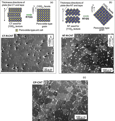
Ruddlesden–Popper-type Ca3Ti2O7 (CT) is an isomorph of Sr3Ti2O7 which was synthesized in a plate-like shape by a molten salt synthesis (MSS) and used as a template for {100}pc-textured regular perovskite-type ceramics [Citation11, Citation20]. Ruddlesden–Popper-type layered perovskite has an interlayer parallel to orthorhombic {010}, i.e., {100}pc for a perovskite unit cell, where the periodic bond chain (PBC),-Ti–O–Ti–O-,is terminated with a corner of TiO6 octahedron. The equilibrium shape of a crystal in this family would be plate-like with its interlayer as a developed plane [Citation9]. Thus the plate-like CT particles, if aligned with the developed plane parallel to one another, could be converted topochemically into the regular perovskite with its {100}pc parallel to the original interlayer of the reactive template, schematically described in figure (a) [Citation21].
Figure 1. Crystal structures of (a) (100)-type layered perovskite Ca3Ti2O7, and (b) (110)-type layered perovskite Nd2Ti2O7, schematically shown with crystal structures of distorted regular perovskite (Ca0.7Nd0.3)0.87TiO3 with their TiO6 octahedrons approximately aligned in the same directions as the layered perovskite reactive templates.
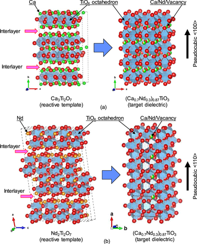
On the other hand, Nd2Ti2O7 (NT) has a strontium pyroniobate (Sr2Nb2O7)-type structure which has an interlayer parallel to {110}pc for a perovskite unit cell, where the PBC is terminated with a edge of TiO6 octahedron. Brahmaroutu et al reported that Sr2Nb2O7 particles prepared by MSS exhibited elongated plate-like morphology [Citation22]. Plate-like Sr2Nb2O7 particles were reported to be used as reactive templates for regular perovskite-type ceramics with a preferred {110}pc [Citation23]. If NT particles also show plate-like morphology similarly to its isomorphic compound, they are also expected to be converted topochemically into a regular perovskite with its {110}pc parallel to the original interlayer of the reactive template, schematically described in figure (b) [Citation21].
As complementary reactants for the formation of CNT, Nd-and Ti-source materials must be mixed with CT platelets for the {100}pc texture, whereas Ca-and Ti-source materials are needed with NT platelets for the {110}pc texture. Three types of reaction schemes were designed with the use of reactive templates (denoted as ‘|rt’):1
2
3
The reaction schemes (Equation11 ) and (Equation2
2 ) were designed so that the complementary reactants for A-site and B-site are supplied separately. The reaction scheme (Equation3
3 ) was designed, to the contrary, with the use of maximum amount of complex oxide and minimum amount of simple oxide/carbonate, for the preparation of dense ceramics with minimized formation of Kirkendall voids. In the reaction (Equation1
1 ), 40.6% of titanium is supplied by the reactive template CT, whereas 26.1% of titanium is given by the reactive template NT for the reaction (Equation2
2 ) and (Equation3
3 ).
3. Experimental procedures
3.1. Preparation of reactive template particles
Two types of plate-like reactive template particles were prepared by MSS in a mixed KCl + NaCl flux. CaCO3 (Kojundo Chemical Lab., 99% up) and TiO2 (Ishihara Sangyo, Tipaque A-100, anatase, 100 nm, 99% up) were mixed with a Ca/Ti ratio of 3/2 in ethanol by ball milling for Ruddlesden–Popper-type CT. Dried powders were then mixed with the equal weight of 0.5 NaCl + 0.5 KCl as a flux and heat-treated in a platinum crucible at 1673 K for 8 h. Nd2O3 (Kojundo Chemical Lab., 99.9%) and TiO2 were mixed with an Nd/Ti ratio of 1/1 in ethanol by ball milling for strontium-pyroniobate-type NT. Dried powders were similarly mixed with the 0.5 NaCl + 0.5 KCl flux and heat-treated in a platinum crucible at 1573 K for 8 h. Products were immersed in deionized water at 353 K and the flux was removed by repeated filtration until chlorine could not be detected by AgNO3 solution. Equiaxed CT and NT particles were also prepared as reference specimens by solid-state reactions (SSRs) of CaCO3 and TiO2, and Nd2O3 and TiO2, respectively, without flux.
3.2. Preparation and characterization of textured CNT polycrystals
Table lists the source materials and compositions used for the preparation of CNT ceramics. Conventionally processed CNT ceramics (CP-CNT) were prepared by sintering of CNT powder compacts synthesized by an SSR. The SSR–CNT powder was prepared by heating mixed powder compacts of CaCO3, Nd2O3 and TiO2 with a stoichiometric ratio (Ca:Nd:Ti = 0.609:0.261:1) at 1473 K for 8 h and pulverized by ball-milling. Die-pressed (at 25 MPa) and cold-isostatic-pressed (at 300 MPa) SSR–CNT powder compacts were sintered at 1673–1823 K for 10 h in air for the preparation of CP-CNT with different grain sizes.
Table 1. Molar ratios of materials used for four batches of (Ca0.7Nd0.3)0.87TiO3 ceramics.
For textured CNT, three batches of slurries were prepared by mixing molten-salt-synthesized plate-like particles with complementary reactants as well as polyvinyl butyral (PVB) as a binder and di-n-butyl phthalate (DBP) as a plasticizer dissolved in a mixed toluene–ethanol solvent. Plate-like calcium titanate, MSS–CT, identified as a mixture of Ca3Ti2O7 and Ca4Ti3O10 particles, was used as a reactive template while Nd2O3 and TiO2 were used as complementary reactants for CT–R–CNT. Here ‘R’ stands for a specimen prepared with ‘raw material-type’ complementary reactant(s). A Ca/Ti ratio of 1.35, determined by inductively coupled plasma atomic emission spectrometry (ICP-AES) analysis, was used for the MSS–CT for the calculation of starting powder ratio. Plate-like Nd2Ti2O7 particles, MSS–NT, were used as a reactive template for NT–R–CNT and NT–F–CNT where ‘F’ stands for a specimen prepared with ‘filler-type’ complementary reactant(s). As complementary reactants, CaCO3 and TiO2 were used for NT–R–CNT whereas pre-synthesized equiaxed CaTiO3 powder by a SSR (heated at 1473 K for 8 h in air and pulverized by ball-milling) was used with TiO2 for NT–F–CNT. The slurries were tape-cast by a doctor blade technique into ∼0.1 mm thick tapes and the tapes were stacked at 353 K at 10 MPa into 1 mm thick green bodies. The alignment of the developed planes of the reactive template particles was confirmed by x-ray diffraction (XRD) for the tape-casting surfaces of the green bodies. The green bodies were dewaxed at 873 K for 2 h and sintered at 1773 K for 10 h in air.
The densities of sintered specimens were evaluated by the Archimedes method and compared with calculated values from lattice parameters which were determined by XRD. Phase development and texture were characterized by XRD for the tape-cast plane after the removal of as-fired surfaces. Texture was evaluated in terms of the Lotgering’s factor, F = (p − p0)/(1 − p0), where p = ΣI(h00)pc/ΣI(hkl)pc for {100}pc-textured ceramics and p = ΣI(hh0)pc/ΣI(hkl)pc for {110}pc-textured ceramics, and p0 = p (F = 0) for randomly oriented ceramics [Citation24]. The perpendicular sections of the sintered specimens to the original tape surfaces were mirror-polished and thermally etched at 1473–1523 K for 30 min in air for the observation of microstructures in terms of grain sizes and morphologies by scanning electron microscopy (SEM). The average grain sizes of the ceramics were estimated by the intercept method.
3.3. Measurements of dielectric properties
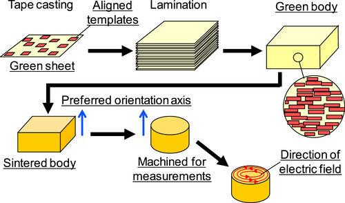
For microwave dielectric measurements, secondary lamination of 1 mm thick green bodies and subsequent sintering produced 10 mm thick specimens for highly textured CNT ceramics as well as randomly oriented CP-CNT ceramics. Cylindrical specimens 8.2 mm in diameter and 4.1 mm in thickness were machined out from the sintered bodies with their cylinder axes perpendicular to the original tape surfaces, as schematically shown in figure . Hakki–Coleman and Kobayashi methods [Citation25, Citation26] were used to determine the microwave dielectric quality factor Q and relative permittivity ∊r in the TE011 mode at frequencies ∼5 GHz with a network analyzer (HP, 8757 A) at 298 K. Temperature coefficient of resonant frequency τf was measured between 298 and 353 K. It should be noted that the electric field is in the circular direction which is parallel to the original tape surfaces and perpendicular to the orientation axis of textured ceramics.
Figure 2. Schematic relationships between tape-cast green sheets and sintered ceramic before and after machining into a cylinder for microwave dielectric measurements.
4. Results and discussion
4.1. Morphologies and phases of flux-grown particles
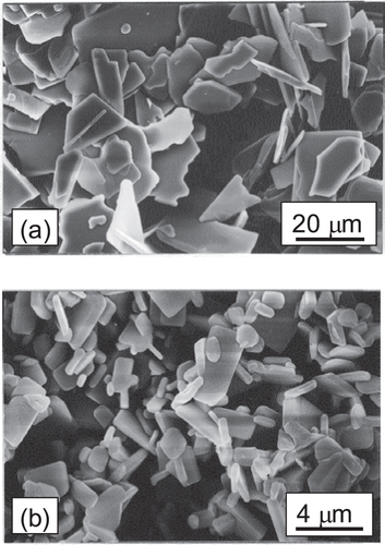
Figure shows SEM images of flux-grown particles. MSS–CT particles show plate-like morphology with disordered shapes in their developed plane with sizes of 10–20 μm. MSS–NT particles show business card-like morphology with their developed plane sizes of 1–5 μm. The aspect ratios of the plate-like particles were approximately ∼20 and ∼10 for MSS–CT and MSS–NT, respectively.
Figure 3. SEM images of flux-grown particles. (a) MSS–CT particles prepared at 1673 K for 8 h. (b) MSS–NT particles prepared 1573 K for 8 h.
XRD analysis showed that MSS–NT was single-phase Nd2Ti2O7, whereas MSS–CT was composed of Ca3Ti2O7 and Ca4Ti3O10, both Ruddlesden–Popper-type-structured compounds with two and three-layers of perovskite units, respectively. Synthesis conditions for single-phase Ca3Ti2O7 were not found in the preliminary MSS experiment, for the MSS–CT products synthesized at 1473 and 1573 K for 8 h were single-phase CaTiO3 and mixed phases of CaTiO3 and Ca4Ti3O10, respectively, whereas a SSR from the same mixed powders of Ca/Ti = 3/2 without flux produced phase-pure Ca3Ti2O7. The Ca/Ti atomic ratio for the MSS–CT particles was determined as 1.35 by ICP-AES and this value was used for the reaction design for RTGG processing as mentioned previously.
4.2. Textures and microstructures of ceramics
Figure shows XRD patterns for the tape casting surfaces of the CT–R–CNT and NT–R–CNT green sheets, as compared with the powder diffraction patterns of equiaxed CT and NT prepared by SSRs. It is apparent that the {010} plane of CT and the {100} plane of NT were aligned parallel to the sheet surfaces by a shear stress during tape-casting. The results indicate that they are developed planes of the plate-like template particles, as expected.
Figure 4. XRD patterns for (a) the green sheet surface of CT–R–CNT as compared with equiaxed Ca3Ti2O7 particles prepared by a solid-state reaction, and (b) the green sheets surfaces of NT–R–CNT and NT–F–CNT as compared with equiaxed Nd2Ti2O7 particles prepared by a solid-state reaction.
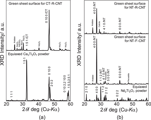
Table lists the relative density, average grain size and Lotgering’s degree of orientation of the sintered specimens. All the sintered ceramics exhibited similar relative densities ranging between 96.8 and 97.8%. The lowest value (96.8%) was measured for NT–R–CNT which used a large amount of CaCO3 as a Ca source. Instead, NT–F–CNT with the use of pre-synthesized perovskite CaTiO3 as a Ca source exhibited improved density (97.6%) as designed.
Table 2. Relative density, grain size and Lotgering’s orientation degree F of (Ca0.7Nd0.3)0.87TiO3 ceramics.
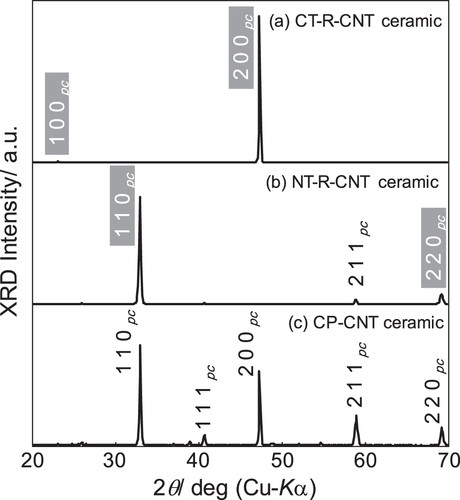
Figure shows XRD patterns for the sintered ceramics of CT–R–CNT and NT–R–CNT on the polished surfaces parallel to the original tape surfaces as well as an XRD pattern for the conventionally processed CP-CNT ceramic. It should be noted that (100)pc and (110)pc corresponds to (101) and (020), and (200) and (121), respectively, in orthorhombic notation. All the sintered specimens are single-phase distorted and A-site deficient regular-perovskite CNT. It is remarkable that CT–R–CNT exhibits strong {100}pc-family XRD peaks whereas NT–R–CNT is highly {110}pc-textured, with the other diffraction peaks were drastically suppressed.
Figure 5. XRD patterns for the RTGG-processed ceramics of (a) CT–R–CNT and (b) NT–R–CNT on the polished surfaces parallel to the original tape surfaces as well as XRD pattern for (c) the conventionally processed CP-CNT ceramic. All the ceramics were sintered at 1773 K.
The textured ceramics display unique microstructures on the sections perpendicular to the original tape surfaces when compared with a microstructure of conventionally processed CP-CNT with random orientation (figure (c)). The {100}pc-textured CNT ceramic shows a microstructure with parallel aligned block-shaped grains, or a brick-wall-like structure (figure (a)), whereas the {110}pc-textured CNT ceramic displays ∼45° obliquely aligned block-shaped grains, like a stone-wall structure often seen in Shinto shrines (figure (b)). These unique microstructures are the results of in situ topochemical formation of a distorted perovskite from layered perovskite templates with the orientation of TiO6 octahedrons preserved, and the successive templated growth of the oriented large-sized grains at the expense of small randomly oriented grains formed between reactive templates. A regular perovskite-type structured grains such as relaxer-PbTiO3 generally grows with pseudocubic {100} facets [Citation27], for the 〈100〉pc is the slowest growth direction and the {100}pc is the plane with the lowest surface energy and its charge balanced. Similar brick-layer-like microstructure was reported for a {100}pc-textured piezoelectric K0.5Na0.5NbO3-based ceramic by Saito et al [Citation8]. Templated grains of CNT also grow in an idiomorphic shape with pseudocubic {100} facets, leading to the unique microstructures, as schematically included in figure . It should be noted that the horizontal grain size of the {100}pc-textured CNT is only a little larger than the diameter of the original CT template while an exaggerated grain growth occurred in the {110}pc-textured CNT. The former result suggested that the grain size could be controlled for {100}pc-textured perovskite-type ceramics by the size and amount of template particles in the RTGG processing because the templated grains with 〈100〉pc orientation grow with {100}pc facets, meet each other and stop the growth with similar surface energy conditions. We assume an ideal situation: perfect uniaxial alignment and random in-plane orientation of template-originated grains. In a {100}pc-textured perovskite, meeting of vertically growing grains with {100}pc facets parallel to each other would form a {100}pc grain boundary for both grains with no further growth. Meeting of horizontally growing grains with {100}pc facets with an arbitrary angle would form a thermodynamically stable grain boundary such as a twin boundary. For a {110}pc-textured perovskite, on the other hand, such simple meetings of two {100}pc facets rarely occur, resulting in the significant grain growth at the expense of other template-originated grains.
Figure 6. SEM images of (a) {100}pc-textured CT–R–CNT and (b) {110}pc-textured NT–R–CNT ceramics for the polished and thermally etched sections that were perpendicular to the original tape surfaces as well as (c) conventionally processed CP-CNT ceramic, sintered at the same temperature. Schematic diagrams for the formation of aligned grains with {100}pc facets are also displayed.
The NT–F–CNT ceramic exhibited, however, only a weak {110}pc texture. It is attributed to the introduction of pre-synthesized perovskite CaTiO3. Regular perovskite phase is thermodynamically more stable than layered perovskite in general and thus diffusion-out of Nd from Nd2Ti2O7 templates for CaTiO3 particles was possibly promoted rather than diffusion-in of Ca from CaTiO3 into Nd2Ti2O7 templates, which is required for the grain growth of reactive templates.
4.3. Microwave dielectric properties of ceramics
Table lists ∊r and Q · f values for the textured and non-textured CNT ceramics. All the ceramics exhibited nearly identical relative permittivity ranging 99–102, which has a good agreement with the value (∼108) of conventionally processed Ca0.61Nd0.26TiO3 ceramics reported by Liang et al [Citation28]. Similar τf values (∼225 ppm K−1) regardless of the processing routes assure the similar composition of the three specimens sintered at 1773 K. Origins of a microwave dielectric loss are generally considered as; (1) material itself, (2) crystalline defects, and (3) microstructure of a ceramic including pores and grain boundaries. Microwave dielectric loss in ceramics generally increases as the porosity increases or the grain size decreases. The Q · f values for the conventionally processed CNT ceramics, CP-CNT, increased as the sintering temperature increased. It is because the ceramics sintered at higher temperature have larger grain size and thus fewer grain boundaries, which resulted in reduced scattering of electric field. Apparent dependence of the Q · f value on the grain size for the CP-CNT ceramics, as plotted in figure , reveals that the grain boundary scattering is the major determining factor for the dielectric loss in this series of CNT ceramics because they have similar relative densities and compositions but different microstructures.
Table 3. Dielectric properties of CNT ceramics.
Figure 7. The Q · f values for textured (red square and triangle) and non-textured (blue circles) CNT ceramics as a function of average grain size.
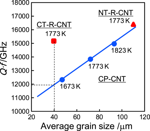
The {100}pc- and {110}pc-textured CNT ceramics exhibited ∼10 and ∼20% higher Q · f values, respectively, than the conventionally processed specimen at the same sintering temperature (1773 K). The high Q · f value for the {110}pc-textured CNT can be attributed to the large grain size as shown in figure although even higher property is expected if the density is identical to the non-textured. It is obvious, however, that the {100}pc-textured CNT ceramic exhibited 27% larger figure of merit than non-textured with the same grain size on the extrapolated line. Although the electric field and orientation axis were not in the same direction, three-dimensional randomness were reduced to two-dimensional randomness along the electric field in the textured CNT ceramics. Especially for the {100}pc-textured CNT ceramic, grain boundaries are, ideally, either perpendicular or parallel to the cylindrical axis of the ceramic specimen. In other words, electric field mostly penetrates {hk0}pc-type grain boundary planes which are parallel to the cylindrical axis. Simpler geometrical relationships between grains in the {100}pc-textured CNT ceramic could also lead to reduced residual stresses and reduced scattering at grain boundaries along the electric field than in the randomly oriented polycrystals. Compared with the {100}pc-texture, {110}pc-textured ceramic must have more randomly oriented grain boundary distribution along the electric field.
5. Conclusions
This paper exhibits texture design and fabrication of bulk ceramics with two different pseudocubic preferred orientation directions. Texture-dependent microwave dielectric characteristic was also suggested in this study with an improved figure of merit for the {100}pc-textured ceramic when compared with randomly oriented. It should be emphasized that the design and fabrication of favorable grain boundary orientation would be a key for microwave dielectric ceramics whereas crystallographic orientation is important for piezoelectric ceramics. Grain boundary orientation is also significantly important for ceramics with electrical conductivity [Citation29]. Advancement in RTGG method would give ceramic engineers more freedom in design and fabrication of high performance devices regardless of the availability of a bulk single crystal with a desired composition. ‘Texture engineering’ for regular perovskite-type materials could enable polycrystalline ceramics with tailored grain and boundary orientations, leading to unique and enhanced properties for various functional devices.
Acknowledgments
The authors would like to thank Professor Mehmet A Gülgün of Sabanci University and Professor Toshio Kimura of Keio University for their invaluable discussions on this paper. Many helpful suggestions from Drs Kazumasa Takatori, Yasuyoshi Saito, Kensuke Wada and Mr Akitoshi Suzumura of Toyota CRDL are also gratefully acknowledged.
References
- TakenakaTSakataK 1980 Grain-orientation and electrical-properties of hot-forged Bi4Ti3O12 ceramics Japan. J. Appl. Phys. 19 31 39 31–9 10.1143/JJAP.19.31
- SuzukiTSakkaYKitazawaK 2001 Orientation amplification of alumina by colloidal filtration in a strong magnetic field and sintering Adv. Eng. Mater. 3 490 492 490–2 10.1002/1527-2648(200107)3:7<490::AID-ADEM490>3.0.CO;2-O
- MakiyaAKusanoDTanakaSUchidaNUematsuKKimuraTKitazawaKDoshidaY 2003 Particle oriented bismuth titanate ceramics made in high magnetic field J. Ceram. Soc. Japan 111 702 704 702–4 10.2109/jcersj.111.702
- HiraoKOhashiMBritoM EKanzakiS 1995 Processing strategy for producing highly anisotropic silicon-nitride J. Am. Ceram. Soc. 78 1687 1690 1687–90 10.1111/j.1151-2916.1995.tb08871.x
- HornJ AZhangS CSelvarajUMessingG LTrolier-McKinstryS 1999 Templated grain growth of textured bismuth titanate J. Am. Ceram. Soc. 82 921 926 921–6 10.1111/j.1151-2916.1999.tb01854.x
- TaniT 1998 Crystalline-oriented piezoelectric bulk ceramics with a perovskite-type structure J. Korean Phys. Soc. 32 S1217 S1220 S1217–20
- SabolskyE MJamesA RKwonSTrolier-McKinstrySMessingG L 2001 Piezoelectric properties of 〈001〉 textured Pb (Mg1/3Nb2/3) O-3-PbTiO3 ceramics Appl. Phys. Lett. 78 2551 2553 2551–3 10.1063/1.1367291
- SaitoYTakaoHTaniTNonoyamaTTakatoriKHommaTNagayaTNakamuraM 2004 Lead-free piezoceramics Nature 432 84 87 84–7 10.1038/nature03028
- WatariKBrahmaroutuBMessingG LTrolier-McKinstrySChengS C 2000 Epitaxial growth of anisotropically shaped, single-crystal particles of cubic SrTiO3 J. Mater. Res. 15 846 849 846–9 10.1557/JMR.2000.0121
- FukuchiEKimuraTTaniTTakeuchTSaitoY 2002 Effect of potassium concentration on the grain orientation in bismuth sodium potassium titanate J. Am. Ceram. Soc. 85 1461 1466 1461–6 10.1111/j.1151-2916.2002.tb00297.x
- TakeuchiTTaniT 2002 Texture development of SrTiO3 ceramics during reactive templated grain growth processing J. Ceram. Soc. Japan 110 232 236 232–6 10.2109/jcersj.110.232
- SugawaraTNomuraYKimuraTTaniT 2001 Fabrication of (111) oriented BaTiO3 bulk ceramic by reactive templated grain growth method J. Ceram. Soc. Japan 109 897 900 897–900 10.2109/jcersj.109.1274_897
- TaniTLiJ FViehlandDPayneD A 1994 Antiferroelectric–ferroelectric switching and induced strains for sol–gel derived lead zirconate thin-layers J. Appl. Phys. 75 3017 3023 3017–23 10.1063/1.356146
- IijimaTItoSMatsudaHTaniMAkamatsuMYasudaY 2003 Transducing Materials and Devices Bar-CohenY Bellingham, WA SPIE 98 110 pp 98–110
- WadaKFukamiYKakimotoKOhsatoH 2005 Microwave dielectric properties of textured BaLa4Ti4O15 ceramics with layered perovskite structure Japan. J. Appl. Phys. 1 44 7094 7097 7094–7 10.1143/JJAP.44.7094
- SaitoYTakaoHWadaK 2008 Synthesis of platelike CaTiO3 particles by a topochemical microcrystal conversion method and fabrication of textured microwave dielectric ceramics Ceram. Int. 34 745 751 745–51 10.1016/j.ceramint.2007.09.017
- TakeuchiTTaniT 1999 Texture engineering of perovskite-type bulk ceramics Abstract Book of the 101st Annual Meeting and Exposition of the American Ceramics Society Indianapolis, IN 25–28 April p 347
- YoshidaMHaraNTakadaTSekiA 1997 Structure and dielectric properties of (Ca1−xNd2x/3) TiO3 Japan. J. Appl. Phys. 1 36 6818 6823 6818–23 10.1143/JJAP.36.6818
- Zhang Q-lS H-PYangH 2011 Low-temperature sintering and dielectric properties of high-permittivity microwave (Ca, Nd) TiO3 ceramics J. Alloys Compd. 509 9986 9991 9986–91 10.1016/j.jallcom.2011.08.005
- TakeuchiTTaniTSatohT 1998 Microcomposite particles Sr3Ti2O7–SrTiO3 with an epitaxial coreshell structure Solid State Ion. 108 67 71 67–71 10.1016/S0167-2738(98)00020-4
- MommaKIzumiF 2011 VESTA 3 for three-dimensional visualization of crystal, volumetric and morphology data J. Appl. Crystallogr. 44 1272 1276 1272–6 10.1107/S0021889811038970
- BrahmaroutuBMessingG LTrolier-McKinstryS 1999 Molten salt synthesis of anisotropic Sr2Nb2O7 particles J. Am. Ceram. Soc. 82 1565 1568 1565–8 10.1111/j.1151-2916.1999.tb01956.x
- TakeuchiTTaniT 2002 Electroceramics in Japan IV MurataM Zurich-Uetikon Trans Tech Publications 3 6 pp 3–6
- LotgeringK 1959 Topotactical reactions with ferrimagnetic oxides having hexagonal crystal structures—I J. Inorg. Nucl. Chem. 9 113 123 113–23 10.1016/0022-1902(59)80070-1
- HakkiB WColemanP D 1960 A dielectric resonator method of measuring inductive capacities in the millimeter range Inst. Radio Eng. Trans. Microw. Theory Tech. MTT-8 402 410 402–10 10.1109/TMTT.1960.1124749
- KobayashiYTanakaS 1980 Resonant modes of a dielectric rod resonator short—circuited at both ends by parallel conducting plates IEEE Trans. Microw. Theory Tech. 28 1077 1085 1077–85 10.1109/TMTT.1980.1130228
- LiTScotchA MChanH MHarmerM PParkS EShroutT RMichaelJ R 1998 Single crystals of Pb (Mg1/3Nb2/3) O-3-35 mol% PbTiO3 from polycrystalline precursors J. Am. Ceram. Soc. 81 244 248 244–8 10.1111/j.1151-2916.1998.tb02325.x
- LiangB LZhengX HTangD P 2009 New high-epsilon and high-Q microwave dielectric ceramics: (1−x) Ca0.61Nd0.26TiO3−xNd (Zn0.5Ti0.5) O3 J. Alloys Compd. 488 409 413 409–13 10.1016/j.jallcom.2009.09.001
- ItaharaHSugiyamaJTaniT 2004 Enhancement of electrical conductivity in thermoelectric [Ca2CoO3] 0.62 [CoO2] ceramics by texture improvement Japan. J. Appl. Phys. 1 43 5134 5139 5134–9 10.1143/JJAP.43.5134