Abstract
The machinability of various grades of austempered ductile iron (ADI) has been investigated for rough milling operations. ADI 900, ADI 1050 and ADI 1200 grades were commercially produced, commercially heat treated and machined under controlled conditions using coated carbide inserts with coolant in the laboratory. The milling performance of the various grades was compared to that of AISI/SAE 4340 with similar hardness. In this study, machinability characteristics relative to wear rate (ISO 8688-2) and machining forces were measured and related to initial microstructure and properties. These preliminary results have been used to establish initial rough milling machining guidelines for machining ADI with coated carbide milling inserts.
Introduction
Improving the machinability of austempered ductile irons (ADIs) after heat treatment is a key driver for the further development and use of ADI. The unique ausferrite matrix structure in ADI provides strength and toughness levels that cannot be achieved with the conventional grades of ductile iron. This permits designers to substitute ADI for high performance ferrous and non-ferrous materials in a wide variety of engineering applications. However, the strength and hardness of the ausferrite matrix in ADI present machining challenges that must be overcome for cost effective material substitution to ADI.
Comprehensive machining guidelines have been established for the conventional grades of ductile irons, but not for the various grades of ADI. The excellent machinability of conventional ductile irons can be attributed in part to the graphite nodules present in the matrix that contribute to lower cutting forces, increase tool life and effectively manage chip formation compared to steels of similar hardness levels. These graphite nodules play a similar role in the machining of ADI. However, the ‘ausferrite’ ADI matrix is significantly harder than the ferrite/pearlite matrices of the conventional ductile iron. In addition, the austenite fraction of the ausferrite matrix surrounding the graphite nodules in ADI not only work harden significantly but can, if unstable, transform to hard martensite ahead of and beneath the cutting tool due to the high localised plastic strains associated with machining operations.
During the past 25 years, researchers have studied the machinability of ADI, but most of these studies have reported only on tool wear or cutting forces in dry turning that are not characteristic of the production machining of ADI. In many cases, more limited production machining studies, such as the early work of SheaCitation1 and recent studies by Zanardi,Citation2 are not reported in detail and cannot be effectively used to develop more comprehensive ADI machining guidelines. At present time, the ADI machining recommendations published by the Ductile Iron Society, based primarily on anecdotal data rather than comprehensive machining studies, may provide minimal guidance for initial machining parameters for the low strength grades of ADI.Citation3 Other researchers have studied the machining response of the various grades of ADI and the mechanisms of chip formation and tool wear that limit machinability. Notable are the detailed studies by Klocke and co-workersCitation4,Citation5 and by Polishetty,Citation6 describing in detail the microstructural response of the ausferrite and its interaction with the cutting tool during machining. When these studies are evaluated as a whole, much variation has been observed in machining performance of ADI, particularly for the lower strength ADI 900 grade. This grade of ADI has the largest amount of stabilised austenite present in the matrix structure and the smallest austempering heat treatment process window. Insufficient austempering times do not fully stabilise the austentise, causing it to transform to martensite upon cooling, while excessive austempering results in stage II decomposition of the austenite to ferrite and carbide with an associated decrease in toughness.Citation7
Selected studies have examined the milling behaviour of ADI,Citation1,Citation2, but none of these past studies have resulted in useful guidelines that can be used to establish helpful initial machining conditions for face milling or end milling of the various grades of ADI.
Material characterisation
This machinability investigation evaluated three of six ASTM grades of ADI: ADI 900, ADI 1050 and ADI 1200. Chemical composition of conventional ductile iron used to produce these ADI grades is shown in . The number and shape of the graphite nodules are important in ductile iron production. The ductile iron components had nodule count of 326 nodules mm− 2 and nodularity of 93%. Ductile iron components were austenised at the same temperature and time but quenched and held at different austempering temperature and time treatments for different ADI grades. Austenising on ductile iron components was performed at 885°C for 128 min. Different austempering temperatures and times were controlled to produce ADI 900, ADI 1050 and ADI 1200. The different austempering temperatures and times influence the ausferrite structure and, thus, the mechanical properties of ADI. ADI 900, which was austempered at higher temperature, has more stabilised austenite within the ausferrite matrix compared to ADI 1050 or ADI 1200 based on X-ray diffraction analysis. The photographs of etched ADI 900, ADI 1500 and ADI 1200 along with their matrix characteristics and hardness are shown in . The hardness for all grades was in the middle of the respective allowable hardness range.
Table 1 Chemical composition of ductile iron used to produce ADI
Table 2 Microstructure after austempering heat treatment
In order to further evaluate the machinability of ADI, a widely used conventional material with similar properties and applications was also evaluated. AISI/SAE 4340 is used in a wide range of applications because of its high hardenability combined with great ductility, toughness and strength. The high strength/weight ratio and wear resistance properties of ADI might allow this material to outperform AISI/SAE 4340 in many applications. AISI/SAE 4340 also exhibits relatively poor machinability with machinability ratings of 55% for cold drawn material and 45% for annealed material based on 100% machinability of cold rolled B1112.Citation6 Investigating the machinability of AISI/SAE 4340 and ADI in tandem provided a means of evaluating the validity of ADI as an alternative to AISI/SAE 4340. The hardness of AISI/SAE 4340 was found to be 351 HBW, which was between that of ADI 900 and ADI 1050. It should be noted that the bulk hardness of ADI is typically 20–40 Brinell hardness points less than the hardness of the ADI matrix itself because of the presence of the soft graphite nodules.
Experimental
This study was performed to investigate how different material characteristics (microstructure and hardness) of ADI 900, ADI 1050 and ADI 1200 affect the milling performance. A series of end milling and face milling experiments were conducted to evaluate the machinability of ADI in comparison to AISI/SAE 4340. The effects of chip load on cutting force and cutting stiffness of the materials were investigated using end milling experiments. Face milling experiments were performed to observe the effects of cutting speed on the tool life. The casting scale was removed before testing and workpieces were cut into 101 × 76 × 25 mm for end milling and 305 × 151 × 25 mm for face milling.
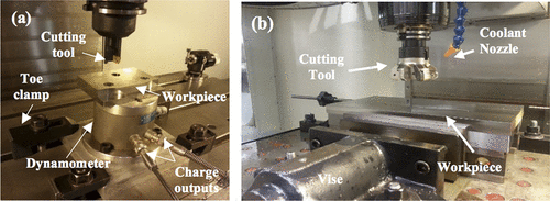
The end milling experiments were carried out on a HAAS VF-2SS using a dynamometer mounted to the machining centre table. The set-up for the end milling operations is shown in . The axes of the dynamometer and machining centre were aligned, which effectively aligned Fx and Fy with the machine feed directions. To minimise dynamometer charge drift, the charge amplifiers were in the reset position until data collection started, and a long time constant was used. Data were collected using a data acquisition system (NI cDAQ-9178) through a LabVIEW user interface. The tool used was a Kennametal 1023642 indexable square shoulder end mill tool holder (19 mm diameter) with a Kennametal SDEB080201 KC725M carbide coated insert [TiAlN-physical vapour deposition (PVD) coated] which has 0° rake, 15° relief and nose radius of 0.1 mm. A single insert configuration was used to collect the cutting force data.
The end milling experiments were conducted to determine machinability metrics related to cutting force (e.g. cutting stiffness). A Matlab subroutine was coded to compute instantaneous values of chip thickness, cutting stiffness and beta angle based on the procedure described by Stephenson and Agapiou. Hardness values of the work materials were used to establish test conditions for the initial cutting force experiments (from Machining Data Handbook). In these cutting tests, the chip load was varied between 0.05 and 0.15 mm/tooth to determine any dependence of cutting stiffness on chip load. The cutting speed and depth of cut were held constant at 15 m min− 1 and 1 mm respectively, and 20% radial immersion was used.
The face milling experiments were carried out on a Haas VF-2 vertical CNC Mill with the use of a large modular vise. The set-up for the face milling operations is shown in . A Seco Double Octomill 220.48-09S R220.48-03.00-09-06SA (diameter 80 mm) was used in a three-insert configuration (equal angular spacing) with a radial immersion of 63%. The tool holder had axial and radial rake angles of − 8°, a cutting rake angle of − 11° and a tool cutting edge angle of 40°. Additionally, due to the cutting insert geometry, an effective relief angle of 15° was used. The cutting tool tested was a Seco coated carbide insert (ONMU090520ANTN-M14 MK2050) with physical vapour deposition deposited TiSiN–TiAlN nanolaminate coating. The coolant used to reduce the tool–workpiece interfacial temperature was Quakercool 7020-CG (Quaker Chemical Company) at coolant concentration between 7 and 8%, which was verified using a Westover Portable Refactometer, model RHB-32, and titration.
The tool life experiments were conducted according to ISO 8688-2. Five cutting speed configurations were investigated per work material with three replications per condition. Useful tool life was defined as maximum flank wear penetration VBmax measured from the uniform wear of 0.3 mm (average wear across all teeth) or localised wear of 0.5 mm (on any individual tooth). Wear land measurements were taken over intervals corresponding to constant volume of material removed (e.g. after each pass). Preliminary experiments indicated that the different grades of ADI required different cutting speeds due to the hardness variation across the set of work materials. The ADI 900, ADI 1050 and ADI 1200 were tested at speed of 240 to 480 m min− 1, 240 to 480 m min− 1 and 120 to 360 m min− 1 respectively. The AISI/SAE 4340 tests were limited to cutting speed of 240, 360 and 480 m min− 1. Chip load and depth of cut were held constant at 0.08 mm/tooth and 1 mm respectively.
Results and discussion
Cutting forces
The comparison of force traces for a single cutting event (Fx, Fy, F) for ADI and AISI/SAE 4340 at a chip load of 0.15 mm/tooth is shown in . Cutting forces increased steadily as the tool rotated and fell to zero when exiting the workpiece. Oscillation in the force trace at exit was due to system compliance. Furthermore, a general increasing in the resultant cutting force was observed as the chip load increased for all grades of ADI and AISI/SAE 4340. ADI 1050 exhibited the largest resultant cutting forces of the ADI grades, ranging from 188 to 435 N, while ADI 900 had the smallest forces, ranging from 169 to 399 N. The resultant cutting force of ADI 1200 exceeded that of ADI 1050 only for chip load of 0.13 mm/tooth. AISI/SAE 4340 exhibited a slightly higher resultant cutting force than the ADI grades at lower chip loads up to 0.08 mm/tooth, but was similar to that of ADI 900 at higher chip loads. Although trends were observed, the difference of the resultant cutting force between materials was still within ± 1σ.
2 a results for collected cutting forces Fx and Fy and calculated resultant cutting force F for the grades of ADI: (i) ADI 900, (ii) ADI 1050, (iii) ADI 1200 and (iv) AISI/SAE 4340 (a = 1 mm, f = 0.15 mm/tooth, SS = 252.5 rev min− 1 and 20% radial emersion); b effect of chip load on cutting stiffness
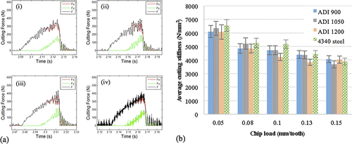
In contrast to cutting force, cutting stiffness exhibited a decreasing trend as chip load increased, as shown in . The cutting stiffness values for ADI 1200, ADI 1050 and ADI 900 ranged from 4060 to 6094 N mm− 2, 3677 to 6344 N mm− 2 and 3829 to 6061 N mm− 2 respectively as the chip load decreased. Cutting stiffness for AISI/SAE 4340 ranged from 3888 to 6551 N mm− 2 as the chip load decreased. From this result, there was no significant difference of the cutting stiffness between different materials. However, it is interesting to note the cutting stiffness of the ADI grades fell outside the expected cast iron range (1000 to 1500 N mm− 2) and were within the hardened steel range (2500 to 5000 N mm− 2), similar to AISI/SAE 4340. The similar cutting stiffness between ADI and AISI/SAE 4340 might be attributed to the similarity in hardness, as cutting stiffness is proportional to hardness. However, this cutting stiffness was higher than the cutting stiffness reported by De Carvalho et al.Citation9 Cutting stiffness of 1175–1448 N mm− 2 for ADI 900 and 1236–1501 N mm− 2 for ADI 1050 were observed in a turning study investigating the effect of chip load (0.05–0.4 mm/tooth) on cutting stiffness at different depths of cut (2–5 mm) and cutting speed of 80 m min− 1 with no coolant.Citation10 Note that Kienzle's method for modelling the cutting force with respect to cutting stiffness, chip thickness and chip width was used to calculate the cutting stiffness from the measured cutting forces in these cases.Citation8 Additionally, a wider range of chip loads were studied and resulted in fundamentally different response. Therefore, disparity between the cutting stiffness values can be attributed to the machining configuration and the chip loads investigated.
Tool life
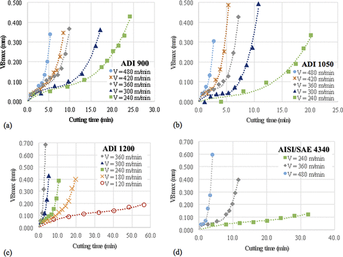
Average tool wear was measured in cutting length intervals of 304.8 mm. Useful tool life was defined as maximum flank wear penetration VBmax by uniform wear of 0.3 mm (average wear across all teeth) or localised wear of 0.5 mm (on any individual tooth). In some cases, tool life was limited by the occurrence of catastrophic tool failure, rather than progressive tool wear. Catastrophic tool failure occurred several times at the lower cutting speeds when machining ADI 900 and ADI 1200. In all other test conditions, stable progressive tool wear was observed.
Typical tool wear profiles were observed when machining ADI across all test conditions. The progressive wear is typically observed at lower cutting speeds. When the cutting speed is fairly low, the cutting edge maintains its proper function at a broader range of cutting time, and the abrasive wear progresses slowly. This continues until a sufficient number of mechanical impact loading cycles occur, resulting in the tool coating being worn away. Abrasive wear then accelerates causing tool failure. It has been reported that the main wear mechanism in dry milling ADI 900 is a combination of abrasive wear and partial destruction of the cutting edge.Citation10 Similarly in this study, milling with cutting fluid, the primary failure modes observed were abrasive wear followed by breakage of the flank. Further, chipping and cracking were shown to occur at all cutting speeds, indicating that the cutting configuration (i.e. climb milling) had a larger influence on wear mode. Discolouration and premature tool breakage also indicate high temperatures at the tool/workpiece interface when aggressively machining ADI. displays a representative of tool wear behaviour as a function of cutting time over a range of cutting speeds. The cutting time was a function of the material removal rate (MRR) and material volume removed (MR), taking into account the effect of cutting speed on the time interval between measurements. Cutting speed expectedly had a major effect on tool wear rate. Higher cutting speeds yielded faster wear rates. When machining ADI 1200, for cutting speeds 180 to 360 m min− 1, wear rate followed mostly uniform and gradual progression of tool wear. However, for a cutting speed of 120 m min− 1, tool wear did not reach steady state before catastrophic tool failure. The tool wear progressions for ADI 1050, ADI 900, and AISI/SAE 4340 followed the expected behaviour for most cost effective machining operations. A rapid increase in the wear rate was observed at the beginning of cutting, which is then followed by a steady state condition and another rapid wear rate towards the end. When machining AISI/SAE 4340 at a cutting speed of 240 m min− 1, the experiment was terminated earlier due to minimal tool wear of 0.124 mm after over 30 min of machining.
3 a ADI 900; b ADI 1050; c ADI 1200; d AISI/SAE 4340
Effect of cutting time on VB for work materials at various cutting speeds
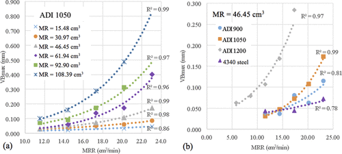
displays tool wear as a function of MRR for given total volume removed for ADI 1050. As expected, the sensitivity of tool wear to changes in MRR increased with increasing in total MR. At smaller total volume of material removed (MR = [15.48, 30.97 cm3]), only small increases in tool wear was observed with increasing MRR. However, the tool wear increased rapidly as MRR increased at greater total material removed (MR = [46.45 to 108.39 cm3]). The comparison of the effect of MRR on tool wear between different materials at constant total material removed of 46.45 cm3 is shown in . ADI 900, ADI 1050 and AISI/SAE 4340 exhibited similar tool wear response at MRR between 11.53 and 17.30 cm3. However, at higher MRR, tool wear was least for AISI/SAE 4340, followed by ADI 900 and ADI 1050. ADI 1200 exhibited much greater tool wear compared to ADI 1050, ADI 900 and AISI/SAE 4340. However, note that the rate of tool wear increase with MRR in ADI 1200 is similar to increasing tool wear in ADI 1050.
4 a example of tool wear sensitivity to MRR for different MR for ADI 1050; b effect of MRR on tool wear for different materials
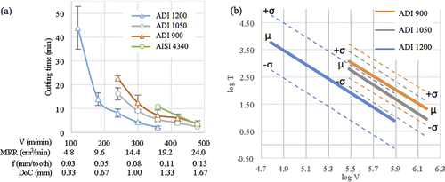
Estimated tool life shown in was extracted from the tool wear progressions by computing the time when the tool reached the established tool wear criterion according to ISO 8688-2. ADI 1200 exhibited tool life ranging from 43.8 to 2.2 min, with rapid decline in tool life from 120 to 180 m min− 1 and more linear degradation with cutting speed from 180 to 360 m min− 1. Tool life for ADI 1050 and ADI 900 gradually decreased from 16.2 to 2.4 min and 22.7 to 3.9 min respectively as cutting speed increased. In addition, for the same cutting speeds, ADI 900 exhibited the best tool life, followed by ADI 1050 and ADI 1200. The tool life for machining AISI/SAE 4340 at 360 and 480 m min− 1 cutting speeds were 10.9 and 3.4 min respectively. The AISI/SAE 4340 outperformed ADI 1050 and ADI 900 at the lower cutting speed (360 m min− 1), but performed similarly to ADI 1050 and ADI 900 at the high cutting speed (480 m min− 1). also displays the expected behaviour of the tool–material combination under several variations of cutting conditions other than cutting speed. Tool life obtained on different cutting conditions (depth of cut and chip load) can be predicted by holding the MRR constant. In , the range of depth of cut and chip load were established using the cutting speed of 300 m min− 1. Further investigation was performed to determine the influence of depth of cut, immersion and chip load on tool life.
The Taylor tool life equation was used to quantify the relationship between cutting speed and tool life and was calibrated for the ADI grades. The tool life tests were used to determine the empirical constants C and n for each ADI grade. In order to derive the constants, the relationship between tool life and cutting speed was plotted on a log–log graph shown in , and models in the form of T = C × V− 1/n were developed for the ADI grades. The solid and dashed lines of represent the mean and standard deviation for each ADI grade respectively. From the linear fit of the data, the constant n was extracted from the slope, while the constant C was extracted from the y intercept of the linear regression. The results of the fit are provided in equation (1) (ADI 900), equation (2) (ADI 1050) and equation (3) (ADI 1200). From these relationships, C varied between 1.2 × 10⁷ and 3.5 × 10⁷, and n varied from 0.381 to 0.397.The Taylor tool life relationshipCitation8 was used to understand the parameters that describe the dependent relationship between cutting speed and useful tool life. The n values, which primarily depend on the tool material, of the three grades were found to be fairly close and indicate mostly constant sensitivity of the tool material to changes in cutting speed. The tool material was most sensitive to cutting speed when machining ADI 900 (n = 0.397) followed by ADI 1200 (n = 0.381) and ADI 1050 (n = 0.376). The tool material (TiSiN–TiAlN nanolaminate coated carbide tool) exhibited n values that fall between TiC and TiN coated uncoated tungsten carbide (WC) tools (n = 0.3) and Al2O3 coated WC tools (n = 0.4).Citation8 In general, it can be assumed that the Seco TiSiN–TiAlN coated carbide tool is less sensitive to cutting speed than TiC or TiN coated WC tools (n = 0.3) and more sensitive than Al2O3 coated WC tools (n = 0.4).Citation8 The constant C is an empirical constant relating the cutting speed and tool life for a particular work and tool material combination.
Katuku and co-workersCitation11 reported an n value of 0.51 and a C value of 3 × 10⁷ for the tool–workpiece combinations of PcBN and ADI 1050 at 0.2 mm depth of cut and 0.05 mm/tooth chip load, with cutting speeds ranging from 50 to 800 m min− 1. Note that the purpose of the study was to investigate the tool–workpiece combination under finishing conditions in dry turning. The n value is mostly based on the tool material, PcBN, indicating lesser sensitivity of tool life to cutting speed in the cutting operation studied. The C value for the tool–workpiece combination of the Seco TiSiN–TiAlN nanolaminate coated carbide tool and ADI 1050 (3.5 × 10⁷) determined in this study was 17% higher than the tool–workpiece combinations of PcBN and ADI 1050 developed by Katuku and co-workers.Citation11 Since similar MRRs were studied, the disparity between C values can be attributed to the tool material.
Conclusions
The machinability of various grades of ADI has been investigated for rough milling operations. ADI 900, ADI 1050 and ADI 1200 grades of material were commercially produced, commercially heat treated and machined under controlled conditions using coated carbide inserts with coolant in the laboratory. The milling performance of the various grades was compared to that of AISI/SAE 4340 with similar hardness. In this study, machinability characteristics relative to wear rate and machining forces were measured and related to initial microstructure and properties. These results help to establish initial rough milling machining guidelines for machining ADI with coated carbide milling inserts.
References
- K. H. W. Seah and S. C. Sharma: “Machinability of alloyed austempered ductile iron,” Int. J. Mach. Tools Manuf., 1995, 35, (10), 1475–1479.
- F. Zanardi: “Fatigue properties and machinability of ADI,” Metall. Ital., 2005, 10.
- K. Brandenberg: “Machining Austempered Ductile Iron (ADI),” Manuf. Eng., 2002, 128, (5), 125–130.
- F. Klocke and D. Lung: “Evaluation of the machining aspects of Austempered Ductile Iron,” Int. J. Met. Cast., 2012, 36–42.
- M. Arft and F. Klocke: “High performance turning of austempered ductile iron (ADI) with adapted cutting inserts,” Proc. CIRP, 2013, 8, 128–133.
- A. Polishetty: ‘Machinability and microstructural studies on phase transformations in Austempered Ductile Iron’, ‘ PhD thesis’; 2012, Auckland, New Zealand, AUT University.
- R. C. Voigt and C. R. Loper: “Austempered ductile iron–process control and quality assurance,” J. Heat Treat., 1984, 3, 291–309.
- D. A. Stephenson and J. S. Agapiou: ‘Metal cutting theory and practice’, 2006, Boca Raton, FL, Taylor & Franics Group, LLC.
- M. V. De Carvalho, D. M. Montenegro and J. D. Gomes: “An analysis of the machinability of ASTM grades 2 and 3 austempered ductile iron,” J. Mater. Process. Technol., 2013, 213, (4), 560–573.
- I. Sadik, K. Hamberg and H. Borgstrom: “The performance of PVD coated grade in milling of ADI 900,” 2010, Proc. CIRP Int. Conf. on ‘High performance cutting’ and ‘The performance of PVD coated grade in milling of ADI 900’, Mar Del Plata, Argentina, Institute for Research in Materials Science and Technology (INTEMA).
- I. Katuku, A. Koursaris and I. Sigalas: “Wear, cutting forces and chip characteristics when dry turning ASTM Grade 2 austempered ductile iron with PcBN cutting tools under finishing conditions,” J. Mater. Process. Technol., 2009, 209, (5), 2412–2420.

