
Abstract
A combination of evanescent wave optical sensors (EWOSs) and fibre Bragg gratings (FBGs) were embedded in an epoxy vinyl ester and an epoxy vinyl ester based glass reinforced polymer (GRP) composite to measure fluid ingress that would result in degradation under hostile conditions. Samples were subjected to accelerated aging in the form of single sided exposure to simulated sea water at 120°C in a pressurised stainless steel vessel. Low cost EWOSs were prepared from a standard multimode glass optical fibre and compared to commercially available FBGs. Both sensors were able to detect the early stage of moisture diffusion into the GRP matrix. The evanescent sensors showed a reduction in the transmitted signal intensity between 1500 and 1650 nm with an increasing exposure time due to a change in the optical properties of the polymer, whereas a peak shift was observed for the FBGs due to the swelling of the resin with the absorption of water. Additionally, the glass optical fibre sensors were embedded in a configuration that allowed the extent of diffusion through the thickness of the GRPs to be monitored, with the fibres in the closest position to the exposure face showing a greater signal change than those positioned further away.
Introduction
Glass reinforced polymer composites (GRPs) are increasingly used in the petrochemical industry; however, there is a reluctance to use them in extreme conditions due to their unknown long term performance. They are cheaper to produce than steel pipes due to the lower processing temperatures and materials costs. They are also cheaper to install as they are lighter and more easily assembled into a pipeline from the component parts.Citation1–Citation3 Composites are effective in providing corrosion protection in significant volumes for industrial processing systems in many different applications. For high risk applications, such as subsea and permanent downhole equipment, the technical challenges are more difficult and the cost of interventions is substantial. For these applications, safe operation relies on the long term stability of a few millimetres of polymer.Citation1
In order to further incorporate GRPs into the petrochemical industry, it is necessary to give accurate, non-invasive data on the degradation rate during the component lifetime of several decades. Smart composite systems, which could monitor the rate of permeation of corrosive media, as well as any degradation through the thickness of GRP, would enable the simulation of the aging process in the laboratory. This would, in turn, enable accurate prediction of the aging behaviour of the material in a service environment after a given number of years. Sensing technologies for the health monitoring of composites, including dielectric spectroscopy using remote sensors,Citation4 fibre optic sensors,Citation5–Citation6 piezoelectric sensorsCitation7–Citation8 and self-diagnosis fibre reinforced composites,Citation9 have great potential for detecting damage via physical and chemical parameters related to the composite health and durability during the service life of structures.
Optical fibre sensors offer several advantages such as operational safety (no moving parts or electrical signals that could potentially cause sparking in a flammable environment) and immunity to electromagnetic interference or ground loops.Citation5 Additionally, they can easily be embedded into composite materials without altering their mechanical performance. The most common fibre optic sensing approaches are those exploiting fibre Bragg gratings (FBGs)Citation10–Citation11 or interferometersCitation12–Citation13 for the measurement of physical quantities (displacements, deformations, accelerations, vibration amplitudes and frequencies). Optical fibre sensors are also emerging as the most suitable solution to detect chemicals.Citation14–Citation16 Many principles have been demonstrated in the literature to sense chemicals using optical fibres, the most common being those based on the interaction with evanescent waves, such as surface plasmon resonance and evanescent wave optical sensors (EWOSs).Citation14,Citation17 Despite using different approaches, both cited techniques are sensitive to the changes in the refractive index due to the molecular interactions that occur within the evanescent field region near the fibre surface, and can be adapted to measure either discreet or cumulative effects. These approaches have been demonstrated using multifunctional fibre optic sensors to obtain real time and in situ information on the crosslinking kinetics, temperature and magnitude of the residual fabrication stresses during GRP manufacturing.Citation18
In this work, a combination of low cost EWOSs, made from a commercially available telecommunications glass fibre, and off the shelf FBGs were embedded in a vinyl ester to monitor the ingress of water through the thickness of GRPs. Monitoring the distribution and level of moisture uptake in polymer composites is essential for determining the long term property retention in aggressive environments.Citation19 Recently, chalcogenide glass optical fibres have been used as fibre evanescent wave spectroscopic sensing elements to monitor the curing process of a thermosetting resin and to track water absorption in an E-glass reinforced polymer composite.Citation9 FBG sensors have already been employed for the detection of moisture diffusion in adhesive joints and bulk polymers by measuring the strain caused by the swelling of the polymeric adhesive.Citation20–Citation21
The main reasons for choosing evanescent sensors were that they are cheap to produce and can be modified to be selective to certain chemicals or groups of chemicals through the use of various coatings on the sensing region.Citation15,Citation22–Citation25 The evanescent field extending from the core of the fibre interacts with the coating or the medium it is immersed in and experiences a change in the transmitted signal. FBGs, on the other hand, are widely used in both research and commercial activities and operate by reflecting specific wavelengths.Citation5,Citation6,Citation10–Citation11,Citation21 The reliable behaviour of the FBGs allowed them to act as an indicator of the performance of the evanescent sensors in this work.
A key aspect of this work was the development of a glass based sensor that could be prepared from widely available commercial materials and treated as disposable. To achieve this, standard telecommunications optical silica fibre that costs less than £300/km was used. This resulted in a cost of around £0.60 per sensor in terms of raw materials and a preparation process that could be scaled up and made autonomous relatively easily.
Experimental
Sample preparation
Optic fibre sensor preparation
The evanescent wave sensors used in this work were prepared from a GIF 625 silica multimode fibre (Thorlabs, Germany). The diameters of the core, cladding and coating were 62.5, 125 and 250 μm respectively. Each fibre was cut to a length of 1 m and had a 6–8 cm sensing region. The sensor was prepared by mechanically stripping 6–8 cm of the coating and then chemically etching the cladding using >40% HF (Sigma-Aldrich) at room temperature for 30 min.
Several sensors were prepared by depositing a copper coating on the bare core by radio frequency magnetron sputtering, from Microcoat S.p.A. A copper target (99.99% purity) from Franco Corradi, Italy, was used. The sputtering deposition parameters were varied in order to optimise the homogeneity of the coating. Ultimately, a power of 300 W, on a 6 inch target, for 2 h was used to obtain Cu coatings with a thickness of ∼6 μm.
The FBG sensors were commercially available gratings (Raysung Photonics Inc., China) inscribed in single mode fibres (Corning 28e); the diameters of the core, cladding and coating were 8.2, 125 and 245 μm respectively. The FBGs were used as supplied and embedded into the samples using the same process as for the EWOSs. Only one FBG was inscribed for each fibre patch, so multiplexing was not necessary. The FBGs were mainly used as references to confirm the water absorption detected by the low cost evanescent sensors.
Optical fibre sensor embedding
Two configurations for the embedding of optical fibres in vinyl ester (AME 6001, Ashland, Italy) samples were used in this work. The initial set-up, configuration A, was used to obtain preliminary results on the ability of the sensors to detect the ingress of moisture into the vinyl ester resin. A modification of the process led to configuration B, which had significantly more sensors per sample in an attempt to obtain more data; this was necessary due to the high rate of mechanical failure of the sensing fibres during testing of configuration A. In addition to this, the fibres were embedded in a vinyl ester GRP to give a closer simulation of working conditions in a pipeline.
A total of 10 samples were produced in configuration A, each consisting of nine sensing fibres embedded per vinyl ester sample. The fibres were arranged in three vertical stacks of three fibres. The spacing between fibres was ∼1 mm and between stacks ∼20 mm. The resin was cured in a silicone mould with dimensions of 110 mm × 90 mm × 6 mm at room temperature for 2 h and then underwent a post-curing heat treatment at 90°C for 2 h. In each sample, there were two stacks of EWOSs and one stack of FBGs. Several samples were prepared; however, the majority of the sensors suffered mechanical failure during embedding and degradation. The four evanescent sensors that were able to be characterised were all in position 1, closest to the exposed face in the single sided exposure set-up described in section 3.2, and could therefore not provide information on the through thickness moisture absorption.
Configuration B consisted of 20 sensing fibres embedded per sample of glass fibre reinforced vinyl ester (AME 6001, Ashland, Italy) composite. The fibres were arranged in five vertical stacks of four fibres with spacing between fibres of ∼1 mm and between stacks ∼10 mm. The resin was cured in a silicone mould with dimensions of 110 mm × 90 mm × 6 mm at room temperature for 2 h and then underwent a post-curing heat treatment at 90°C for 2 h. There was at least one stack of FBGs and three stacks of EWOSs per sample, with the remaining stack varying on an individual basis.
Sample characterisation
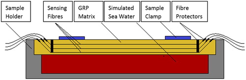
To simulate conditions experienced by a pipeline, samples containing multiple embedded glass fibre sensors were submitted to degradation tests in pressurised steel vessels that exposed a single face to simulated sea waterCitation26 at 120°C, and a vapour pressure of ∼2 bar. Exposure times up to 96 h were used for configuration A and up to 9 h for configuration B. shows the configuration of one stack of embedded fibres and the Al alloy sample holder for the exposure testing. The samples containing embedded glass fibre sensors were constrained within the sample holder using aluminium fixtures on the top and sealed with silicone to avoid water egress. This test configuration does not allow in situ real time monitoring: the samples were cooled to room temperature and removed from the steel vessel before optical measurements could be performed.
1 Schematic of vinyl ester/GRP sample containing embedded optical sensors, in sample holder for exposure testing (single side exposure configuration)
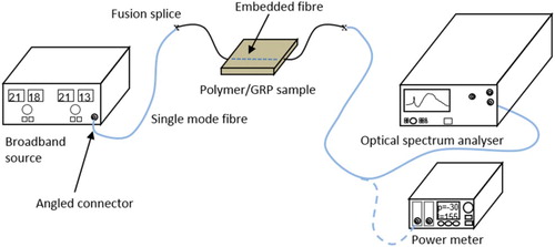
The optical characterisation was performed by coupling a broadband signal into the fibre and measuring the spectrum at its output (). The amplified spontaneous emission from an erbium doped amplifier (Photonetics 3626) emitting ∼5 mW in the range 1500–1600 nm was used as the source. The spectra of all fibres were measured with an optical spectrum analyser (OSA; Hewlett-Packard 70951). Alternatively, the fibre sensor output could be connected to an optical power meter (Agilent 81533B) to check the loss over the entire spectrum. The fibres were connected to both the OSA/power meter and the light source using pigtails with preassembled angled connectors in order to minimise back reflections and spurious cavities that could produce a distortion in the spectra. Pigtails and sensor fibres were cleaved (Fujikura CT07 high precision cleaver) and spliced using a fusion splicer (Fujikura FSM-40S). All the measurements were carried out at room temperature.
2 Schematic of optical fibre monitoring set-up
The diffusion coefficient of the neat epoxy vinyl ester resin was measured by exposing three specimens (110 mm × 90 mm × 6 mm) in sea water at 120°C at vapour pressure of ∼2 bar (full immersion) and performing gravimetric measurements until saturation. Moreover, the glass transition temperature of the cured resin was measured before and after sea water saturation with dynamic mechanical analysis (Perkin Elmer DMA 8000). Specimens (10 mm × 5 mm × 3 mm) were tested in a single cantilever configuration with an applied frequency of 1 Hz and temperature ramp rate of 2°C min− 1. To understand the effect of the exposing temperature to the material, glass transition temperature was also measured on specimens aged in a dry environment at 120°C for the same period of time as those soaked in sea water.
Polished cross-sections of the GRP sample containing multiple embedded glass fibre sensors were characterised by scanning electron microscopy (Philips 525 M) equipped with energy dispersive spectroscopy analyser (Philips SW9100 EDAX).
Results and discussion
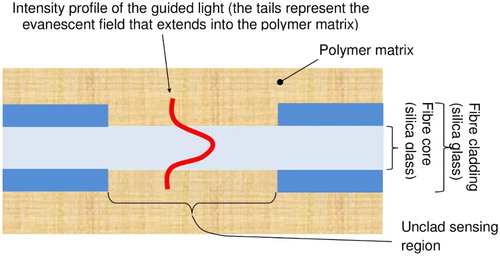
A diagram of the fibre configuration used for the evanescent wave sensors is shown in . The cladding of the glass optical fibre is removed, and the evanescent field interacts with the environment surrounding the fibre. The penetration depth of field is typically 1–3 μm. The stability of these evanescent sensors and their capability to interact with the surrounding media has been demonstrated and reported elsewhere.Citation27 When the sensor is embedded in the composite, the polymer matrix replaces the passive cladding and acts as a sensing material. Any change to the optical or structural characteristics of the polymer in this area provokes a change in the effective index of the optical fibre, thus changing its transmission properties.
3 Principle of operation of evanescent wave optical fibre sensor embedded in structure to be monitored
Sea water absorption of the neat vinyl ester resin specimens soaked at 120°C was very rapid, and saturation was achieved within 72 h for fully immersed specimens. The diffusion coefficient was measured equal to 6.36 × 10− 11 m2 s− 1. The glass transition temperature (Tg) of the dry specimens was 103°C and only reduced to 97°C following saturation. The small reduction of the Tg could be a result of the very high temperature used in the accelerated aging process, which, on one hand, enabled the fast sea water absorption and, on the other, could have mobilised some further cross-linking in the material. The Tg of dry aged specimens at 120°C for the same period of time as those soaked in sea water increased by 8–111°C, verifying that the final wet Tg is a balance between the sea water absorbed by the polymer and the aging at 120°C taking place at the same time.
The Fourier transform infrared spectroscopy analysis, performed on vinyl ester samples after the exposure to sea water at 120°C for up to 192 h (reported and discussed in previous workCitation27), confirmed that there is an increase in the intensity of the OH stretching peak related to the absorption water into the resin, while no significant changes in the spectra for the region associated with hydrocarbon bonding were observed. This means that any change in the optical signal received from the sensors is a result of the diffusion of water into the GRP and not the degradation of the vinyl ester itself.
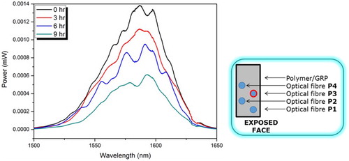
shows the optical spectra obtained for a series of evanescent field sensors embedded in vinyl ester resin (configuration A) with exposure times up to 96 h (single side exposure); there is a reduction in signal intensity with dwell time across the observed spectrum. The total transmitted power between 1500 and 1600 nm was calculated from and is plotted in against the dwell time in sea water. There is a rapid initial reduction in the signal intensity from 4.74 × 10− 2 to 1.35 × 10− 2 mW after 48 h of exposure, followed by a further reduction to 2.72 × 10− 4 × mW after 96 h as the water content increased.
4 Optical spectra (a) and transmitted power (b) from 1500–1600 nm obtained for evanescent field sensors embedded in vinyl ester resin (configuration A) with dwell time in sea water at 120°C of up to 96 h (single side exposure)
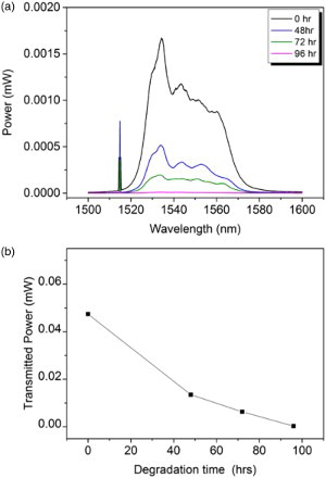
The evanescent field sensors were capable of measuring the diffusion of water into the resin, as shown in . The initial loss of signal in the first 48 h is due to rapid diffusion of water into the resin that causes changes in the optical characteristics of the polymer and, in turn, an increase in the propagation loss due to the interaction with the evanescent field tails. The rate of signal loss is reduced after the initial rapid diffusion and was expected to reach a plateau as the resin becomes saturated. The reason for the signal reduction due to moisture absorption is believed to be due to a change in the optical properties of the vinyl ester surrounding the evanescent sensor. As the water content of the resin increases, the evanescent field appears to interact more strongly with the resin and reduce the overall transmitted signal. The vinyl ester absorbs sea water; the refractive index of the resin is likely changed and allows more of the signal to be lost at the interface. These combined factors result in the large signal losses observed in this work.
The commercially available FBGs also detected the diffusion of water into the vinyl ester, although exploiting a different principle. The response of the FBGs after 48 h of degradation test showed a − 1.02 nm peak shift,Citation27 indicating a compressive force on the sensor that has changed the phase relation, which determines the Bragg wavelength. The corresponding axial strain on the FBG might be evaluated assuming a standard relationship Δλ/λ = 0.762ε(where λ is the wavelength and ε is the strainCitation12); this would correspond to ∼ − 850 με. When the sample absorbs sea water, the resin swells. For unconstrained samples, this would correspond to a strain increase and a positive wavelength shift.Citation20 In our test configuration, the samples are constrained within the stainless steel sample holders and the swelling of the resin leads to the formation of a compressive residual stress in the sample, as observed by the negative peak shifts measured by FBGs.
This preliminary result confirms the ability of both the EWOSs and the FBGs to detect the absorption of moisture in polymer materials by a reduction in the signal intensity and a wavelength shift respectively, after immersion in sea water at 120°C in a pressurised steel vessel. In order to simulate conditions experienced by a pipeline and detect water diffusion through the thickness of the GRP, single sided exposure tests were performed on composite samples with sensors embedded at different distance from the exposed face (referred to as configuration B in the experimental section).
The response of a sample constrained in the sample holder and underwent thermal cycling to 120°C in the absence of sea water was examined. This was to ensure that any change in optical response was caused by the exposure to sea water and not by distortions to the sample caused by thermal cycling while constrained in the X and Y directions. There was no significant change in the response of the control sample.
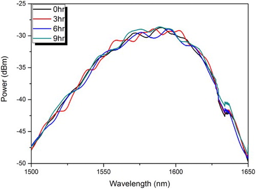
shows the response of a second control sample consisting of a series of copper coated evanescent sensors embedded in resin, constrained in the sample holder and exposed to thermal cycling at 120°C in the presence of sea water. In this figure, the data was plotted on logarithmic scales (decibel-milliwatts or dBm) to better highlight the differences of the spectra all over the range of interest (1500–1650 nm). The high degree of overlap of the curves highlights that that there was no change of the optical response, again showing that the fibres themselves were stable under the experimental conditions and any change in response of uncoated fibres could only be due to contact with water absorbed into the resin.
5 Transmitted signal of copper coated evanescent sensor embedded in vinyl ester resin exposed to high temperature (120°C) sea water in single sided sample holder for up to 9 h
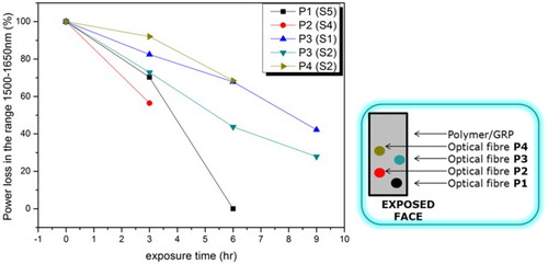
The evanescent wave sensors were capable of detecting the ingress of water from very early stages and exhibited a gradual reduction in transmitted signal intensity with time. This is shown clearly in where a fibre in position 3, the third sensor from the exposure face (inset in , sample configuration B), experiences a progressive transmitted signal intensity reduction, which reached 72% after 9 h. Given that the aim of this work was to monitor the diffusion of sea water through the thickness of the composite, the results in demonstrate that this can be achieved. A series of sensors embedded at different distances from the exposure face exhibited consistent behaviour of decreasing signal intensity with increasing water absorption. More importantly, the fibres that were closest to the exposed face (1 and 2, inset in ) experienced a faster and larger reduction in the transmitted signal intensity than the sensors embedded farther from the exposed surface (3 and 4). The fibre at position 2 experienced a higher loss than at position 1, as the data was acquired from two different samples (because of fibre failure), thus inducing an extra uncertainty to the loss values. However, the repeated measurements confirmed a decreasing trend of the loss as the distance between sensor and exposed surface increased. Unfortunately, the high mechanical failure rate of the fibres meant that it was not possible to calibrate the reduction in signal intensity with the time of exposure and distance from exposure face.
6 Transmitted signal of evanescent sensor in embedded in epoxy vinyl ester based GRP in position 3 (configuration B), confined in single sided sample holder and exposed to high temperature (120°C) sea water
7 Transmitted power loss observed for series of evanescent sensor embedded in epoxy vinyl ester based GRP (configuration B), confined in single sided exposed to sea water at 120°C for up to 9 h
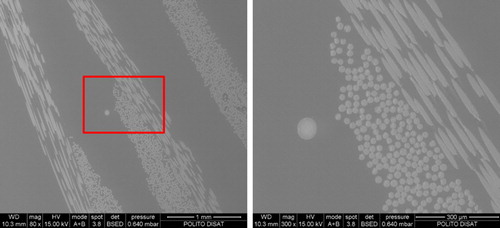
shows a cross-section of a composite with an embedded evanescent sensor after 9 h aging test. The interface between the polymer and the optical fibre is defect free, and no porosity or detachment could be detected. This measure was a confirmation that the loss could be attributed to a change of the guiding properties of the unclad fibres stemming from a change in the optical properties of the surrounding medium (which would not occur in the case of a corrupted fibre/GRP interface).
8 Cross-section of GRP sample with embedded optical fibre single sided exposed to sea water at 120°C for 9 h at a 80 × and b 300 × magnification
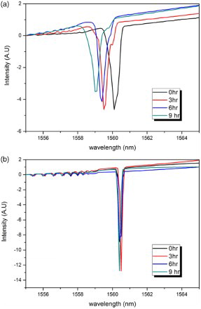
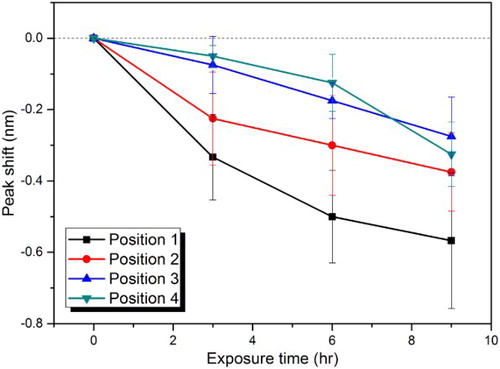
As well as the evanescent wave sensors, FBGs were also investigated. The responses of two typical FBGs are shown in . The fibre in position 1 (refer to inset in for fibre positions), shown in , exhibits a progressive negative peak shift with increasing dwell time. The fibre in position 4, shown in , however, shows no significant peak shift up to 9 h. This is shown more clearly in where the peak shift is plotted against time for a series of FBGs at different distances from the exposure face. There is a trend of increasing peak shift with dwell time for sensors embedded at all distances. As with the evanescent sensors, the fibres embedded in positions 1 and 2 (closest to the exposure face) showed a greater response than those in positions 3 and 4 (farthest from the exposure face). The large scatter in is believed to be due to variations in the embedding depth from one sample to the next. Small changes in the vertical positioning of the fibre have a large effect on the peak shift. This is a positive quality because it means that with a more accurate positioning procedure, the diffusion through the polymer could be very closely monitored.
9 FBG peak position observed after exposure to sea water at 120°C for up to 9 h of sensors embedded in epoxy vinyl ester based GRP in a position 1 and b position 4 (refer to inset in Fig. 7 for fibre positions, configuration B)
10 Average FBG peak shift observed for series of FBG embedded in epoxy vinyl ester based GRP after single exposure to sea water at 120°C for up to 9 h in positions 1–4 (refer to inset in Fig. 7 for fibre positions, configuration B)
There are advantages associated to both sensors for this field of applications. The FBGs are considerably more robust, making them easier to handle and embed. This is primarily due to the polymeric recoating across the sensing region. The evanescent wave sensors are over 10 times cheaper, which makes them more appealing on an industrial scale. Additionally, the evanescent wave sensors can be modified to be selective to certain chemicals or groups of chemicals though the use of sensitive coatings (e.g. fluorescent materials), whereas the FBG reacts solely to the mechanical force exerted on it. By carefully selecting coating materials for the evanescent wave sensor region, it may be possible to significantly increase the strength of the fibre, hence its survivability, making it less prone to failure due to handling.
An optimal solution could be to calibrate the peak shift observed for the FBG with the change in optical response of the evanescent sensor (coated or uncoated) and the moisture content of the polymer. Glass fibre sensors can be used for degradation detection since they are inert and can be easily embedded into the composites during manufacturing. With the correct combination of fibre sensors, it should be possible to detect both stresses and defects in the component, as well as any change in the chemical environment surrounding the sensor. The evanescent wave and FBG sensors would then complement each other and could provide additional information on the absorption rate of various chemicals in addition to the moisture absorption.
Conclusions
It was demonstrated that embedded glass fibre based evanescent wave sensors and FBG sensors were able to detect the early stage of sea water diffusion into a GRP polymer matrix after exposure to sea water at high temperature and pressure. The evanescent wave sensors showed a reduction in signal intensity with increasing exposure time attributed to a change in the optical properties of the resin surrounding the uncoated sensor. It was also possible to identify a trend of increasing signal loss for the same dwell time at a greater distance from the exposed face. The FBGs also responded to the absorption of sea water, exhibiting a negative Bragg peak shift due to the swelling of the resin constrained in stainless steel sample holders. As with the evanescent wave sensors, there was also a trend of increasing peak shift with increasing dwell times and proximity to the exposed face. The glass fibre based evanescent wave sensor is a very low cost device that has the possibility to be modified to increase selectivity to a wide range of chemicals. The incorporation of photonic sensors into GRPs for the hostile environments found in the oil and gas industry provides great development potential for this strategically important area, as well as other critical industries such as aerospace and renewable energy systems such as wind turbine blades. The extremely low cost associated with the production of the sensors in this work will allow them to be applied to the development of accelerated aging tests for the investigation and comparison of composite materials, an area that is being extensively investigated for the development of new GRPs. For some applications, users might consider failure of a pipe to have occurred once the liner has been compromised, i.e. the environment has diffused past the liner and into the structural part of the pipe. Further work is required to calibrate the embedded sensors for measuring the quantitative moisture content within composites.
Acknowledgements
The authors gratefully acknowledge Mr A. Toulitsis for assisting during the aging tests and Dr S. Perero for assisting with the coating deposition. The research leading to these results has received funding from the European Union's Seventh Framework Programme managed by REA-Research Executive Agency http://ec.europa.eu/research/rea and it participates in a Marie Curie Action (GlaCERCo GA 264526).
References
- RH Martin: ‘Degradation of polymer matrix composites’ Vol. 3, ‘Shreir's corrosion’ 2387–2406; 2010, Amsterdam, Elsevier.
- M. E. Hossain: ‘The current and future trends of composite materials: an experimental study’, J. Comp. Mater., 2011, 45, (20), 2133–2144.
- K. Nali: ‘Avoiding internal corrosion with glass reinforced plastic’, Pipeline Gas J., 2012, 239, (3), 1–3.
- A. M. Maffezzoli, L. Peterson, J. C. Seferis, J. Kenny and L. Nicolais: ‘Dielectric characterization of water sorption in epoxy resin matrices’, Polym. Eng. Sci., 1993, 33, (2), 75–82.
- M. Majumder, T. K. Gangopadhyay, A. K. Chakraborty, K. Dasgupta and D. K. Bhattacharya: ‘Fibre Bragg gratings in structural health monitoring—Present status and applications’, Sens. Actuators A Phys., 2008, 147, 150–164.
- H Tsuda and J-R Lee: ‘Strain and damage monitoring of CFRP in impact loading using a fiber Bragg grating sensor system’, Compos. Sci. Technol., 2007, 67, 1353–1361.
- Y. J. Yan and L. H. Yam: ‘Online detection of crack damage in composite plates using embedded piezoelectric actuators/sensors and wavelet analysis’, Compos. Struct., 2002, 58, 29–38.
- T Loutas and V Kostopoulos: ‘Health monitoring of carbon/carbon, woven reinforced composites. Damage assessment by using advanced signal processing techniques. Part I. Acoustic emission monitoring and damage mechanisms evolution’, Compos. Sci. Technol., 2009, 69, 265–272.
- T. J. Swait, A. Rauf, R. Grainger, P. B. S. Bailey, A. D. Lafferty, E. J. Fleet, R. J. Hand and S. A. Hayes: ‘Smart composite materials for self-sensing and self-healing’, Plast. Rubber Compos., 2012, 41, 215–224.
- K. S. C. Kuang, R. Kenny, M. P. Whelan, W. J. Cantwell and P. R. Chalker: ‘Embedded fibre Bragg grating sensors in advanced composite materials’, Compos. Sci. Technol., 2001, 61, 1379–1387.
- A. Papantoniou, G. Rigas and N. D. Alexopoulos: ‘Assessment of the strain monitoring reliability of fiber Bragg grating sensor (FBGs) in advanced composite structures’, Compos. Struct., 2011, 93, 2163–2172.
- DA Krohn: ‘Fiber optic sensors: fundamentals and applications’, 3rd edn, ‘ Research Triangle Park, NC, Instrumentation, Systems and Automation Society’., 109–154; 2000.
- Y-J. Rao: ‘Recent progress in fiber-optic extrinsic Fabry–Perot interferometric sensors’, Opt. Fiber Technol., 2006, 12, 227–237.
- O. S. Wolfbeis: ‘Fiber-optic chemical sensors and biosensors’, Anal. Chem., 2004, 76, 3269–3283.
- C. McDonagh, C. S. Burke and B. D. MacCraith: ‘Optical chemical sensors’, Chem. Rev., 2008, 108, 400–422.
- A Neri, M Parvis, G Perrone, S Grassini, E Angelini and D Mombello: ‘Low-cost fiber optic H2S gas sensor, 2008 IEEE Sensors’, IEEE, 2008, 313–316.
- U. Willer, D. Scheel, I. Kostjucenko, C. Bohling, W. Schade and E. Faber: ‘Fiber-optic evanescent-field laser sensor for in-situ gas diagnostics’, Spectrochim. Acta Mol. Biomol. Spectrosc., 2002, 58, 2427–2432.
- RS Mahendran, VR Machavaram, L Wang, JM Burns, D Harris, SN Kukureka and F Fernando: ‘Proc. SPIE 7293, Smart Sensor Phenomena, Technology, Networks, and Systems 2009’, 2009, 72930C–9.
- MJ Lodeiro, T Young and MRL Gower: ‘Feasibility of moisture and humidity determination using optical fibre sensing in polymer matrix composites’, ‘ NPL Report MN 11’; 2013.
- LP Canal, R Sarfaraz, G Violakis, V Michaud, J Botsis and HG Limberger: ‘Experimental and numerical study of the moisture diffusion in adhesive composite joints’, ‘ Proc. 16th Europena Conference on Composite Materials (ECCM-16), Seville, Spain, 22–26 June 2014, Paper 456’
- TJ Young, MJ Lodeiro, MRL Gower and MB Sassi: ‘Systematic approach for the calibration of humidity sensitive polyimide recoated fibre Bragg gratings for measuring humidity and temperature and their application for measuring moisture absorption in polymers’, Meas. Sci. Technol., 2013, 24, 085101.
- A. Armin, M. Soltanolkotabi and P. Feizollah: ‘On the pH and concentration response of an evanescent field absorption sensor using a coiled-shape plastic optical fiber’, Sens. Actuators A Phys., 2011, 165, 181–184.
- S. K. Khijwania and B. D. Gupta: ‘Fiber optic evanescent field absorption sensor: effect of fiber parameters and geometry of the probe’, Opt. Quantum Electron., 1999, 31, 625–636.
- C. L. Linslal, P. M. Syam Mohan, A. Halder and T. K. Gangopadhyay: ‘Analysis and modeling of an optical fiber loop resonator and an evanescent field absorption sensor for the application for chemical detection’, Sens. Actuators A Phys., 2013, 194, 160–168.
- B. Lee: ‘Review of the present status of optical fiber sensors’, Opt. Fiber Technol., 2003, 9, 57–79.
- ASTM D1141 - 98(2013) Standard Practice for the Preparation of Substitute Ocean Water.
- B Milsom, M Olivero, D Milanese, M Roseman, S Giannis, R Martin, A Terenzi and M Ferraris: ‘Development and integration of innovative glass fibre sensors into advanced composites for applications in hostile environments’, Proc. 16th European Conference on Composite Materials (ECCM-16), Seville, Spain, 22–26 June 2014, Paper 611.