
Abstract
A degradable phosphate glass (ICEL) and a bioactive silicate glass (CEL2) were mixed in different ratios (wt-%: 100%ICEL, 70%ICEL–30%CEL2, 30%ICEL–70%CEL2, 100%CEL2; codes 100-0, 70-30, 30-70, 0-100) and then co-sintered to obtain three-dimensional porous scaffolds by gel casting foaming. Thermal analyses were carried out on the glass mixtures and were used as a starting point for the optimisation of the scaffold sintering treatment. The microcomputed tomography and field emission scanning electron microscope analyses allowed the selection of the optimal sintering temperature to obtain an adequate structure in terms of total and open porosity. The scaffolds showed an increasing solubility with increasing ICEL glass content, and for 30-70 and 0-100, the precipitation of hydroxyapatite in simulated body fluid was observed. In vitro tests indicated that all the scaffolds showed no cytotoxic effect. The co-sintering of silicate and phosphate glasses showed to be a promising strategy to tailor the scaffold osteoconductivity, degradation and bioactivity.
Introduction
Bone tissue engineering aims to use three-dimensional (3-D) porous materials (i.e. scaffolds) to support and stimulate the regeneration of injured bone as an alternative to the use of autograft (the current gold standard). Scaffolds have to meet specific requirements in terms of morphological features and mechanical properties. The scaffold should elicit an adequate biological response without any cytotoxic effect due to the material or its degradation products; for degradable materials, the degradation rate has to be carefully tailored in order to match that of the regenerating tissue.Citation1 The scaffold structure should have an interconnected porosity (40–70 vol.-%) for tissue ingrowth and vascularisation, minimum pore size of 100 μm for cell migration and >200–300 μm for the enhancement of direct bone formation and new vessel formation.Citation2 All this features have a great influence on the mechanical properties of the scaffold, which should provide adequate mechanical stability, especially in the first phase of the bone regeneration process.
Glasses have been widely studied for bone applications since Hench and co-workersCitation3 developed the first bioactive glass, called Bioglass®. Silica based bioactive glasses are able to firmly bond to both hard and soft tissue by the precipitation of hydroxycarbonate apatite (HCA) (i.e. the mineral phase of natural bone) on their surface when put in contact with physiological fluids; moreover, ion release from these glasses induces the up-regulations of genes in osteoprogenitor cells, enhancing bone regeneration.Citation4 Phosphate glasses have also been proposed for the fabrication of degradable bone scaffoldsCitation5–Citation7 due to their solubility in aqueous media, which is strongly influenced by the glass composition.
In this work, powders of a degradable phosphate glass (ICEL)Citation8,Citation9 and of a bioactive silicate glass (CEL2),Citation9,Citation10 both developed at Politecnico di Torino, were co-sintered to obtain 3-D porous scaffolds with tailored bioactivity and degradation. The co-sintering of glasses deriving from different forming oxides (i.e. SiO2 and P2O5) is expected to impart to the obtained material a combination of the properties of the two glasses, that is, the degradation of the phosphate based glass and of its derived crystalline phases and the bioactivity of the silica based glass. The ratio between the two glasses is also expected to influence the predominance of one property over the other, thus allowing to obtain scaffolds with very different properties while using the same starting materials.
Using glass powder as the starting material, glass–ceramics porous scaffolds can be produced with different techniques aiming to reach a high volume of open macroporosity. In this context, some techniques can be mentioned such as the burn-out of a porogen,Citation11 sponge replication,Citation10,Citation12 freeze casting,Citation13 H2O2 foamingCitation14 and gel cast foaming technique.Citation15,Citation16 In this work, the gel cast foaming technique was used in combination with freeze drying and the authors focused their work on the optimisation of the scaffold structure and on the characterisation of the optimised scaffolds. In particular, the analysis of the phase composition and preliminary tests on the scaffold bioactivity, dissolution and biocompatibility to investigate the influence of the different ICEL/CEL2 ratios on the final scaffold properties were carried out. After the optimisation of the scaffold structure and the maximisation of their porosity, the aim of future studies will be to assess that the mechanical properties of the scaffolds are suitable for bone applications.Citation17–19
Experimental
Glass powder mixtures
Preparation of glass powder mixtures
ICEL (molar composition 45% P2O5, 3% SiO2, 26% CaO, 7% MgO, 15% Na2O, 4% K2O) and CEL2 (molar composition 45% SiO2, 3% P2O5, 26% CaO, 7% MgO, 15% Na2O, 4% K2O) glasses were prepared by the melt quenching process. ICEL precursors [(NH4)2HPO4, SiO2, Ca3(PO4)2, Na3PO4.12H2O, Mg3(PO4)2.8H2O, K2HPO4] were placed into a Pt/Rh crucible for melting at 1200°C in air for 1 h (heating rate 10°C min− 1) and poured on a brass plate. The precursors of CEL2 [SiO2, Ca3(PO4)2, CaCO3, (MgCO3)4.Mg(OH)2.5H2O, Na2CO3, K2CO3] were placed into a Pt crucible for melting at 1500°C in air for 1 h (heating rate 10°C min− 1) and then quenched into cold water. The glasses were then ball milled and sieved ( < 32 μm).
ICEL and CEL2 powders were mixed in different ratios (wt-%: 100%ICEL, 70%ICEL–30%CEL2, 30%ICEL–70%CEL2, 100%CEL2; codes 100-0, 70-30, 30-70, 0-100 respectively) as reported in . It was not possible to obtain a good sintering of a mixture of 50%ICEL–50%CEL2 (wt-%), and for this reason, this glass ratio has not been further investigated.
Table 1 Amount of ICEL and CEL2 glasses in different glass powder mixtures
Differential thermal analysis and hot stage microscopy
Differential thermal analysis (DTA; Netzsch DTA 404 PC) was carried out on the different glass mixtures (heating rate 10°C min− 1), and the glass transition (Tg), the onset crystallisation (Tx) and the peak crystallisation (Tc) temperatures were determined. Hot stage microscopy (HSM; Misura, Expert System Solutions, Modena, Italy) was carried out (air atmosphere, heating rate 10°C min− 1) in order to study the sintering process of the different glass powder mixtures (cylinder of pressed glass powder, diameter 1 mm, height 3 mm). HSM software automatically reports the height % (i.e. percentage of the sample height referred to the initial sample height) at the investigated temperatures and the melting point (i.e. temperature at which the height of the samples shrinks to under a third of the base). The melting temperature (Tm) was determined by the information obtained by both HSM and DTA results.
Scaffold preparation
Gel cast foaming
The scaffolds were prepared using the gel cast foaming methodCitation15,Citation16 combined with freeze drying (). Gelatin from porcine skin (Sigma-Aldrich) was dissolved in bidistilled water at 40°C under magnetic stirring to obtain a 50 mg ml− 1 gelatin/water solution. The glass powder (1.25 g ml− 1) and the surfactant (2%, v/v, Triton X-100, Sigma-Aldrich) were then added into the solution. A vigorous agitation was carried out in order to induce the foaming of the suspension. The obtained porous structure was then stabilised through the gelatin gelation in an ice bath, before the freeze drying process. A thermal treatment was then carried out in order to remove the gelatin and to sinter the glass powder mixture.
1 Scheme of scaffold preparation
Sintering and porosity optimisation
On the basis of the results of DTA and HSM results, sintering treatments at different temperatures were carried out on samples of the lyophilised glass/gelatin porous materials (10 × 5 × 5 mm) placed on a Pt lid (1 h, heating rate 10°C min− 1) to thermally remove the gelatin and to sinter the glass powder. The sintering treatment was optimised in order to obtain both a satisfactory densification and a high scaffold porosity.
Scaffold characterisation
Microcomputed tomography and field emission scanning electron microscopy
The samples were analysed with microcomputed tomography (micro-CT, Skyscan 1174, Bruker) after the thermal treatment. Using the CTAn software, after the segmentation of the images, a 3-D morphometric analysis was carried out to evaluate the scaffold total and open porosity percentage. The more promising scaffolds in term of morphological features were then analysed with field emission scanning electron microscopy (FESEM; SUPRATM 40, Zeiss) to assess the quality of the sintering. Combining the results of micro-CT and FESEM analysis, the appropriate sintering temperatures for the different glass powder mixtures were selected.
X-ray diffraction analysis
Scaffolds obtained using the optimised sintering conditions were ground and then crushed powders were studied by X-ray diffraction (XRD) analysis (X'Pert diffractometer, Bragg–Brentano camera geometry with Cu Kα incident radiation) to assess the formation of crystalline phases upon the thermal treatment.
Bioactivity and dissolution test
Three samples of each scaffold type (5 × 5 × 5 mm3) obtained using the optimised sintering conditions were soaked in 20 ml of simulated body fluid (SBF) and stored in an incubator at 37°C (refresh of the SBF twice a week). After 4 weeks of soaking, the scaffolds were washed with bidistilled water, dried at room temperature and weighted. The mass loss of the samples was calculated as follows:
(1) where m is the sample mass after 4 weeks of soaking in SBF and m0 is the sample initial mass.
FESEM analysis was carried out on the scaffolds after 4 weeks of soaking in SBF to assess the nucleation of HCA on the scaffolds.
In vitro test
In vitro cell culture tests with human osteosarcoma (HOS; CRL 1543) osteoblasts (5 × 10⁵ cells, 3 ml medium, refresh every 2 days) were performed on 5 × 5 × 2 mm3 scaffolds obtained using the optimised sintering conditions to investigate the in vitro biocompatibility. The cells were cultured in DMEM (1 g L− 1 glucose) with 10% fetal calf serum and 1% antibiotics in an incubator, at 37°C with 5% CO2. Cells (500 × 103) were seeded on the upper surface of each scaffold with 3 ml of medium. The medium was refreshed every 48 h. At different incubation time points (2, 5, 7, 14 and 21 days), the scaffolds were removed from the medium and washed in phosphate buffered saline (PBS) solution; then, they underwent eosin or fluorescence (DAPI/Vybrant) staining for cell observation using a light and fluorescence microscope.Citation20
Results and discussion
DTA and HSM
The graphs related to DTA and HSM analysis for the different glass powder mixtures are reported in , while the obtained characteristic temperatures are summarised in .
2 Graphs of thermal analysis on ICEL glass (a1, DTA; a2, HSM), on 30-70 glass mixture (b1, DTA; b2, HSM), on 70-30 glass mixture (c1, DTA; c2, HSM) and on CEL2 glass (d1, DTA; d2, HSM); HSM results show both height % curve and sample picture at melting temperature individuated by HSM software (i.e. temperature at which height of samples shrinks to under third of the base)
Table 2 Characteristic temperatures of glass powder mixtures
For what concern the DTA results, as expected, the characteristic temperatures found for 100-0 (ICEL phosphate glass) () were lower than those of 0-100 (CEL2 silicate glass) (). Both glass mixtures 70-30 and 30-70 showed Tg (418 and 421°C respectively) close to that of ICEL (Tg 410°C). These low Tg can be explained considering that, during the heating of the glass mixtures, ICEL glass is the first one that undergoes the glass transition process, while CEL2 has not reached it yet. The Tx for 70-30 and 30-70 (∼535°C) were lower than those of ICEL glass (568°C) and were close to the Tg of CEL2 glass (529°C). It can be supposed that when CEL2 reaches its Tg, ion diffusion between the CEL2 and ICEL powders occurs, leading to a change in the composition of the glasses. In fact, co-sintering of glasses with different compositions usually represents a system showing unlimited mutual solubility, which contains, at intermediate stages, the initial glasses and a solid solution of variable concentration.Citation21 This can lead to a change of the nucleation temperatures of the crystalline phases or even the nucleation of crystalline phases different from those that would nucleate in the two glasses alone (see the ‘XRD analysis’ section).
When considering the 100-0 sample (ICEL glass) HSM curve (), the shrinkage of the sample started at 420°C, just above Tg (406°C), due to viscous flow, stopping at ∼560°C. In fact, a remarkable increase of the viscosity occurred during crystallisation (Tx 568°C) and this is likely to inhibit viscous flow sintering.Citation22 For 100-0, the final shrinkage at the end of to the densification process was ∼45% and Tm was 660°C, according to the melting point found by HSM (see HSM picture in ) and DTA analysis.
For 70-30, HSM results () show that the shrinkage of the samples took place from 460°C, ∼40°C above the Tg (418°C); thus, the presence of CEL2 caused a delay in the sample shrinkage if compared to ICEL. Moreover, the sample showed a significantly lower shrinkage ( ≈ 6%) at the end of the first densification step if compared to ICEL at the same temperature ( ≈ 35%); this is realistic since this densification step can be ascribed mainly to the viscous flow of the 70% of ICEL in 70-30, as CEL2 is still below its Tg. The densification stopped at ∼530°C, when the crystallisation process occurs (Tx 537°C). A further increase in the temperature led to a decrease in the viscosity, leading to a second densification step at ∼800°C ( ≈ 32% of shrinkage), and a melting point at 1000°C was found. After melting, 70-30 showed a slightly irregular shape (see HSM picture in ) if compared to the typical rounded shape found for the other samples. This aspect could be due to a second crystallisation of 70-30 at ∼820°C.
A different behaviour was found for 30-70 analysed by HSM () as the sample shrinkage began at ∼1050°C, a significantly higher temperature compared to the Tg (421°C). In fact, the Tg in the 30-70 mixture (30 wt-% ICEL–70 wt-% CEL2) is due to the presence of ICEL glass, which, however, is not the main component of the mixture. Densification did not occur even above 530°C, which is the Tg of CEL2, the main component of the mixture (see ). Since crystallisation began above this temperature (Tx 532°C and 762°C), it can be supposed that the densification and viscous flow of the glass powder is hindered by the viscosity increase associated to crystallisation. Finally, the increase of the temperature led to a decrease of the viscosity and a densification of the samples occurred above 1050°C ( ≈ 18 shrinkage %). HSM analysis indicated the melting point of the sample at 1110°C.
As regard HSM result for 0-100 (CEL2 glass) (), a shrinkage of the sample occurred just after Tg (529°C) and continued until the crystallisation took place (662°C), reaching a final shrinkage of 34% at the end of the densification process. The sample showed a final expansion step (>960°C), probably related to a second crystallisation process in which the increase in volume was not balanced by shrinkage since full densification was already complete; this behaviour is in accordance to a previous study.Citation22 Melting temperature of this sample was ∼1100°C, according to both HSM results (melting point at 1085°C, see HSM picture in ) and DTA melting peak at 1100°C.
Sintering and porosity optimisation
Different thermal treatments were performed in order to optimise the temperature and times that would allow a proper balance between a satisfactory densification and high scaffold porosity. The total and open porosity percentages of the scaffolds were measured using 3-D morphometric analyses carried out after segmentation of the micro-CT images, while the scaffold sintering quality was investigated using FESEM.
summarises the sintering treatments that were carried out and reports an example of a 3-D model of the scaffold obtained from micro-CT analysis using CTvox software.
3 Summary of the results of sintering trials for different glass powder mixtures: a all sintering trials reported on HSM curves and example of 3-D model of scaffold obtained from micro-CT results using CTvox software (white lines in three directions correspond to 1 mm); examples of sections of scaffolds derived by micro-CT analysis and FESEM images: 100-0 (ICEL) scaffold sintered at 610°C: section of scaffold derived by b micro-CT analysis (porosity 62 vol.-%) and c FESEM micrograph; 70-30 scaffold sintered at 700°C: section of scaffold derived by d micro-CT analysis (porosity 75 vol.-%) and e FESEM micrograph; section derived by micro-CT analysis of 70-30 scaffolds sintered at f 750°C and g 1100°C, both showing collapse of scaffold structure and very low porosity ( < 25 vol.-%); 30-70 scaffold sintered at 1000°C: section of scaffold derived by h micro-CT analysis (porosity 69 vol.-%) and i FESEM micrograph, showing poor sintering quality; 30-70 scaffold sintered at 1100°C: section of scaffold derived by l micro-CT analysis (porosity 55 vol.-%) and m FESEM micrograph; n section derived by micro-CT analysis of 30-70 scaffolds sintered at 1250°C, which shows collapse of scaffold structure and very low porosity (14 vol.-%); 0-100 (CEL2) scaffold sintered at 610°C: section of scaffold derived by o micro-CT analysis (porosity 56 vol.-%) and p FESEM micrograph, showing poor sintering quality; 0-100 (CEL2) scaffold sintered at 640°C: section of scaffold derived by q micro-CT analysis (porosity 47 vol.-%) and r FESEM micrograph; s section derived by micro-CT analysis of 0-100 (CEL2) scaffolds sintered at 950°C (porosity 40 vol.-%)
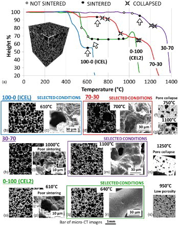
As regard pure ICEL and CEL2 compositions, the first sintering treatment was carried out with the conditions previously optimised for the preparation of glass ceramic scaffolds by the sponge replication method, which are 610°CCitation6,Citation9 and 950°CCitation10 respectively.
As regard 100-0 (ICEL) scaffold, it was possible to obtain high porosity (62 vol.-%, completely interconnected) with a thermal treatment at 610°C (), and thus, no further thermal treatments were carried out.
For 70-30, thermal treatments at 1100°C (), 1080°C, 920°C, 800°C and 750°C () were tested, but they all produced a collapse of the scaffold structure (porosity < 25 vol.-%). Finally, at 700°C, a porosity of 75 vol.-%, completely interconnected and a good strut densification were obtained ().
For 30-70, a thermal treatment at 1250°C () resulted in a collapse of the scaffold (porosity 14 vol.-%), while a treatment at 1220°C produced a well sintered structure with a porosity of 45 vol.-%. To further increase the porosity of the scaffold, lower temperatures were also tested. No sintering was achieved at 950°C, while a treatment at 1000°C resulted in scaffolds with an interconnected porosity of 69 vol.-%, but the degree of sintering was not optimal, as assessed with FESEM analysis (). Finally, thermal treatment at 1100°C resulted in a well sintered scaffold with a porosity of 55 vol.-%, completely interconnected ().
With regard to 0-100 (CEL2), sintering of the scaffold was obtained at 950°C with an interconnected porosity of 40 vol.-% (); to increase the porosity, treatments at lower temperatures (900, 800 and 700°C) were performed, obtaining similar results. By further decreasing the temperature to 550°C, no sintering was achieved. A treatment at 610°C resulted in a porosity of 56 vol.-%; however, FESEM analysis showed that the sintering quality was not satisfactory (). A further trial at 640°C resulted in a well sintered scaffold with a porosity of 47 vol.-% (), and thus, this temperature was chosen as the optimal one.
At the end of this optimisation phase, the selected sintering temperatures were 610°C for 100-0 (ICEL), 700°C for 70-30, 1100°C for 30-70 and 640°C for 0-100 (CEL2). Scaffold total porosity was 62, 75, 51 and 47 vol.-%, completely interconnected, and the mean pore size was 170, 216, 118 and 185 μm respectively for 100-0 (ICEL), 70-30, 30-70 and 0-100 (CEL2) scaffold. All the scaffolds showed pore sizes ranging from 10 to 400–500 μm. In view of in vivo application, the obtained scaffold structure meets the requirements needed for both cell migration and new vessel formation.
XRD analysis
XRD spectra of the different scaffolds obtained using the optimised sintering conditions [i.e. 610°C for 100-0 (ICEL), 700°C for 70-30, 1100°C for 30-70 and 640°C for 0-100 (CEL2); 1 h at 10°C min− 1] are reported in . The co-sintering of different glasses (70-30 and 30-70 samples) resulted in the formation of crystalline phases (Ca2P2O7 for 70-30 and NaCaPO4 for 30-70) different from that found for the as such glasses ICEL [Ca2P2O7 and Na4Ca(PO3)6] and CEL2 [Na4Ca4(Si6O18)]. The nucleation of these new phases was attributed to diffusion phenomena between the two glasses, leading to compositional changes in the materials and influencing the nucleation and growth of the crystalline phases. As expected, the presence of the ICEL phosphate glass in the initial glass powder mixture had favoured the nucleation of phosphate crystalline phases over silicate phases during the sintering process, the latter being present only for the scaffold obtained from pure CEL2 powder.
4 XRD patterns of powders from ground scaffolds: a 100-0 (ICEL) scaffold sintered at 610°C (1 h); b 70-30 scaffold sintered at 700°C (1 h); c 30-70 scaffold sintered at 1100°C (1 h); d 0-100 (CEL2) scaffold sintered at 640°C (1 h)
In a previous work, CEL2 scaffolds obtained by the foam replication technique were sintered at 950°C and showed the nucleation of two crystalline phases [i.e. Na4Ca4(Si6O18) and Ca2Mg(Si2O7)].Citation23 With the gel cast foaming method used here, it was possible to attain CEL2 scaffold sintering at much lower temperature (640°C), which resulted in the formation of the sole Na4Ca4(Si6O18).
Bioactivity and dissolution test
The mass loss of the scaffolds obtained with the optimised sintering conditions after 4 weeks of soaking in SBF is reported in . As expected, increasing content of ICEL phosphate glass resulted in a rise of the mass loss of the scaffolds.
Table 3 Mass loss of different scaffolds after 4 weeks of soaking in SBF
The pH of the solution did not show significant changes during scaffold soaking, remaining in the physiological range (data not shown).
FESEM images on the scaffold surface and energy dispersive spectroscopy analysis (Ca/P ≈ 1,67) confirmed the presence of HCA on 30-70 () and 0-100 (CEL2) scaffolds (). The bioactivity of CEL2 glass–ceramic scaffold was already assessed in previous studies.Citation9,Citation10 As regard 30-70, the high bioactivity can be due to the presence of β-NaCaPO4 (β-rhenanite), which is known to react with water to transform into HCA, thus being a nucleation precursor for HCA formation.Citation24,Citation25
5 FESEM images showing hydroxyapatite (HA) on trabeculae surface of a, b 30-70 and c, d CEL2 scaffolds after 4 weeks in SBF
In vitro test
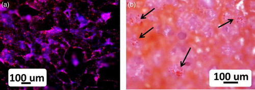
The evaluation of the cell morphology on all the scaffolds obtained with the optimised sintering conditions after 2 days of incubation with HOS osteoblasts cells showed the presence of the cells not only on the surface but also inside the pores of the different scaffolds. The fluorescence as well as the eosin staining revealed good cell attachment and development. In , representative examples of the results for CEL2 scaffold are reported. The same results were found at the different time points. This preliminary in vitro test indicated that all the scaffolds showed no toxic effect on cells.
6 HOS osteoblast cells on CEL2 scaffold after 2 days of incubation: images of a fluorescence microscope (DAPI/Vybrant fluorescent dyes) and b light microscope (eosin staining), showing cells both on surface and inside scaffold pores (arrows); both stainings, fluorescence and eosin staining, revealed good osteoblastic cell attachment and development
Conclusions
Porous 3-D glass–ceramic scaffolds were successfully obtained using the gel cast foaming methods by co-sintering a mixture of ICEL (phosphate glass) and CEL2 (silicate glass) in different ratios. The optimisation of the sintering conditions allowed the obtainment of scaffolds that fulfill the needed requirements in term of interconnected porosity, ranging between 47 and 75 vol.-% and pore size up to ∼500 μm. Moreover, the co-sintering of ICEL and CEL2 glasses in different ratios was effective for tailoring the dissolution rate of the scaffolds, which increased with ICEL glass content. Scaffolds containing higher CEL2 amount showed to be bioactive, inducing the nucleation of HCA on their surface in SBF. The scaffolds did not induce any toxic effect on cells. A mechanical characterisation and prolonged and more detailed study on the scaffold bioactivity and dissolution need to be carried out in order to better investigate the potential of these novel scaffolds for bone applications. From the results of the present study, it is possible to conclude that the combination of a phosphate and silicate glass proved to be an effective strategy to tailor the dissolution kinetics and bioactivity of the scaffold with the aim of matching the desired properties required for the specific clinical application.
Acknowledgements
The research leading to these results has received funding from the European Union's Seventh Framework Programme managed by REA-Research Executive Agency http://ec.europa.eu/research/rea and it participates in a Marie Curie Action (GlaCERCo GA 264526).
References
- L. C. Gerhardt and A. R. Boccaccini: ‘Bioactive glass and glass-ceramic scaffolds for bone tissue engineering’, Materials, 2010, 3, (7), 3867–3910.
- V. Karageorgiou and D. Kaplan: ‘Porosity of 3D biomaterial scaffolds and osteogenesis’, Biomaterials, 2005, 26, (27), 5474–5491.
- L. L. Hench, R. J. Splinter, W. C. Allen and T. K. Greenlee: ‘Bonding mechanisms at the interface of ceramic prosthetic materials’, J. Biomed. Mater. Res., 1971, 5, (6), 117–141.
- L. L. Hench: ‘Genetic design of bioactive glass’, J. Eur. Ceram. Soc., 2009, 29, (7), 1257–1265.
- E. Leonardi, G. Ciapetti, N. Baldini, G. Novajra, E. Verne', F. Baino and C. Vitale-Brovarone: ‘Response of human bone marrow stromal cells to a resorbable P2O5–SiO2–CaO–MgO–Na2O–K2O phosphate glass ceramic for tissue engineering applications’, Acta Biomater., 2010, 6, 598–606.
- C. Vitale-Brovarone, G. Ciapetti, E. Leonardi, N. Baldini, O. Bretcanu, E. Verné and F. Baino: ‘Resorbable glass-ceramic phosphate-based scaffolds for bone tissue engineering: synthesis, properties and in vitro effects on human marrow stromal cells’, J. Biomater. Appl., 2011, 26, (4), 465–489.
- E. A. Abou Neel, V. Salih and J. C. Knowles: ‘‘Phosphate-based glasses’: Compr’, Biomater, 2011, 1, 285–297.
- O. Bretcanu, F. Baino, E. Verné and C. Vitale-Brovarone: ‘Novel resorbable glass-ceramic scaffolds for hard tissue engineering: from the parent phosphate glass to its bone-like macroporous derivatives’, J. Biomater. Appl., 2014, 28, 1287–1303.
- C. Vitale-Brovarone, F. Baino, O. Bretcanu and E. Vernè: ‘Foam-like scaffolds for bone tissue engineering based on a novel couple of silicate-phosphate specular glasses: synthesis and properties’, J. Mater. Sci. Mater. Med., 2009, 20, (11), 2197–2205.
- C. Vitale-Brovarone, E. Vernè, L. Robiglio, P. Appendino, F. Bassi, G. Martinasso, G. Muzio and R. Canuto: ‘Development of glass-ceramic scaffolds for bone tissue engineering: characterisation, proliferation of human osteoblasts and nodule formation’, Acta Biomater., 2007, 3, 199–208.
- C. Vitale Brovarone, E. Vernè and P. Appendino: ‘Macroporous bioactive glass–ceramics scaffolds for tissue engineering’, J. Mater. Sci. Mater. Med., 2006, 17, 1069–1078.
- Q. Z. Chen, I. D. Thompson and A. R. Boccaccini: ‘45S5 Bioglass®-derived glass-ceramic scaffolds for bone tissue engineering’, Biomaterials, 2006, 27, 2414–2425.
- X. Liu, M. N. Rahaman and Q. A. Fu: ‘Oriented bioactive glass (13–93) scaffolds with controllable pore size by unidirectional freezing of camphene-based suspensions: microstructure and mechanical response’, Acta Biomater., 2011, 7, 406–416.
- H. Yuan, J. D. de Bruijn, X. Zhang, C. A. van Blitterswijk and K. de Groot: ‘Bone induction by porous glass ceramic made from Bioglass (45S5)’, J. Biomed. Mater. Res., 2001, 58, (3), 270–276.
- Z. Y. Wu, R. G. Hill, S. Yue, D. Nightingale, P. D. Lee and J. R. Jones: ‘Melt-derived bioactive glass scaffolds produced by a gel-cast foaming technique’, Acta Biomater., 2011, 7, 1807–1816.
- P. Sepulveda and J. G. P. Binner: ‘Evaluation of the in situ polymerization kinetics for the gelcasting of ceramic foams’, Chem. Mater., 2001, 13, (11), 3882–3887.
- B. Mondal, N. Mandal, S. Mondal, K. Mukherjee, S. Mukhopadhyay and A. Dey: ‘Optimisation of process parameters for fabrication of nanocrystalline TiO2-hydoxyapatite based scaffold using response surface methodology’, Adv. Appl. Ceram., 2014, 113, (3), 129–138.
- Z. C. Chen, X. L. Zhang, K. Zhou, H. Cai and C. Q. Liu: ‘Novel fabrication of hierarchically porous hydroxyapatite scaffolds with refined porosity and suitable strength’, Adv. Appl. Ceram., 2015, 114, (3), 183–187.
- J. Chen, G. Liu and T. W. Button: ‘Mechanical properties of porous TiO2 ceramics fabricated by freeze casting process’, Adv. Appl. Ceram., 2013, 112, (7), 436–441.
- R. Detsch, O. Guillon, L. Wondraczek and A. R. Boccaccini: ‘Initial attachment of rMSC and MG-63 cells on patterned Bioglass® substrates’, Adv. Eng. Mater., 2012, 14, (3), 38–44.
- A. E. Shilo, E. K. Bondarev and S. A. Kukharenko: ‘Sintering of low-melting glass powders and glass-abrasive composites’, Sci. Sinter., 2003, 35, 117–124.
- F. Baino, M. Ferraris, O. Bretcanu, E. Vernè and C. Vitale-Brovarone: ‘Optimization of composition, structure and mechanical strength of bioactive 3-D glass-ceramic scaffolds for bone substitution’, J. Biomater. Appl., 2011, 27, (7), 872–890.
- C. Vitale-Brovarone, F. Baino and E. Vernè: ‘High strength bioactive glass-ceramic scaffolds for bone regeneration’, J. Mater. Sci. Mater. Med., 2009, 20, 643–653.
- S. Jalota, S. B. Bhaduri and A. C. Tas: ‘A new rhenanite (β-NaCaPO4) and hydroxyapatite biphasic biomaterial for skeletal repair’, J. Biomed. Mater. Res. B Appl. Biomater., 2007, 80B, (2), 304–316.
- W. Gong, A. Abdelouas and W. Lutze: ‘Porous bioactive glass and glass-ceramics made by reaction sintering under pressure’, J. Biomed. Mater. Res., 2001, 54, (3), 320–327.