
Abstract
Blue Danube was the first British atom bomb deployed during the Cold War. The article focuses on practical issues of design, production, deployment, maintenance and testing of the weapon during the 1950s. Emphasis on scientific aspects of nuclear weapons means efforts to develop a workable technology have been overlooked.
Blue Danube did not follow the usual pattern of technical development: it was deployed first and tested later. The first weapons were hand-crafted prototypes delivered to the RAF for familiarization and active service, rather than a durable and reliable deterrent. As service life progressed, components were tested and the technology developed in terms of safety, fuzing and arming. Electronic circuits were modified to improve reliability within the same overall casing. So, Blue Danube is not one weapon — more a sequence of modifications in response to a succession of problems.
Development of the weapon required innovations in electronics, explosives and logistics. Conventional high explosive components were as much a constraint on deployment and serviceability as the novel radioactive parts. Learning how to manufacture, use, maintain and upgrade the weapon proved as important as building the device in the first place. The bomb was at the frontiers of practical application in electronic circuitry. Protecting electronic components by potting remained an uncertain art. Like many technologies, Blue Danube was a combination of the familiar and the advanced.
Understanding nuclear bomb theoretical modelling is an essential start but designing it takes a much greater effort; making it is the largest task of all.
Peter Jones, former Director, AWE (1999)Footnote1
Read at the Science Museum, London on 8 January 2014
Blue Danube was the first British atomic bomb deployed during the Cold War. There are accounts of the invention of the first atom bombs as part of the Manhattan Project and their subsequent re-invention in the Soviet Union and in Britain but these stories focus on the science and politics of early weapons development in an atmosphere of secrecy and espionage.Footnote2 History is largely silent on the physical technology and practical engineering of the first nuclear weapon in the UK.
The rapid technical development of Britain’s first atomic bomb is examined, focusing on practical issues of procurement, production, assembly, deployment, maintenance and testing. Neglect of the prosaic aspects of atomic weapons is understandable.Footnote3 Atomic bomb design is an unfashionable, even unwelcome, topic. The technology is complicated. It is shrouded in secrecy. Records are fragmented across Government Departments or incomplete. Some archive records have been withheld and some available records have been subsequently withdrawn.Footnote4
The neglect of technical development of the atom bomb in the UK distorts our view of how technology develops. Accounts of the bomb focus on a polite story of intellectual effort and formal science rather than engineering and practical technology. Interviews with those involved with Blue Danube design, production and deployment show an undocumented technological effort which encompassed a manufacturer of hot water bottles and a tank engine builder.Footnote5 Technicians struggled to perfect the production of items such as airbags, firing circuits and timing fuzes, often unaware of the full scope of the project they were working on.
This paper takes an evolutionary view and argues that Blue Danube was founded on local knowledge and pragmatic solutions which produced a deterrent that was modified as problems emerged.Footnote6 Development work was distributed widely. The weapon system was built on the back streets of northern towns such as Leeds, Barnsley and Mansfield and in southern suburbs such as Ilford, Weybridge and Shoreham as much as the more familiar sites of Woolwich, Aldermaston and Burghfield.Footnote7 Once the weapon came into service, feedback from RAF rehearsals, trial drops and volume manufacturing caused the bomb to be modified.
Those involved were often expert on one aspect of the bomb’s design, but kept in ignorance about other features of the weapon. Designs were given a ‘Top Secret Atomic’ classification. Information was provided on a ‘need to know basis’. As one respondent from Farnborough said, ‘other things were going on like Yellow Sun and Red Beard, but those were in the next office or the next office but one and I can’t tell you anything about them’.Footnote8 Or, as a former RAF officer said ‘You were encouraged not to be curious. You never talked about “top site” matters outside the wire. You never, ever talked about it in the Mess. It was just “verboten”’.Footnote9 Nevertheless, de facto cooperation emerged as key individuals shared knowledge up and down the supply chain, though not always fully aware of the precise significance of the information conveyed.
Development of Blue Danube
Blue Danube was conceived in secrecy and developed in haste. Work began before the go-ahead was given. Operational Requirement OR 1001 was issued in 1946.Footnote10 This initial specification for Blue Danube — the ‘special weapon’, or the ‘Bomb, Aircraft, HE, 10,000lb MC Bomb’ (initially, LC bomb), or ‘the store’, or ‘Small Boy’, or ‘Ten Thousand Pound Elsie’, as it was variously known — set the overall dimensions. The large size, weight and shape of the bomb were crucial as they determined the four designs for the new generation of jet-propelled V-bombers: Sperrin, Valiant, Victor and Vulcan. At the same time, the British Industrial Group of the Atomic Energy Organization began work in February 1946 to produce plutonium for use in bombs.
The formal decision to proceed with a UK atomic bomb was taken at a small cabinet committee GEN 163 on 8 January 1947.Footnote11 The first planning meeting to build the weapon took place in a curtained and stuffy Library at Woolwich Arsenal in June 1947.Footnote12 The first British-made nuclear explosion took place at the ‘Hurricane Trial’ on the Monte Bello islands, off Western Australia on 3 October 1952 — a decisive demonstration that the UK’s warhead concept worked. Delivery of the Blue Danube weapon commenced at the Bomber Command Armaments School at RAF Wittering on 7 November 1953.Footnote13 The first operational V-bomber, a Valiant, WP201, was delivered to the RAF on 15 June 1955. The first live drop from a Valiant at 30,000 feet took place at Maralinga on 11 October 1956, three years after the first bomb had been delivered to the RAF. The Air Ministry recognized ‘for political reasons, Blue Danube was introduced into the service at a fairly early development stage, which would normally be regarded as premature’.Footnote14
Pre-history of UK development
It is an irony of history that production of atomic bombs ceased briefly worldwide after their initial deployment at Hiroshima and Nagasaki and the post-war Bikini Atoll trials. When David Lilienthal became Chairman of the US Atomic Energy Commission in January 1947 he found just one deployable bomb in existence, few skilled personnel able to assemble other parts that were available and no capacity to manufacture more. The knowledge of how to build a bomb had been dispersed and the existing design had many shortcomings.Footnote15
Despite helping develop the first two atomic bomb designs as part of the Manhattan project and playing a part in the post-war tests at Bikini Atoll in July 1946, the British were cut off from any further American help by the terms of the USA’s McMahon Act which became law in August 1946. The UK Government decided they had to develop their own ‘special weapon’. The aim was to build a version of ‘Fat Man’ used at Nagasaki on the basis of partial knowledge acquired by British scientists working on the war time project.
An organization called Basic High Explosive Research was formed in June 1947 under the leadership of William Penney who had worked at Los Alamos from June 1944, witnessed the Nagasaki explosion and advised the Americans at the Crossroads’ trials at Bikini Atoll. William Penney had the official title Chief Superintendent, Armaments Research. Penney had both the formal knowledge and the tacit know-how to transfer the essentials of bomb production to his new team. Otherwise, members of the UK team involved in the Manhattan project had dispersed to other roles, although Klaus Fuchs, Egon Bretscher and the circuit designer Ernest Titterton worked at Harwell on atomic energy research.Footnote16
The project name was soon shortened to ‘High Explosives Research’ (HER) and the design team were given headquarters at Fort Halstead, Dunton Green, near Sevenoaks in Kent with production facilities at Woolwich and testing facilities initially at Foulness in Essex and later also at Orfordness in Suffolk.Footnote17 The RAF and the Royal Aircraft Establishment (RAE) were involved almost from the outset. In due course HER moved to a new site of its own at Aldermaston, a former airfield in Berkshire, which became part factory and part R&D laboratory.
As a result of incomplete knowledge, domestic production imperatives and the desire of technologist to modify, the UK bomb emerged as a local design. This fundamental redesign had major benefits:
Compared with the American weapons at the end of 1946 when all collaboration ended, the first British bomb had several advantages: about 20 per cent greater nuclear efficiency; easy change of explosive power; incomparably better ballistic and aiming qualities; rapid assembly; much safer loading; much improved firing circuits and detonators; sealed electronics, permitting release from a high altitude; and better storage characteristics.Footnote18
Design selection
Blue Danube worked by nuclear fission. In simple terms, a sub-critical mass of plutonium was slammed into another sub-critical mass of plutonium by implosion of a surrounding jacket of high explosive. Reducing the volume of two hemispheres of plutonium so rapidly means the nuclei find plenty of neutrons to fission, but little surface area to escape from. Fission releases huge quantities of energy and subsequent radioactive fall-out.
Two designs of atomic bomb were developed to fruition during the Manhattan Project of World War II. The first design triggered a chain reaction by firing a particle of uranium down a tube inside the bomb into a mass of uranium. This ‘Little Boy’ design was dropped over Hiroshima on 6 August 1945. While the design was straightforward, production of fissile material U235 proved a bottleneck. So much so, that the bomb exploded over Hiroshima had not been tested due to shortage of uranium.Footnote19
In the second design of atomic bomb, ‘Fat Man’, a chain reaction was triggered by reducing the volume of fissionable material — in this case plutonium — using high explosives to compress the material symmetrically and with great force. This was the design exploded during the Trinity Test north-west of Alamagordo, New Mexico on 16 July 1945 and above Nagasaki on 9 August 1945. Here the technical difficulty lay in the design of the complex implosion mechanism that triggered a critical mass. The US design was aerodynamically poor as its length was constrained by the short bomb bay of the B29 delivery aircraft.Footnote20
Supply of fissile material helped determine the choice of British design of atomic bomb. Plutonium was largely manufactured in what seems, in retrospect at least, a ‘cheap and cheerful’ way in an air-cooled graphite pile at Windscale in Cumberland.Footnote21 An adjacent chemical separation plant used solvent extraction to separate plutonium from uranium in the irradiated fuel rods. The uranium fuel rods for Windscale were made at Springfields, Salwick, west of Preston in Lancashire using chemical separation and vacuum casting. The hollow spherical tamper inside the high explosive shell of Blue Danube was natural uranium 238, also from Springfields. A tiny amount of polonium 210 known as an ‘urchin’ was needed as an initiator, providing an intense source of alpha particles at the moment of prompt criticality.Footnote22 This polonium was made from irradiated bismuth at Windscale, and later Risley. The scientific team may also have appreciated the ‘Fat Man’ design was less likely to go critical by accident than the ‘Little Boy’ alternative, while plutonium is fairly benign and easy to handle in small finished quantities compared to uranium 235.
Choice of the ‘Fat Man’ design for the UK atomic bomb had two consequences. Firstly, Blue Danube was large ( and ). Use of an implosion triggered by conventional high explosives resulted in a weapon weighing some 10,000 lb, just over 24 feet long and almost 62 inches in diameter.Footnote23 The overall bomb weighed 4½ tonnes, but perhaps 2½ tonnes of this were high explosive.Footnote24 Secondly, a key feature of the design was the double layer of explosive lenses that triggered the implosion. So, paradoxically, design and maintenance of high explosives and their accurate detonation were the key focus of an atomic bomb delivery system. Non-destructive testing of the explosive lenses using X-ray techniques became a key maintenance activity.Footnote25
FIGURE 1. Blue Danube, Britain’s first atomic bomb – shorter and fatter than a wartime Grand Slam.
© Crown copyright 2013, with permission
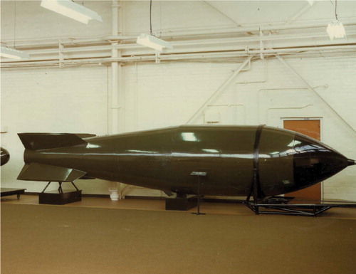
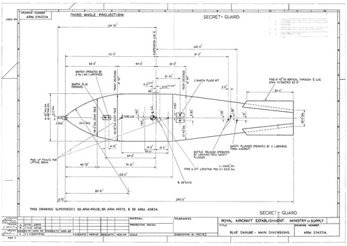
FIGURE 2. An early general arrangement drawing from ARL at Farnborough supplied to Vickers at Weybridge to help with design of the Valiant. The lifting lug and finger chopper plate for in-flight loading have been omitted for clarity.
RAF Museum Hendon
The Blue Danube design did not replicate the US ‘Fat Man’.Footnote26 The American case was heavily armoured. The British version was a light internally braced ballistic casing. The explosive sphere was redesigned from first principles using a combination of twelve pentagonal and twenty hexagonal shapes to form a sphere — not unlike the outer pattern of a modern soccer ball. The first version of the British bomb was primed in flight through In Flight Loading (IFL) of the core. The UK bomb was designed to work at higher altitudes and lower temperatures than its US equivalent.
Engineering design and the prototype
Penney’s approach to engineering design was the familiar method of breaking down the weapon into its key packages and entrusting design, development and testing of the sub-assemblies to small teams.Footnote27 HER at Fort Halstead set up four working parties to complement their in-house work on the core of the bomb ‘to ensure that all aspects of the project would receive adequate consideration’.Footnote28 These committees were named C, A, F and H which covered Ballistic Case and Supporting Structure (C); Aircraft Installations (A); Fuse (sic) (F) and Handling and Transportation (H). The overall weapon would then be assembled into a prototype from its components. In turn, each team was broken down into smaller groups and allotted specific tasks. This helped maintain secrecy. What appeared to be a highly centralized and directed project was, in truth, widely distributed in terms of delivery across both public bodies and private firms. The project involved a high degree of coordination behind a wall of secrecy.
While this process of deconstruction and reconstruction is a standard approach to engineering, it is not clear that many conventional engineers were involved in the lead team at HER at Fort Halstead.Footnote29 The initial team briefed by Penney — a mathematician — at Woolwich in 1948 was composed of a mix of scientists including chemists and fellow mathematicians.Footnote30 The conceptual and detailed design work for Blue Danube was undertaken within a narrow circle of government departments. This meant scientists were entrusted with production designs. As a result, ‘the design of the weapon is sound enough in principle, but unpolished in the engineering sense, leading inevitably to an expensive and long-drawn-out process of improving the design of many of the component parts’.Footnote31
The technologies of the Blue Danube bomb
The atom bomb was a set of technologies. It brought together pioneering electronics with novel nuclear materials and conventional, heavyweight explosives.Footnote32 The casing posed aerodynamic problems. Preparation of the fissile material required feats of chemical engineering.
The bomb was built up from six packages of components, each with its own set of development problems and manufacturing challenges. They were the outer ballistic casing; the suspension system for the central physics package (or warhead); the fuzes; the firing mechanism and detonators; the physics package combining a high explosive outer shell and the tamper, core and urchin; and, finally, a new set of organizational routines and facilities surrounding handling, storage and deployment. This omits associated developments which have commanded more public attention, such as a new generation of medium range jet bombers, the difficulties of making fissile material for the core, and the awkward nature of the nuclear testing process.
The ballistic casing and support structure — the role of RAE Farnborough
The outer ballistic casing and internal support structure illustrate the combination of public sector research and private sector manufacture required to build Blue Danube. What appears to be a simple, delegated task actually required considerable experiment, technical development, design work and engineering ingenuity.
The ballistic casing for an atom bomb has four functions. The outer shape of the case determines the bomb’s free-fall characteristics and accuracy. The strength of the case allows the bomb to be suspended in the bomb bay. The internal structure of the centre section holds the physics package in place and maintains gentle pressure on the outer explosive sphere. Finally, the casing encloses the arming mechanism, fuzes, firing mechanisms and batteries necessary to trigger the bomb. The front and rear casings also played a structural role as they were winched up against the fore and aft crutches in the bomb bay. At the front, a fibreglass radome allowed the primitive radar fuzes to operate.
The design, testing and supervision of the development of the overall bomb casing was delegated to the RAE whose central role in design work and managing contracts is underplayed in official accounts. The RAE was to become even more prominent in later weapon developments such as adaption of US hydrogen weapons, conceptual design of Blue Steel and design of WE177.Footnote33
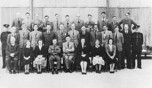
The RAE was involved in Blue Danube from 1948, not just on casing design and aerodynamics, but also the physical and electrical integration of the bomb into the aircraft. Farnborough had set up a division called ‘ARL’ — the ‘Airfield Radio Laboratory’. This innocuous name was retained as work began on Blue Danube under the leadership of Sid Hunwicks.Footnote34 Such misnomers were typical of the dissembling surrounding the weapon.Footnote35 RAE used a secure compound for atomic bomb development work located at the remote southern end of Farnborough airfield. This ARL compound had aircraft access and was occupied around 1950. It was in use by 1952 for bomb loading trials on the Valiant prototype flown in from Vickers at Weybridge (). Photographic evidence shows ARL had a staff of at least twenty-two engineers and ten support staff working on Blue Danube in 1953, protected by an armed special police unit ().
FIGURE 3. A prototype Vickers Valiant enters the ARL compound for bomb fitting.
Photo: RAE
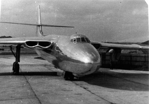
FIGURE 4. The Blue Danube development team at ARL Farnborough and ,‘Russian Spy’ around 1953. The interloper - Ivan - was smuggled in to the picture by Pete Barker. The picture shows the police and the RAF officers seconded to the development team as well as all the development personnel. The picture includes Sid Hunwicks, Reg Milne, John Allen. At the time of this photo by E. P. ‘Gred’ Greddington (top right) this was one of the most secret places in the world.
© RAE
The RAE was responsible for the design and ballistics of the complete casing and for elements of the implosion sphere such as the support structure and IFL. The casing had a flush riveted stressed skin over an inner airframe. The ballistic shape of the bomb was designed by Dr G. J. Richards. A programme of wind-tunnel testing, trials of rocket-propelled models and tests of 1/3.4 scale models, followed by full-scale trials at Orfordness were used to confirm the shape. Wind-tunnel testing at Farnborough revealed the singular predicament that the bomb was reluctant to leave the aircraft due to flow of air in the bomb bay with local lift at the nose and downward flow at the tail driving the weapon back up into the bomb bay. This would cause considerable embarrassment to the crew if the time-delay fuze kicked in.Footnote36
Two measures were taken to make sure the bomb did fall away from the aircraft. Blue Danube had four fixed fin stubs which were limited in span by the diagonal size of the bomb bay. Extendable ‘flip out’ fins were fitted to lengthen the span of these stubs or ‘fin gloves’. The flip-out fins were captured inside the fin stubs while it was stowed in the aircraft. The fins were deployed as soon as the bomb left the aircraft. This was achieved using compressed nitrogen to drive a single axial piston and four connecting rods, activated by a lanyard.Footnote37 The Valiants themselves were also fitted with six retractable dragon’s-teeth ‘fingers’ at the leading edge of the bomb bay to disturb the airflow to avoid the ‘nose-up’ effect which generated lift.Footnote38
The main casing of the bomb was fabricated by Hudswell Clarke at Leeds. The firm is best known for design and manufacture of industrial steam locomotives. They made the transition to aircraft, bomb and — later — rocket production through sub-contract work from November 1938, initially to Blackburn Aircraft’s Olympia Works on Roundhay Road, Leeds. The firm took over the works when Blackburn moved to Brough.Footnote39 They also made the centre section and nose of the various trial models, for which the tails were made by Follands.
The nature of the work at Hudswell Castle was apparent to the workforce:
Every man on the shop floor would know what they were working on, because inside the Blue Danube tail joint ring (and other similar items) was a small brass plate engraved with the customer’s name (Atomic Weapons Research Establishment) and a serial number. No one was so dumb as not to know who that was, even in 1956.Footnote40
Suspension system — Percival Aircraft
The suspension system for Blue Danube also shows how practical aspects of the technology were devolved to the RAE at Farnborough and onward to individual private contractors. A process of distributed problem solving which allowed HER at Aldermaston to get rid of their responsibilities for the delivery system. Again it involved the most unlikely participants.
The physics package had to be suspended inside the ballistic case and insulated from the severe vibration and buffeting the bomb would experience on a jet aircraft during take-off, climb and cruising in the cold upper atmosphere. Structural design of the centre section of the bomb was undertaken by Percival Aircraft of Luton.Footnote41 There were hefty aluminium front and back formers for the cylindrical centre section of the bomb casing. These were separated by a horizontal structure — a rigid but light ‘strong ring’ made of cast magnesium with a circular hole to provide multi-point support for the sphere
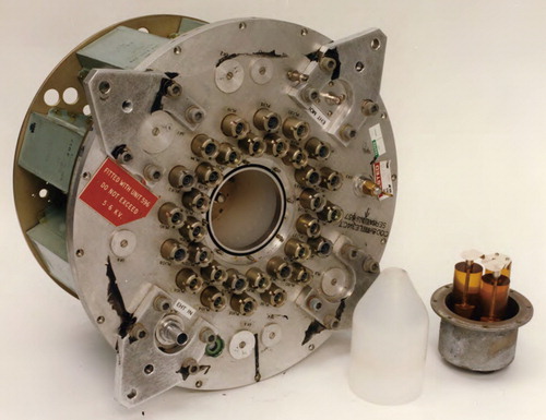
The outside of the explosive sphere was cushioned on thirty-two airbags matching each segment of explosive (). Each airbag had an opening to allow for insertion of the detonator. This patchwork of air bags was held in place by a hinged aluminium cover, again made up of the same combination of pentagonal and hexagonal plates. The plates were laced together with substantial piano hinges attached to each plate edge and threaded together by hinge pins of 20 gauge steel wire. This surface covering of tessellated plates spread the weight of the explosive package under gentle tension. The centre of each plate was also open to a detonator cap of about 6 inches diameter. Lugs were fixed on the cover plates all around the equator. The lugs were fixed to the strong ring by attachment bolts. In this fashion, the whole explosive sphere, weighing close on three tonnes, was gently and evenly suspended under slight pressure within a cosseting layer of air.
The butyl rubber airbags surrounding the explosive sphere were made by William Freeman& Company Limited in Barnsley, a well-known hot-water-bottle manufacturer (). Reg Milne recalls:
FIGURE 5. A mock-up of the physics package at ARL, Farnborough shows the plates covering the air bags surrounding the outer explosive shell, the detonators distributed evenly over the surface and a handling frame which supported the package. Reg Milne is the young man on the right.
© RAE
Dai Williams suggested air bags. I chose the rubber. I went to two firms, India Rubber, Gutta Percha and Telegraph Company where London City Airport is now and to a firm up in Barnsley. Now they made Suba-Seal hot water bottles amongst other things. They were a lot more accommodating and competent we thought. We settled on them.Footnote42
Reg Milne’s choices show the flexibility inherent in the devolved structure of decision-making. However, in contrast to the openness at Hudswell Clarke:
I am quite clear that Freeman and his salesman and staff had no idea of the purpose of the air bags — just that they were important and needed promptly. They were made in the same workshop with moulds made to fit in the presses that were being used for all the other products.
Fuzes
Technical development of the various fuzes used by Blue Danube was given over to Royal Ordnance at Woolwich, along with the related firing mechanism and detonators. The slow development of the whole firing circuit highlights the troubleshooting necessary to convert design ideas into workable technology. Their slow delivery became a bottleneck and prompted design reappraisals. The electronics of Blue Danube shows how design often evolves by solving a sequence of problems, only in this instance the technology was already in service.Footnote43
To ensure the bomb imploded, there were a variety of fuzes, all with duplicate circuits. The fail-safe approach made the circuitry complicated. Blue Danube was a free fall bomb built for an air burst in either a ‘high’ position at 2450 ft or ‘low’ position at 1082 ft. Detonation was triggered by a ground proximity fuze (or W/R fuze) — a simple form of radar located in the nose of the bomb ().Footnote44 Since each fuze was duplicated there were four proximity fuzes in the service weapon, arranged as a quadrant. To add to the difficulty, contracts for manufacturing these devices were divided for security reasons. Two outside suppliers — Plessey at Ilford and Peto-Scott at Weybridge — were responsible for supplying the proximity fuzes. In addition, Woolwich made the first fuzes used on the trial weapons. To add to the complexity, a clockwork time fuze was added, again duplicated ().Footnote45 If all else failed, either a graze fuze or a contact fuze detonated the weapon when it hit the ground.
FIGURE 6. The ground proximity fuze (W/R fuze) supplied by two different manufacturers to ensure secrecy. They were criticized for being unduly complex, but radar was an heroic technology after World War II.
Crown copyright 2013, with permission
FIGURE 7. The clockwork fuze. Delivery problems with the clockwork jeopardized Britain’s strategic deterrent. Shortcomings in the cocking mechanism that wound the fuze led to premature detonation, a problem resolved with extra washers to eliminate asymmetry in the winding plunger.
Crown copyright 2013, with permission
Supply was insufficient. So a ‘crash programme’ had to be set up in January 1955 to supply the ground proximity fuzes. This initiative seems to have been highly effective and the whole programme went up a gear during 1955 as the RAF Valiants were being commissioned. A design freeze was imposed. No more modifications were allowed. Production was switched to the Royal Ordnance Factory (ROF) at Burghfield. Key staff were loaned to suppliers. It was a classic instance of troubleshooting.Footnote46
Ironically, a shortage of clockwork delayed matters. A government evaluation of Blue Danube ruefully remarked: ‘instead of the supply of radio-active bomb components being the limiting factor, this doubtful distinction belongs to the Firing Installation and the Time Fuse’.Footnote47
Detonators and firing mechanism
Detonators were one area where US experience helped UK development. US technicians Luis Alvarez and Lawrence Johnston developed exploding wire detonators for ‘Fat Man’.Footnote48 These bridge wire detonators had the advantage they would vaporize simultaneously in microseconds in a predictable and precisely timed way thereby avoiding an asymmetric explosion where plutonium leaked out of one side of the sphere without forming a critical mass. These detonators were developed and tested at Fort Halstead but their manufacture was given to AWRE production unit located on Ha-Ha Road, Woolwich ().
FIGURE 8. Bridge wire detonators assembled by banks of women at Woolwich. They were ‘potted’ in a material akin to plaster of Paris.
Crown copyright 2013, with permission
Here rows of women worked with microscopes soldering together the electrodes and the platinum bridge wires — just two thousands of an inch in diameter and a tenth of an inch long — inserting them into plastic moulds and filling the moulds with PETN explosive to exactly the right density. […] The result at the end of the line was an object that came to be called an exploder, a little bigger than a tennis ball, rounded on one side to be set into the bomb with two large connectors sticking out on the other side to be joined to the cables.Footnote49
Development of the firing circuits, fuzes, secondary fail-safe fuzes and circuits was led at HER, Fort Halstead, by W. J. ‘John’ Challens, a former rocket scientist and future director of AWRE.Footnote50 This was frontier technology. Firing circuits provided a precisely timed high-voltage pulse to reach all thirty-two detonator sites at exactly the same moment. To this end, all of the firing cables were the same length. This meant detonators close to the firing unit had a length of excess cable coiled nearby. These firing circuits were to prove problematic, illustrating a familiar truth that it is often the subsidiary aspects of a technology that stand between success and failure, not the main technical principle itself.
Multipoint detonation of the thirty-two detonators was achieved with a high-voltage pulse. The firing mechanism had to discharge a precisely timed pulse to all of the detonators simultaneously (). This posed novel design problems.Footnote51 Details are partly classified, but it seems various designs were used. Early components shown to the author discharged a bank of eight condensers (now known as ‘capacitors’). These are devices which store an electric charge until required. They were prompted to discharge their pulse by a very large relay driven by the fuze current. Later photos show a pulse transformer which may be part of a more reliable design. (Pulse transformers are not dissimilar to the magneto once fitted to cars.) This too would need to be moderated by condensers to prevent arcing. But limited evidence and newly released documents suggest there were a variety of components used at various stages in the evolution of the weapon. In particular, there were problems with the unreliability of condensers.Footnote52
FIGURE 9. The final version of the firing unit with 32 sockets for each of the leads to the detonators spread round the outside of the physics package. This unit was duplicated giving a total of 64 leads to detonators.
Crown copyright 2013, with permission
The electrical pulse to the detonators needed to be discharged in less than a millisecond, requiring a very fast switching device. This was achieved using a trigatron, a glass valve filled with gas which ionizes instantly as a plasma, thereby allowing a current to pass through. It switches ionically, just like a flash of lightning. Trigatrons were widely used in radar as transmit/receive switches during the Second World War, but only had to perform at low altitudes, and even so were prone to explode. The design of trigatron for Blue Danube was altered at a crucial stage and maintenance records for RAF Barnham show they were temperamental in service use.Footnote53
A trigatron switch has another advantage. An electric pulse is usually a drawn-out distribution of current. (Consider the slow pace at which an old light bulb element illuminated when switched on.) A trigatron trims the slow build up and run down of current, giving a short, sharp burst instead. This current was then fed to the detonators.
These circuits were novel in the laboratory. The problem was to produce a reliable circuit which gave simultaneous switching regardless of temperature or air pressure, even after long periods of storage and despite vibration in flight. Just to make sure it worked, the firing mechanism was duplicated. As was remarked ‘By the very nature of the blast every effort had to be made to get 100% reliability’.Footnote54
Potting — a potted history of problems
High technology often stumbles on prosaic problems. Delivery of an atomic bomb posed new challenges for electronics. V-bombers were to fly at high altitudes and currents spark across gaps at the low air pressure existing at high altitudes. Flying high meant components cycled from warmth at ground level to extreme cold at high altitude — shrinking with drop in temperature. V-bombers were to be deployed in areas of high humidity, such as the tropics, bringing the problem of moisture ingress. Circuits would vibrate during take-off and flight creating mechanical stresses to break connections.
The solution to these problems was encapsulation of electronic components in resin through the arcane art of potting. This pioneering technology evolved in the late 1940s, but was not without shortcomings.Footnote55 It is difficult to get resin to bond to the components. Cracks and tracks might emerge as the resin shrinks giving alternative routes for stray currents. The durability of resins was not clear. The very process of encapsulation set up forces in components which could break soldered circuits. To add to the embarrassment, preparation of resin could be exothermic and resins would melt through plastic containers and heat up components. Many circuits which performed perfectly under test failed once they were encapsulated for use. For instance, a report on the proximity fuzes concluded: ‘cracking of a percentage of valves in Araldite blocks is envisaged’.Footnote56 The teething problems associated with potting are illustrated by attempts to manufacture the firing system.
Volume production of the firing mechanism was first entrusted to Whiteley Electrical Radio Company of Mansfield, Nottinghamshire. Whiteley was a private company founded in 1926 which specialized in loudspeakers for domestic radios and public address systems.Footnote57 Whiteley was an unlikely candidate for a crucial military electronics contract. However, the firm did have a vertically integrated production system, including electromagnets which were a key component of Blue Danube’s circuitry which amounted to a ‘mass of relays’.Footnote58 They would have set aside separate production facilities for the secret work.
Components of the firing unit included a power supply, a trigatron to switch the pulse, a pulse transformer, a trigger isolator and an arming unit. This was coupled with a trigger unit, a discriminator and a junction box. Everything was duplicated and all wired into a common frame behind the explosive sphere. Surviving units show components were built up on a frame and then substantially encased in transparent resin. Individual electronic components came from a range of UK manufacturers, including Norbury Watch Co. who made the trigatrons and BICC who supplied the eight specially designed EHT condensers for each unit.Footnote59
An initial order was issued to Whiteley in Mansfield for assembly of components in 1953 but there was insufficient detail for a complete contract; so the actual contract was not issued until 8 January 1954.Footnote60 Even then design details were not finalized. There were constant modifications up to the point where none of the twenty-five initial sets of firing units had been delivered by the end of 1954. By that time Blue Danube bombs had been delivered into RAF service. So the electronic component supply chain was a severe bottleneck. The contract with Whiteley began at an initial value of £255,000 but soon doubled as the modifications flowed in. Individual components proved unreliable and there were no agreed test procedures. In the meantime, firing units were being delivered by the research laboratory of ARE(C) at Woolwich Common as a stop-gap measure. Indeed, the first complete and fully tested production firing unit was not delivered from Mansfield until July 1955. All firing units had to be tested in Stratosphere Cabinets. Sub-units passed individual tests and were successfully built up into sub-assemblies only to fail on final assembly of the complete mechanism once ‘potted’ in Araldite. Arming Units, Trigatrons and EHT condensers were prone to failure at this stage.Footnote61
By the end of December 1955 Whiteley had still only delivered twenty-six firing installations out of the 120 planned. This was not helped by a change in Trigatron design in July 1955. The contract was finally rescinded in 1955 and ended in acrimony with the Ministry of Supply going to court to recover two stratosphere test cabinets loaned to Whiteley and not returned.Footnote62
The firing system contract was taken up by Dennis Ferranti Meters, at Bangor.Footnote63 The firing system for an atomic weapon presented an opportunity for new business to an aggressive newcomer. The firm specialized in precision assembly of meters. They had no experience of electronic components. Nevertheless, in 1955 a contract was issued for fifty-six firing units for £200,000 which proved successful. The components were assembled and tested amid great secrecy in a department with its own dedicated workforce, management and security ‘minder’.
Physics package
Conventional explosives were central to the workings of Blue Danube. A carefully structured globe of high explosives was needed to initiate the implosion. Casting of the segments of the fabricated high explosive ball was initially delegated to the Royal Arsenal, Woolwich and the resulting spheres were taken to Foulness in Essex for testing. But full-scale production moved to Royal Ordnance Factory (ROF) Chorley in June 1953. The ball was made up of pentagonal and hexagonal sections which tessellate together to form a sphere. The outer explosives were built up as ‘lenses’ so as to focus the blast on the centre of the sphere. During manufacture, the explosives were poured as liquids into moulds in two stages to form the lenses. When solidified, shaped lenses of RDX/TNT curved outside the inner cones of Baratol.
The plutonium core of Blue Danube remains secret, but it is clear the design evolved from that used by the original ‘Fat Man’ device. The warhead assembly was altered in service once practical shortcomings in arming the weapon became apparent. This evolution is illustrated by the development and demise of IFL which resulted in a redesign of the casing, a change in arming procedures on the ground and the warhead assembly being turned upside-down.Footnote64
Originally, with IFL, Blue Danube was assembled and loaded into the aircraft without its plutonium core.Footnote65 The first operational bombs were deployed on Valiant aircraft. The bomb was loaded and fixed precisely and firmly into the bomb bay with a 2-inch clearance below to allow the bomb doors to close. The bomb was locked into place using the same device employed for Second World War Tallboy and Blockbuster bombs on the Lancaster. This had two curved S-shaped arms locked into place at the top by a gudgeon pin.Footnote66 There was an access hole in the top of the bomb casing to allow IFL to operate.
IFL was promoted as a safety device to avoid an accidental yield or contamination. This inherently safe concept owed much to John Rowlands who was seconded to HER, Fort Halstead, from the RAF.Footnote67 But there was a more pragmatic reason for wanting to see the core separated from the bomb in flight: if the bomb had to be jettisoned, the precious plutonium core was retained on the plane.
The arming device was initially loaded into the plane from above through a hatch on the top of the fuselage.Footnote68 A vertical box section inside the fuselage above the bomb bay contained the mechanism for inserting the core into the bomb. At its lower end, the loading device rested on the edges of an opening in the outer shell of the explosive of the bomb. A bayonet connection locked the insertion mechanism into the sphere by a push and turn action. The loading device allowed for movement of the bomb relative to the aeroplane.
The arming device — or cartridge — was a slightly tapered test-tube-shaped device like a geological core sample. It contained the spherical plutonium core of the bomb at its base (with its initiator) plus a complete vertical bore through the rest of the sphere including a section of the uranium tamper and segments of the two types of explosives. When the IFL was actuated, an electric motor pushed the arming device into the heart of the sphere from above, inserting this missing section of the sphere precisely between the detonators. Once this transect plug was inserted, the bomb was complete and symmetrical and ready to be dropped. As the bomb fell away, the hole in the top of the bomb was closed by a spring loaded ‘finger chopper’ plate stowed just behind the hole.
The IFL was designed, and then redesigned at RAE insistence, by Frazer Nash.Footnote69 The electric actuator motors were made by Miles Aircraft at Shoreham, with a built-in brake. A pair of actuators was used, coupled by a differential, to drive the vertical movement using two helical screws.
Considerable technical effort went into refining the design of the IFL system by the RAE even after it was installed on Valiant. IFL was not adopted for Victor and Vulcan aircraft and abandoned sometime after summer 1956 for reasons which are not clear, but standing on the slippery back of a Valiant on a snowy, cold night handling a heavy cartridge containing radioactive material and explosives would not have been an attractive job for two aircraftsmen.Footnote70 IFL was replaced by Last Minute Loading whereby a Navigator-Radar from the flight crew inserted the necessary cartridge into the bomb from below to make it live just prior to take-off.Footnote71 This system too was not without its shortcomings.
Deployment and storage
New technologies require new operating practices. Quite apart from new bombers and new strategic doctrines, the Royal Air Force had to develop a new set of routines to handle nuclear weapons, including armed convoys to move bombs around and ‘special storage’ facilities at depots and airfields.Footnote72 A new set of procedures was developed for the loading, arming and release of the weapon. These new measures forcibly illustrate the radical nature of the atomic bomb as an innovation in warfare.
These routines were developed under the leadership of the Herod Committee (‘High Explosives Research Operational Distribution’) and the related Salome Committee.Footnote73 A special training school was set up at RAF Wittering called the ‘Bomber Command Armament School’ (BCAS), formed on 1 August 1953 under Wing Commander J. S. Rowlands to train aircrew and engineers in the use and servicing of nuclear weapons.Footnote74
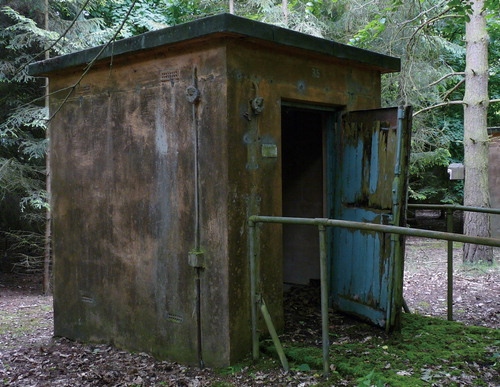
Two ‘special storage sites’ were built at RAF Barnham in Suffolk and RAF Faldingworth in Lincolnshire to store and carry out simple maintenance on Blue Danube.Footnote75 The ‘top site’ store at Barnham, south of Thetford, was operational for just ten years between 1953 and 1963. Blue Danube was made up a small fissile core and a large high-explosive sphere. This combination of radioactive material and high explosives dictated the layout of the site at Barnham. Within the inner compound or ‘danger area’ there were three high explosive storage sheds for the casings and explosives known as the DD Buildings. There were also four sets of individual ‘igloos’ for storage of the plutonium cores distributed around the site, totalling fifty-seven in all. There was a central maintenance building and another much smaller building for maintaining the weapons. The site is built around a circular inner road. The secure area is surrounded by a concrete panel security fence and an outer chain link fence a kilometre long with watch towers at each corner. The ‘free fire’ zone between fences was patrolled by armed guards. In common with other Cold War installations, the bomb store is on a large scale.
Igloos for core storage were simple concrete shelters about 2 metres high fitted with wooden doors, remote alarms, secure door locking and a circular stainless-steel locked safe fitted into the floor (). The cores were light and compact and amenable to manual handling so these storage huts were spread around the site reached by narrow concrete paths. In contrast, the heavy bomb carcase required road access, travelling cranes and mechanical handling devices (although the overhead gantries at the DD sheds were seldom used). Since the bomb casings contained high explosive, lined with their uranium tampers, the three large concrete-framed sheds had side walls that were not bonded into the pillars or the roof. In turn, these sheds were surrounded by earth banks to help contain and deflect any explosion upwards. These sheds were air-conditioned. Typically the bombs were stored in a fishbone pattern on their trailers allowing swift removal in the event of fire.
FIGURE 10. Igloos at RAF Banham Special Storage Unit were used to store the plutonium cores. This is number 35. The large number of igloos may have been designed to intimidate and impress as it is unlikely they were all used either here or at Faldingworth.
Author
New routines were developed for handling the new atomic bomb.Footnote76 There were always two RAF personnel in charge of handling or releasing a nuclear core. To release a core from storage needed an ‘Equipper’ with the combination of the igloo and an ‘Engineer’ with the key to the padlock of the safe inside. They would then walk together with the core to the load carrier. Casings were always transported separately from cores. Again, the two-man principle was always used on the aircraft: the ‘NavRadar’ would release the bomb, but the Captain controlled the bomb release safety lock on the final pin preventing the bomb dropping.
Supply chain: manufacture, assembly and delivery
It is clear the Blue Danube supply chain shifted over time as various manufacturers gained competence and a Royal Ordnance Factory site at Burghfield in Berkshire emerged as an assembly centre, taking over from Chorley.Footnote77 Sections of the weapons were transported to RAF Barnham or RAF Faldingworth for onward deployment to V-bomber airfields in the UK and Cyprus or retained for ‘second strike’ storage. There were many curious features to these covert logistics. For instance, the tail was assembled in Nissen huts at a semi-derelict ROF site at Elstow, south of Bedford. Entrance to this unguarded and unmarked site was concealed behind rusty gates in a hedge off a roundabout on a main road.Footnote78
Conclusion: evolution of a technology
Blue Danube was the first British nuclear deterrent deployed during the Cold War carried by the V-bomber force. Here we consider how the bomb was designed, procured, manufactured, assembled and delivered to airfields and bomb stores, focusing on the practical evolution of the technology. Production of components was widely distributed across the public and private sector in England and Wales.
Focus on the fissile aspects of atomic weapons development means the difficulties of making the whole weapon have been overlooked. It was a struggle to develop and manufacture reliable electronic components, notably the fuzes and firing units. There was an acute shortage of electronics components three years after the weapon was first supplied for operational use. Ironically, deployment was constrained not by lack of fissile material, but by a shortage of simple, clockwork-based time fuzes.
So, development of Blue Danube is a story of paradoxes. Problems with high explosives turned out to be as much a constraint on serviceability as the novel fissile material. Extraction of weapons-grade plutonium was described as a ‘brilliant success’.Footnote79 Yet, HER struggled to design the complicated explosive jacket for Blue Danube.
In broader terms, the story here contradicts conventional accounts of technical development. The ‘linear model’ of development suggests science leads to technology, then to prototypes, on to testing and design and then closes to a reliable final product.Footnote80 In contrast, Blue Danube was an imperative of ‘build first — test later’. Many components were only tested and reliably manufactured after the weapon was delivered. The operational weapon was modified, as if it were a prototype. There were two different ‘priming’ systems and casings during the bomb’s brief history. Production decisions were often based on rules-of-thumb and judgement rather than science and experiment. Blue Danube was more a process of learning than a finished product. It was deployed first and developed afterwards.
Our account shows aspects of atomic weapons technology were distributed across agencies such as the RAF, the RAE, the Ministry of Supply and a range of manufacturing firms. There was a strong interlock between the military needs and the civilian economy. The many innovations needed to bring the weapon into use were spread around the UK. Blue Danube’s practical development was a product of a wider ‘warfare state’ of Cold War Britain, not just the product of a few boffins. In truth, the first atomic bomb was designed in suburban centres and built in ordinary factories down prosaic back streets by regular workers — men and women — in towns across industrial Britain. The atomic bomb was the product of northern industrial towns and the suburbs of southern England as much as the secret citadels of Fort Halstead, Aldermaston and Burghfield.
So, Blue Danube was a provisional deterrent — frequently modified as problems cropped up. Blue Danube continued to evolve after it was designed. In this respect it was also a learning deterrent as the RAF developed new routines and the supply chain learned how to manufacture and maintain nuclear weapons. It was also a half-way house deterrent as those who had been at Los Alamos knew of the possibility of a fission-fusion weapon, an H-bomb.
Above all, Blue Danube — however provisional — was a British deterrent. The weapon was developed and deployed with awesome professionalism and with emphasis on the credibility of the threat it posed. Cheap but practical development of the atomic bomb saved deploying resources elsewhere. As Peter Barker said of ARL’s Drawing Office:
We joked that somewhere there must be a large brilliant team — with boundless resources — doing the ‘real job’, and that we were just a decoy […] it was inconceivable that ARL’s small-scale activity could possibly be a major part of the development of the British Nuclear Deterrent Footnote81
It kept the UK rather forcibly in the great power game and encouraged the Americans to renew cooperation over nuclear secrets. But the triumph of the technology was as much prosaic as scientific.
Notes on contributor
Jonathan Aylen is Senior Lecturer in the Manchester Institute of Innovation Research at the University of Manchester and a member of the Newcomen Society Council.
Acknowledgements
Participants in the design, procurement, manufacture, storage and deployment are the key source of evidence. They are a remarkable group of people who have been generous with time, advice and discussion of artefacts while maintaining an appropriate line between disclosure and secrecy. Some ‘private’ sources preferred not to be acknowledged. Among others, we acknowledge the welcome help of John Allen, Mike Allisstone, Adrian Armishaw, Peter Barlow, Doug Bateman, Brian Burnell, Wayne Cocroft, Tim Crichton, Keith Eldred, Mike Igglesden, Brian Jackson, Keith Julian, ‘Jeff’ Jefford, Reg Milne, Bill Taylor, Bill Tivenan, Mike Watkins, John Weller, Derek Whitehead and at least five unnamed contributors. Key public sources are the National Archives at Kew and the RAF Museum Hendon. In addition, Barnsley Archives, Liverpool Maritime Museum, Mansfield Museum, Sywell Aviation Museum and the Tasker Trust patiently fielded enquiries. The Ministry of Defence and AWE supplied material very efficiently under the Freedom of Information process.
Earlier versions of the paper have been presented to the Defence Electronics History Society, Shrivenham; the Newcomen Society, London; IET, Doncaster and the Nuclear History Conference, Charterhouse.
Notes
1 Peter G. E. F. Jones, ‘Overview of History of UK Strategic Weapons’, in ‘The History of the UK Strategic Deterrent’, The Royal Aeronautical Society Proceedings, Wednesday 17 March 1999, p. 2.2.
2 Richard Rhodes, The Making of the Atomic Bomb (New York: Simon& Schuster, 1986); Chuck Hansen, U.S. Nuclear Weapons: The Secret History (Arlington, Texas: Aerofax, 1988); Margaret Gowing, Britain and Atomic Energy 1939–1945 (London: Macmillan, 1964); Brian Cathcart, Test of Greatness: Britain’s Struggle for the Atom Bomb (London: John Murray, 1994); David Holloway, Stalin and the Bomb: The Soviet Union and Atomic Energy, 1939–1956 (New Haven: Yale University Press, 1994).
3 An exception is John R. Walker, ‘Potential Proliferation Pointers from the Past: Lessons from the British Nuclear Weapons Program, 1952–69’, The Nonproliferation Review, 19.1 (2012), 109–23 emphasizing the difficulty of manufacture and deployment. David J. Hawkings, Keeping the Peace: The Aldermaston Story: A Brief Account of the First Fifty Years of the Home of Britain’s Nuclear Deterrent, the Atomic Weapons Establishment (South Yorkshire: Leo Cooper in association with AWE plc, Aldermaston, 2000) is a cautious introduction.
4 The Ministry of Defence helped at arm’s length through a freedom of information procedure, declassifying a number of documents and photographs for this project. They bear no responsibility for the views expressed here. On the difficulties of researching nuclear weapons, see John R. Walker, British Nuclear Weapons and the Test Ban 1954–1973 (Farnham: Ashgate, 2010), ch. 1.
5 Interviews are relevant since it has been argued that nuclear weapon design is characterized by a high degree of tacit knowledge. But this is true of other advanced technologies, for example aircraft production. See Donald MacKenzie and Graham Spinardi, ‘Tacit Knowledge, Weapons Design, and the Uninvention of Nuclear Weapons’, American Journal of Sociology, 101.1 (July 1995), 44–99, and Walter G. Vincenti, ‘Technological Know-How Without Science: The Innovation of Flush-Riveting in American Airplanes, circa 1930–circa 1950’, Technology and Culture, 25.3 (July 1984), 540–76. Absence of tacit knowledge has not stopped proliferation of nuclear weapons, which suggests practical know-how can be developed in the same way that Britain and the Soviet Union did from 1946.
6 On technology shaped by local practices, see Mikael Hard, ‘Technology as Practice: Local and Global Closure Processes in Diesel-Engine Design’, Social Studies of Science,24.3 (August 1994), 549–85. For technology as evolutionary problem solving, see Jonathan Aylen, ‘Stretch: How Innovation Continues Once Investment is Made’, R&D Management,43.3 (June 2013), 271–87, and R. Ramlogan, A. Mina, G. Tampubolon and J. S. Metcalfe, ‘Networks of Knowledge: The Distributed Nature of Medical Innovation’, Scientometrics, 70.2 (2007), 459–89.
7 David Edgerton says England was above all a technological nation when it came to prosecution of war. Blue Danube was also sourced from Llanishen near Cardiff and Bangor in North Wales. David Edgerton, England and the Aeroplane: Militarism, Modernity and Machines, 2nd edn (London: Penguin, 2013), p. 103.
8 Reg Milne, who looked after the centre section of Blue Danube, discussing ARL Farnborough, 6 August 2013. This individualized problem solving on Blue Danube was very different from the fluid, open and cooperative ‘communities of practice’ that emerged in the development of the Bloodhound guidance system. See Jonathan Aylen, ‘Bloodhound on my Trail: Building the Ferranti Argus Process Control Computer’, International Journal for the History of Engineering & Technology, 82.1 (January 2012), 1–36.
9 Air Commodore Mike Allisstone, former Equipment Officer, 26 February 2014, discussing RAF Barnham.
10 We have not been able to locate this document.
11 See Peter Hennessy, ‘Cabinets and the Bomb’, British Academy Occasional Paper 11 (Oxford: Oxford University Press, 2007), pp. 49–59.
12 Cathcart covers Woolwich and the first Hurricane explosion at Monte Bello Islands.
13 Humphrey Wynn, The RAF Strategic Nuclear Deterrent Forces: Their Origins, Roles and Deployment 1946–1969, a Documentary History (London: HMSO, 1994) covers delivery of the weapon (p. 92) and the trial drop (pp. 97–98 and 170–73).
14 AVIA 65/1114 Ministry of Defence, Defence Research Policy Committee — Atomic Energy Sub-Committee, Supporting Documents 1956, File No. 407/090, 29 November 1956, ‘Serviceability of Blue Danube Mark I and Mark II, Note by the Air Ministry’.
15 Gregg Herken, The Winning Weapon: The Atomic Bomb in the Cold War, 1945–1950 (Princeton, New Jersey: Princeton University Press, 1988 edition), fn. pp. 196–97.
16 Ferenc Szasz, British Scientists and the Manhattan Project: The Los Alamos Years (New York: St Martin’s Press, 1992). Gowing (Britain and Atomic Energy) concludes ‘In so far as “know-how” went the British were well equipped for the postwar construction of atomic bombs’ (p. 267).
17 Wayne D. Cocroft, Fort Halstead, Dunton Green, Sevenoaks, Kent: A Brief Assessment of the Role of Fort Halstead In Britain’s Early Rocket Programmes and The Atomic Bomb Project Research Department Report Series No. 49-2010 (Portsmouth: English Heritage, 2010); Wayne D. Cocroft and Roger J. C. Thomas, Cold War: Building for Nuclear Confrontation 1946–1989, ed. by P. S. Barnwell (Swindon: English Heritage, 2003); Paddy Heazell, Most Secret: The Hidden History of Orford Ness (Stroud: History Press, 2010). On the workings of Fort Halstead, see Lorna Arnold with Katherine Pyne, Britain and the H-Bomb (Basingstoke: Palgrave, 2001), ch. 6.
18 Margaret Gowing with Lorna Arnold, Independence and Deterrence: Britain and Atomic Energy, 1945–1952, 2, Policy Execution (London: Macmillan, 1974), 473.
19 Ibid., p. 369.
20 Professor John Allen, former Senior Scientific Officers, ARL, interview 5 September 2013. The first ‘Fat Man’ bomb dropped at Bikini Atoll in July 1946 missed its target by 2130 feet. See Hansen, p. 31. On the origins of ‘Fat Man’ and why the ‘Thin Man’ gun-type plutonium bomb was abandoned, see Lillian Hoddeson, Paul W. Henriksen, Roger A. Meade, and Catherine L. Westfall, Critical Assembly: A Technical History of Los Alamos During the Oppenheimer Years, 1943–1945 (Cambridge: Cambridge University Press, 1993).
21 Lord Hinton, ‘Atomic Energy’, in A History of Technology, Volume VI, the Twentieth Century c.1900 to c.1950, ed. by Trevor I. Williams (Oxford: Clarendon Press, 1978), pt 1, ch. 10, pp. 223–67 is a frank account of plutonium preparation for the bomb including the choice of a packed column design for the solvent extraction process. Gowing argues secrecy ‘led to serious undervaluation of a very large industrial enterprise which was notable for the magnitude of its tasks and achievements’. Margaret Gowing, Reflections on Atomic Energy History, the Rede Lecture 1978 (Cambridge: Cambridge University Press, 1978), p. 20.
22 Gowing and Arnold, pp. 469–70. The tiny initiator encapsulated in beryllium was called an urchin, because it resembled a sea urchin in size and shape. Code-named ‘kitten’. The case is said to be the size of a golf ball. The ‘urchin’, or initiator, was an intense neutron source at the heart of the core to make sure the chain reaction in the fissile plutonium started at the moment of implosion. The design involves a combination of beryllium and a tiny amount of polonium. The polonium for the initiator was produced by Harwell and Risley (and subsequently Windscale) from irradiated bismuth. Invented by James L. Tuck who went to Los Alamos from Oxford in May 1944. See Hansen, p. 35. Tested at the ‘Operation Totem’ Kittens trials between 26 September and 6 October 1953 at the EMU site in Australia, see J. L. Symonds, A History of British Atomic Tests in Australia (Canberra: Australian Government Publishing Service for Department of Resources and Energy, 1985), pp. 157–59.
23 Drawing No. Arm. 37437/A Issue C. Ostensibly drafted by ‘Tim’ Sims, the Senior Draughtsman of ARL, it was traced (and probably drawn) by Brenda Adams. See RAF Museum, Hendon, AC74/27/2/11/5 Papers relating to Blue Danube, 1953–1955; H/332/ 3103/00002.
24 A note scribbled on a copy of TS 2872 suggests the overall physics package weighed 6200 lb — 2.8 tonnes. ‘Ballistic Casing’. Notes of Meeting held 11 a.m. 11 May 1948 — C.S.A.R. in the Chair. A meeting led by Dr Penney ‘to initiate preliminary investigation into the design of the ballistic casing’ (Private collection, Hampshire).
25 While there is no documentary support, there is convincing private evidence this form of non-destructive testing took place, for instance in building 58 at RAF Barnham Special Storage Site. Informant, 17 October 2013. Norman Skentelbery, Arrows to Atom Bombs: A History of the Ordnance Board, 2nd edn (London: HMSO, 1975) argues ‘the conventional explosives associated with atomic weapons are much more a source of risk than the stable fission material’, p. 175.
26 Shortcomings of the US ‘Fat Man’ Mk III weapon are documented in Hansen, ch. 2, ‘Postwar U.S. Fission Weapons Development’.
27 File AVIA 65/1163 Weapon Principle: Implosion, running from 1 January 1947–31 December 1953 is listed at the NRA as being ‘retained by a government department under Section 3.4 of the Public Records Act, 1958’. Peter Barker, former draughtsman at ARL said ‘The BD project predated the more formalized ‘Systems’ approach to project management […] Hence there was no generally understood overall Project Structure, no known formal definition or specification of Sub-Systems and Interfaces, no generally known Project Reviews […] and so it was always bravely “feeling its way”, hampered by the demands of security which argued for compartmentalization which in turn led to an inefficient project development due to enforced absence of communication between design teams’ (correspondence, 11 August 2014).
28 Arm. 1775/P/SAH/130, HER Working Party ‘C’ Minutes of the first meeting at Fort Halstead on Thursday 28 September 1950 (private collection, Hampshire). It is clear from TS 2872 that work at Farnborough, such as wind-tunnel trials on high-speed bomb release, began before May 1948.
29 Walter G. Vincenti, What Engineers Know and How They Know It — Analytical Studies from Aeronautical History (Baltimore: John Hopkins University Press, 1990).
30 Cathcart, p. 48; Gowing and Arnold, ch. 13 ‘The Men’.
31 AVIA 65/1160, A Technical Review of Bomb, Aircraft, H.E. 10,000 lb., M.C., M.S.1804 (?), /56/D.G. Eng., p. 7, para. 46, 12 December 1956. A view confirmed by Mike Watkins, who said: ‘From my RAF experience I have always felt that the electronics at least could have been designed better […] surprised that lead acid batteries were used for power’ (14 August 2013, email exchange). The official judgement is complicated by the fact that the ‘engineer’ grades were only just being introduced into the Civil Service at the time, so some of the scientists at HER Fort Halstead and many at RAE Farnborough were trained as engineers.
32 Innovation often occurs at the junction of technologies, see John Becklake, ‘The V2 Rocket — a Convergence of Technologies?’, Transactions of the Newcomen Society,67 (1996), 109–23, and Jonathan Aylen, ‘Open Versus Closed Innovation: Development of the Wide Strip Mill for Steel in the USA during the 1920s’, R&D Management, 40.1 (January 2010), 67–80.
33 On the growing role of Farnborough, see AVIA 65/1166 Weapons Programme, file 14 July 1955 to 21 March 1961, and George Hicks, ‘History of RAE and Nuclear Weapons’, ed. by Roy Dommett, Prospero, 2 (Spring 2005), 155–78. For the orthodox role of RAE, see Andrew Nahum, ‘The Royal Aircraft Establishment from 1945 to Concorde’, in Cold War Hot Science: Applied Research in Britain’s Defence Laboratories 1945–1990, ed. by Robert Bud and Philip Gummett (London: Science Museum, 1999), pp. 29–58. Particular thanks are due to Doug Bateman for his research on the early history of ARL (interview 30 May 2013, Farnborough). Doug Bateman argues one reason for RAE’s initial involvement: ‘there was a shortage of scientists and technicians at this time and RAE was long established and had the knowledge and skills’.
34 Sid Hunwicks was, perhaps, a Principal Scientific Officer at this stage in charge of ARL at Farnborough. He had more influence on nuclear policy than his lowly title suggests. He sat on the Director of Air Armaments committee at the Ministry of Aviation which controlled the ‘Nuclear Weapon Programme’. See AVIA 65/1166.
35 Naturally, a radio laboratory needed to be as far away from interference as possible — the story told by John Allen, 5 September 2013. Hicks gives a different interpretation of the ARL name. A second compound was set up for adoption of US nuclear weapons from 1958 in E Hangar, a quarter of a mile away with Dave King in charge. Neither compound is mentioned in a guide to the site, Royal Aircraft Establishment Farnborough, Open Days, Friday 9 June 1961 and Saturday 10 June 1961, Guide to Exhibits (Farnborough: Ministry of Aviation, April 1961). Sid Hunwicks is not listed among the Heads of Department on p. 47 of the Guide.
36 R. I. Vaughan and J. E. Allen,The Effect of High Release Speed on the Design of Blue Danube, AVIA 6/19446 (Royal Aircraft Establishment, Farnborough, RAE, Technical Note No. Arm. 502, December 1952) and interview with J. E. Allen (5 September 2013). The central problem is the bomb had low density and a large surface area, see G. J. Richards, The Ballistics of Blue Danube, AVIA 6/17799 (Royal Aircraft Establishment, Farnborough, RAE, Technical Note No. Arm. 413, by May 1949).
37 The flip-out fins were designed by ‘Cottie’ Cotsworth, then Leading Draughtsman at ARL (Peter Barker, communication 11 August 2014). The duplicate nitrogen bottles were supplied by Walter Kidde. Gas release was initiated by a bomb bay lanyard as the weapon dropped. A blast of gas drove a piston and four pairs of connecting rods which pushed the fins upwards and outward by parallel motion linkage. The fins were locked by driving the connecting rods over dead-centre. The fins were zirconium-aluminium and ran in guide rails which provided the necessary rigidity. The short stub fins at their base were sometimes referred to as ‘glove boxes’ (John Allen, 5 September 2013). The design was modified at least once, especially after a battery door fell off and damaged a fin glove on a trial drop in Australia as the bomb went transonic (interview, Mike Igglesden, 1 October 2013). On the use of lanyards to activate the tail fins, see AIR 10/5677, otherwise AP 1664A, Bomb Handling Equipment, Vol. 1 (Amendments), coverage 1950–59, Bombs and Supply Carriers and Associated Equipment. A three-page amendment dated August 1952 discusses ‘the Mark 2 Lanyard Retracting Unit — a spring operated device for use in conjunction with tail units having retractable fins’. The nylon lanyards were colour coded by length.
38 The retractable fingers for Valiant were developed and tested by Vickers at Weybridge. Vortex formation at the front of the open bomb bay was worse on the Victor with its upwardly sloping underbelly. Interview with Prof. John Allen (5 September 2013 and subsequent conversations).
39 A history of the firm coyly reports after the war ‘Many secret projects were coming the way of the Aircraft Section of the Railway Foundry from the Ministry of Defence. Many of these cannot be recorded due to their classified nature’. The firm’s role in the military-industrial complex belies their benign ‘Thomas the Tank Engine’ image. See Ronald Nelson Redman, The Railway Foundry Leeds, 1839–1969: E. B. Wilson-Hudswell Clarke and Co Ltd (Norwich: Goose and Son, 1972), p. 113.
40 Interview with Brian Burnell, former keeper of drawings, Hudswell Clarke Aircraft Section, London, 9 January 2014. Not one item relevant to Blue Danube remains among the 3000–4000 drawings of supplier Whiteley Electrical Radio Company lodged in Mansfield Museum (search 17 December 2012).
41 Gowing and Arnold, pp. 470–71 suggest the firm assigned two of their best designers to the work. Reg Milne of RAE who was responsible for the centre section of Blue Danube recalls these were R. P. Pedley and L. G. Frise (Milne, interview, Farnborough, 6 August 2013). Mr Pedley, Research Engineer, Percival Aircraft Ltd, received an MBE in 1954. (Also see Wynn interview with ‘George’ Pedley, p. 88.) The firm operated under the name Hunting Percival Aircraft Ltd from 1954. The title Hunting Aircraft Ltd was adopted in 1957. Later work was done as ‘Special Weapons Division of Hunting Aircraft Limited’, later ‘Hunting Engineering Ltd’, abbreviated ‘HEL’ in government documents. A history of the firm is silent on their atomic bomb work. See R. Silvester, Percival and Hunting Aircraft (Luton: R. J. Silvester, c. 1987).
42 Reg Milne, Farnborough (interviews, 6 August 2013 and 8 May 2014 and correspondence). William Freeman& Company Ltd operations were then based at Subaseal Works, Peel Street, Barnsley. Reg Milne says he entered through an unassuming ‘shop front which led into a single storey workshop with roof lights. The workshop must have been two houses wide’. Each air bag was fitted with a schraeder valve.
43 Problems with the fuzes are discussed extensively in Ministry of Supply file AVIA 65/1160, 10,000 lb HE MC bomb: acceptance trials and acceptance for service use, 1951–60.
44 These W/R units were controversial. John Allen claims they were unduly complex with 80 valves in each unit and so prone to failure (conversation, 8 November 2013). Trials to allay concerns that the various fuzes might interfere with one another are reported in A. B. Hillan, ‘The F5 Trial — Performance of W/R Units in the Blue Danube Nose Assembly’, Atomic Weapons Research Establishment, Report No. B21/56 Development of Blue Danube W/R Fuzing System, Part IV/3 (dated February 1957, received 21 January 1957, AWRE Aldermaston, Berks, National Archive ES 2/67).
45 The time fuze was designed by Vernon Rutland at Farnborough. These were duplicated. The two clocks were meant to start together, activated by a bomb bay lanyard. They were worked by a plunger which drove the clockwork on both fuzes. It needed a push to wind up the clockwork. Unfortunately, the dimensions of the ‘cocking mechanism’ were wrong. There was tilt on this mechanism and the fork would move to one side meaning one fuze was wound more than another. The less wound fuze would run down sooner, leading to premature detonation. Reg Milne’s solution was to add a couple of washers to prevent this recurring during the trials at Maralinga. (Reg Milne, 8 May 2014.)
46 The troubleshooting episode is documented in E. T. Jenkins, ‘W/R Unit Production’, Atomic Weapons Research Establishment, Report No. B14/56 Development of Blue Danube W/R Fuzing System, Part III/1 (dated July 1956, received 7 May, 1956, AWRE Aldermaston, Berks, National Archive ES 2/61).
47 This evaluation is given in file AVIA 65/1160, A Technical Review of Bomb, Aircraft, HE 10,000 lb MC, MS.1004/56/D.G.Eng. dated 21 February 1957. Notice the distrust of industry by senior civil servants — this distrust was mutual. See Richard Moore, Nuclear Illusion, Nuclear Reality: Britain, the United States and Nuclear Weapons, 1958–64 (Houndmills, Basingstoke: Palgrave Macmillan, 2010), pp. 246–47.
48 This detonator was patented: US Patent 3,040,660, ‘Electric Initiator with Exploding Bridge Wire’, Lawrence H. Johnston, Los Angeles, Calif., filed 8 November, 1944, published 26 June 1962 assigned to the United States of America as represented by the United States Atomic Energy Commission. It reveals a half a joule provides enough energy to initiate an explosion and this can be ideally provided by a condenser and suggests synchronous operation is possible across detonators to within half a microsecond. Also see Rhodes, p. 655.
49 Cathcart, pp. 70–71. The key task of developing the detonators was led by E. H. Mott and C. M. Bean. On the AWRE production site, see Sarah Newsome and Andrew Williams, Woolwich Common, Woolwich, Greater London: An Assessment of the Historic Environment of Woolwich Common and its Environs, Survey Report, Research Department Report Series no. 098-2009 (Swindon: English Heritage, 2009), pp. 14–17. On detonator operation, see R. J. Baker and C. M. Bean, ‘The “Potting” of Unit 18’, Atomic Weapons Research Establishment, Weapons and Assembly Division, Report No. B7/53 (dated July 1953, AWRE Aldermaston, Berks, National Archives ES 2/7).
50 On John Challens, see Gowing and Arnold, p. 464; Cathcart, pp. 66–70; John Allen interview, 5 September 2013.
51 A key textbook is Ian Alexander D. Lewis and Frank Herbert Wells, Millimicrosecond Pulse Techniques (London: Pergamon Press, 1954). Both authors were at the Atomic Energy Research Establishment, Harwell. Generous help from confidential sources is warmly acknowledged at this point (interviews, 19 December 2012 and 16 January 2013).
52 For example, J. S. Wise, ‘Oscillator Anode Capacitor Assembly’, Atomic Weapons Research Establishment, Report No. B18/56 Development of Blue Danube W/R Fuzing System, Part III/5 (dated June 1956, received 20 April 1956, National Archive ES 2/64). It deals with attempts to reduce the failure rate of condensers built into a component of the W/R ground proximity radar fuze.
53 AVIA 65/1792 History of Nuclear Weapon Production in the UK is an invaluable source.
54 Ibid., p. 7, quote on reliability.
55 AVIA 26/2033; G. W. A. Dummer, Potted Electronic Circuit Techniques, RRE Report no. 3002, Malvern: Ministry of Supply, Radar Research Establishment, May 1954. Also advice from Derek Whitehead (10 September 2013), Fred Axon (15 September 2013) and an amusing but anonymous source (Shrivenham, 17 October 2013).
56 Jenkins.
57 Their surviving drawings attest to a business devoted to loudspeakers, early FM radios, amplifiers, cabinets and Bakelite switches. The firm’s lead product was its range of ‘Stentorian’ loudspeakers. See Whiteley Electrical Radio Company Limited, Mansfield, Notts., spiral-bound publicity pamphlet and catalogue, 1958, Mansfield Museum collection.
58 Heazell, pp. 162–65 discusses trial drops of Blue Danube at Orforness ‘testing […] the trigger mechanisms by sensitive radio telemetry to check that the very elaborate firing relays would work correctly’.
59 These specially designed Extra High Tension condensers were probably made at their Wood Lane Research Centre, London (interview with Dr Keith Julian, former Director of Technology, BICC Cables Ltd, 7 March 2013). Confirmed by National Museums on Merseyside, BICC Collection, Item VI 70 343, ‘The Products of BICC. September 1954’: ‘BICC are prepared, wherever circumstances warrant it, to manufacture special items. For this purpose research into associated problems will be carried out in any of its Research Laboratories’. Even up to the late 1950s capacitors were made of paper soaked in a salt bath and prone to leakage. They are subject to dielectric failure and the metalized paper volatilizes. In short, not very reliable.
60 AVIA 65/1792, 1954 onwards.
61 Ibid., pp. 7–9.
62 Ibid., p. 14.
63 The firm had been founded as Pearson Electrical Company. A scion of the Ferranti family, Dennis de Ferranti took over the firm and pursued a policy of price competition to enlarge sales at the expense of the existing meter cartel. See John F. Wilson, Ferranti: A History, Building a Family Business, 1882–1975 (Lancaster: Carnegie Publishing, 2000), pp. 296–97. The firm moved to Bangor in North Wales, occupying an old shadow factory. A private source indicated their secure component manufacture for Blue Danube ‘was done in an old wooden building out the back’ (interview, 19 December 2012).
64 Cathcart, pp. 136–40, speaks of three competing core designs. The broad configuration of the physics package was due to Klaus Fuchs and permitted In Flight Loading. The detailed local design was developed by John Corner and Herbert Pike and chosen February 1951. This approach lasted for, perhaps, four years. Cathcart wrongly suggests In Flight Loading involved horizontal insertion of the cartridge. This was the layout used by the Blue Peacock atomic mine AVIA 65/2036 Blue Peacock: atomic land mine. Also see David Hawkings, ‘Blue Peacock: The British Army’s Forgotten Weapon’, Discovery (no date, AWE house magazine, privately circulated), pp. 42–43. The version of Blue Danube deployed on the Valiant used vertical In Flight Loading.
65 In Flight Loading on Valiant is covered by Form 555, Ministry of Supply, Report on Examination of Aircraft, To: R.D.Q.B., from D.A.L. Robson, R.T.O. Date: 7 November 1954. Aircraft Valiant B Mk.1, Firm Vickers Armstrongs Ltd. Address: Weybridge, Surrey entitled Installation of 10,000 lb. M.C. Bomb Mk. I in RAF Museum Hendon, file AC74/27/2/11/5 papers relating to Blue Danube, 1953–55; H/332/3103/00002.
66 A trial inert bomb fell off into the bomb bay of a prototype Valiant over Dorking during ballistic trials on 30 July 1952. It was jettisoned over the Thames Estuary with a near miss on a yacht. It was not recovered. Brian Trubshaw was the test pilot at the time (Reg Milne, 6 August 2013; email exchange, Mike Atkins; Brian Trubshaw and Sally Edmonson, Brian Trubshaw: Test Pilot (Stroud: Alan Sutton, 1998), p. 35.
67 John Rowlands played the lead role in the RAF’s adoption of nuclear weapons. Then a Wing-Commander, he was one of ten serving RAF officers seconded to Fort Halstead to ensure the bomb met service specifications. He went on to make a huge contribution to weapon design, servicing, handling, training and safety (Wynn). His remarkable role is overlooked in ‘Air Marshal Sir John Rowlands’, Daily Telegraph, 7 June 2006.
68 Form 555. Blue Bunny had a similar mechanism, see AVIA 65/2036.
69 Frazer-Nash was an idiosyncratic firm which produced gun turrets during the Second World War. This may have recommended them to Air Vice-Marshall A. D. ‘Dizzy’ Davis at the Ministry of Supply. They made two designs for In Flight Loading of Blue Danube. Components were manufactured by Palatine Tool and Engineering located on the A3 Kingston By-Pass at Surbiton in Surrey. The drawing on display at the AWE Educational Collection is a later RAE design by Ben Sykes and Reg Milne. The Frazer-Nash design was subsequently adapted for other use by Peter Barker.
70 The decision to abandon In Flight Loading and alter the design of Blue Danube is anticipated in AVIA 65/1166 Weapons Programme, ‘Notes on a meeting to discuss D.A. Arm’s Nuclear Weapon Programme held at St. Giles Court on 16 July, 1956’, section 2.1 Blue Danube.
71 A cartridge or ‘gauntlet’ known in RAF parlance as a ‘golden goolie’. Among others, former ‘Nav Radar’ John Weller, interview 3 February 2014. The design of this cartridge was developed by Peter Barker, responsible for the appearance of a ‘Russian Spy’ in Figure 4. The plutonium hemi-spheres were gold-plated. Last Minute Loading involved little change to the cartridge assembly, although it was now locked in place manually rather than mechanically. But the Blue Danube casings had to be redesigned to allow access from below rather than from above, and the explosive sphere was inverted.
72 The notion of ‘routines’ evolving over time in response to changed circumstances is due to Richard R. Nelson and Sidney G. Winter, An Evolutionary Theory of Economic Change (Cambridge, Mass: Belknap Press of Harvard University Press, 1982). These routines included a new bombing strategy: no bomber stream or pathfinders, one pre-planned target per aircraft, prior recruitment and training, war of limited duration and blind bombing by radar according to former ‘Nav Radar’ Dave Lingard, ‘Bombing on the tin triangle’, Lecture Newark Air Museum, 20 October 2012.
73 See Wynn, ch. 6.
74 Interview with Squadron Leader Bill Tivenan, Monday 17 February 2014; Wynn, p. 92. Also Michael Hely, ‘Nuclear Weapons Training — Groundcrew’, Royal Air Force Historical Society Journal,26 (2001), 74–80.
75 Keith Eldred, Wayne Cocroft and Mike Allisstone gave considerable advice on Barnham. The special storage site at RAF Barnham is documented in Cocroft and Thomas; Wayne D. Cocroft and D. Gregory, ‘Barnham, St Edmundsbury, Suffolk: RAF Barnham, Special Storage Site. Documentary Analysis of Sources in the National Archives’, Research Department Report 48/2011, Swindon: English Heritage, 2011; also see AIR 29/4157, No. 94 Maintenance Unit RAF Barnham, Air Ministry and Ministry of Defence: Operations Record Books, Miscellaneous Units, 1 October 1957–30 June 1959; and AIR 29/2522, No. 92 MU, Faldingworth, January 1956–December 1960.
76 Interviews with Tivenan, Weller and Allisstone.
77 Production trials began in 1950 and full-scale manufacture took place between 1952 and 1958. Official records suggest a total of 100 active weapons and 20 training weapons were ordered at a cost of £2.2 million by the end of 1962 according to AVIA 65/1792, p. 9 and appendix 2. Estimates vary as to how many were active at any one time. Consensus suggests 57 were deployed and one tested, see Moore, appendix 1, p. 256. There were a large number of trial, ‘practice inerts’ and replacement casings made — well in excess of 250 to judge by component orders. They were used for trials at Orfordness, a programme of drops at Maralinga and for training purposes. A dozen Blue Danube casings were used for Violet Club, a short-lived variant fitted to Vulcans between 1958 and 1959.
78 Interview Allisstone, and Mike Allisstone, ‘Nuclear Weapons and no. 94 MU, RAF Barnham’, Royal Air Force Historical Society Journal, 35 (2005), 54–61. A rare insight into the shifting supply chains is offered by W/R Unit, AWRE, Report B14/56, op. cit., which documents four changes in production routes for ground proximity fuzes between November 1951 and January 1955 when ‘PLO’ — probably Plessey Nucleonics at Stour Road in Northampton — was finally dropped from the supply chain in favour of ‘LPD 4A’ (possibly Borehamwood, North London) and ROF Burghfield. Also email communication, Mike Watkins, 14 August 2013.
79 Hinton, p. 265.
80 On the linear model, see B. Godin, ‘The Linear Model of Innovation: The Historical Construction of an Analytical Framework’, Science, Technology and Human Values,31.6 (2006), 639–67; Philip Scranton, ‘Technology-Led Innovation: The Non-Linearity of US Jet Propulsion Development’, History and Technology,22.4 (December 2006), 337–67.
81 Peter Barker, correspondence, 11 August 2014.
