Abstract
Purpose: This study aimed to determine which treatment parameters of the SonoKnife device can be used to safely and effectively perform non-invasive thermal ablation of subcutaneous tissue.
Methods: A three-dimensional computational layered medium model was constructed to simulate thermal ablation treatment of the SonoKnife device. The acoustic and thermal fields were calculated with the Fast Object-Oriented C++ Ultrasound-Simulator software and a finite difference code, respectively. Subcutaneous tissue was represented as layers of skin, fat and muscle. The simulations were conducted for ultrasound frequencies of 1 or 3.5 MHz. The thermal dose model was used to predict the size and location of the ablated regions. The computer simulations were verified by using the SonoKnife to perform subcutaneous ablations in the neck area of healthy pigs, in vivo. Triphenyltetrazolium chloride viability stain was used to differentiate viable tissue from ablated regions ex vivo.
Results: The simulations for the layered medium model suggest that operating the SonoKnife at frequency of 1 MHz is more effective and safer than 3.5 MHz providing skin cooling is applied prior to ablation. These predictions were in agreement with the results observed in the animal studies. The required sonication time for ablation increased from 50 to 300 s by using 1 MHz.
Conclusion: Our modelling and animal studies suggest that 1 MHz with pretreatment skin cooling are the optimal settings to operate the SonoKnife to safely and effectively perform subcutaneous thermal ablation of porcine skin. More work is needed to optimise skin cooling and define the optimal sonication time.
Introduction
Patients with advanced and recurrent head and neck tumours remain a challenging group facing a poor prognosis Citation[1]. Although adjuvant radiation therapy has been shown to improve overall survival, innovative therapeutic approaches are clearly needed in view of poor outcomes in this high-risk population Citation[2]. Thermal ablation therapy using various energy sources has gained acceptance in the treatment of advanced cancers as well as benign tumours Citation[3–13]. Ablation may enhance the efficacy of ionising radiation therapy and chemotherapy, and potentially reduce the need for surgery, and thus it has the potential to provide significant outcome improvements and lower morbidity rates in patients with advanced tumours Citation[6], Citation[14–16].
In a previous report Citation[17], we introduced the concept of the SonoKnife, a non-invasive, scanned, line-focusing ultrasound thermal therapy device for the ablative treatment of subcutaneous tumours. The SonoKnife was designed for thermal ablation of superficial head and neck tumours and positive lymph nodes that are located not more than 5 cm from the skin and are not much larger than 3 cm in their largest dimension. The SonoKnife transducer was characterised using the open access Fast Object-Oriented C++ Ultrasound Simulator (FOCUS) software Citation[18] in conjunction with finite difference simulation of the thermal field Citation[17]. Thermal simulations were validated by using the SonoKnife transducer to create thermal lesions in porcine liver ex vivo Citation[17]. That study was useful for careful evaluation of the SonoKnife, but since the main purpose of the SonoKnife device is to perform non-invasive thermal ablation of subcutaneous tumours, that study is of limited pre-clinical value.
The purpose of the work reported in this paper was to determine which treatment parameters of the SonoKnife device can be employed to safely and effectively perform non-invasive thermal ablation of subcutaneous neck tissue, in vivo. To that end, we used the FOCUS software and finite difference modelling, as previously reported Citation[17]. However, we modified this modelling approach to simulate the pressure and temperature distribution in a 3-dimensional multi-layer geometry that includes water, skin, fat and muscle. The validity of the simulations was done by comparing the predicted formation and location of the thermally induced lesions with observed pathological outcomes following subcutaneous thermal ablation of neck tissue in live pigs with the SonoKnife device.
Materials and methods
SonoKnife device
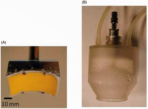
The SonoKnife is a new line-focused ultrasound device concept originally motivated for non-invasive thermal ablation of advanced head and neck tumours and positive lymph nodes. A detailed description and characterisation of the device has been previously published Citation[17]. Briefly, the SonoKnife basic characteristics are an operating frequency of 3.5 or 1 MHz, a radius of curvature (R) of 60 mm, a width (r) of 60 mm and a length (L) of 30 mm. The transducer is made of PZT-8 piezoelectric ceramic material mounted on a custom machined aluminium holder. According to radiation force balance measurements, the electro-acoustic efficiency was 65%. The device was tested with up to 120 We (electric power input) continuous mode for 60 s and up to 200 We at 50% duty cycle. The transducer is enclosed in a plastic housing that circulates cooling-coupling degassed water. The bottom of the housing is made of a thin Mylar membrane for transmission of the sound waves into the target medium. The depth of the line focus is adjustable by moving the transducer relative to the Mylar membrane (along the z direction) via a waterproof shaft O-ring assembly, as shown in .
Acoustic model of the layered medium model
Acoustic simulations for the layered medium model were performed using the open-access FOCUS software Citation[18]. A schematic diagram of the layered medium model is shown in .
Figure 2. Schematic diagrams of a SonoKnife transducer for the layered medium model. (A) A perspective 3D view. (B) Cross-sectional view (y = 0) showing the water, skin, fat and muscle layers which were used in the simulations. Where R = 60 mm, r = 60 mm, L = 30 mm and d = 30 mm.
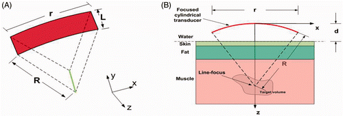
Three tissue layers were considered, namely, skin, fat and muscle. Water was the coupling medium between the transducer and the skin. Neither reflections nor refractions were considered at the water–skin interface. The parameter (R = 60 mm) is the radius of curvature of the cylindrical-section transducer (SonoKnife transducer), (r = 60 mm) is the aperture size or width, (L = 30 mm) is the length of the transducer and (d = 30 mm) is the position of the water–skin interface with respect to the centre of the transducer's radiating area as shown on the bottom panel of .
The thicknesses of the skin, fat, and muscle layers were 2, 8, and 40 mm, respectively. The acoustic and thermal properties employed in the simulations are listed in , and were taken from White et al. Citation[19]. The parameter (f) denotes the excitation frequency, (α) denotes the tissue acoustic attenuation coefficient, and (Ie) denotes the transducer surface intensity or emittance.
Table I. The acoustic and thermal properties that were used for water, skin, fat and muscle in the simulations, taken from White et al. Citation[19].
A planar source pressure distribution in the water layer is first computed using a fast near-field method which is part of FOCUS Citation[18], Citation[20], Citation[21]. Subsequently, this planar source in water was used to compute the 3-dimensional (3D) pressure distributions in the layers of the model using the angular spectrum approach Citation[22]. According to the linear ray theory, when an acoustic wave encounters the boundary between two different media, part of the wave is reflected and part is transmitted. The reflection and transmission coefficients of a plane wave impinging on a planar boundary are well defined Citation[23], Citation[24]. Each layer of the model is considered as a homogeneous region. According to our previous work Citation[17] the 3D pressure distribution in a homogeneous medium can be calculated after the source pressure distribution is obtained. The angular spectra of the pressures at the boundary of medium one () and two (
) are related by:
Citation[24], Citation[25] where
and
are the wave numbers in the x and y directions in the frequency domain,
(density × speed of sound) and
are the acoustic impedances in medium 1 and medium 2, respectively. In Equation 1, the incident (
and transmission (
angles are given by:
where k is the spatial wave number. The pressure
in Equation 1 is considered the source pressure in medium 2, then the 3D pressure distributions in medium 2 can be calculated using the angular spectrum method as we previously described Citation[17].
Thermal model
The Pennes bio-heat transfer equation (BHTE) was used to simulate the temperature fields Citation[26] as follows.where T is the tissue temperature in degrees Celsius, ρ is the tissue density (kg/m3), t is the elapsed time in s, K is the thermal conductivity of tissue (W/m/°C), C is the specific heat of tissue (J/kg/°C), Wb is the blood perfusion rate (kg/m3/s), Cb is the specific heat of blood (J/kg/°C), Ta is the arterial blood temperature (assumed to be 37°C), and Qp is the power deposition per unit volume (W/m3). The operator ∂T/∂t denotes the partial derivative of the temperature with respect to time and
is the Laplace operator. The power deposition Qp for a plane wave is defined as
Citation[27] where c is the speed of sound in the tissue (m/s), and p(x,y,z) is the peak pressure.
The transient BHTE was solved numerically using the finite difference time domain method, as previously used Citation[17]. The BHTE in Equation 3 was discretised as:where i, j, k are the indices of the spatial grid points in the x, y and z directions, respectively, m denotes the index of the time step, Δt is the time step and δ is the uniform spacing between adjacent grid points in the x, y and z directions, respectively. The spatial resolution (
and the time step (
used in the simulations were 0.25 mm and 0.05 s, respectively. The values of
,
, and
in Equation 5 are chosen according to the layer where the spatial grid point is located. Thermal doses in equivalent minutes at 43°C (denoted here as EM43) were computed using the formulation of Sapareto and Dewey Citation[28].
Thermal ablation of porcine skin in vivo
The following procedures were approved by the University of Arkansas for Medical Sciences Institutional Animal Care and Use Committee (IACUC), prior to initiation of the study. Five live pigs of approximately 22.67 Kg in weight were used in this study. The animals were anaesthetised with intramuscular injection of 0.044 mL/Kg body weight pig mix (5 mL Telazol reconstitute with 2.5 mL of 100 mg/mL xylazine and 2.5 mL of ketamine 100 mg/mL). The animals’ neck, abdominal and inner thigh skin was shaved and cleaned, and the animals were transferred to the procedure room where they were intubated and ventilated with 2–3% isoflurane in 1.5 L/min oxygen to provide surgical anaesthesia. The areas of the thermal lesions were marked with permanent ink. A total of 6–8 lesions were made in the neck, abdomen and inner thigh of each animal. An ultrasound gel was placed on the skin to avoid air gaps between the transducer and the skin. Ablations were performed by placing the SonoKnife system on the gel and delivering electric power of 100 W to the crystal, which resulted in acoustic power of 60 W. The focus of the transducer was at 22 mm below the skin surface. The sonications were performed for 50 to 300 s with 100 W electric power. Skin cooling was accomplished by placing an ice pack on the skin surface for 7 min to obtain superficial skin temperature of approximately 8°C, prior to the ablations. Skin damage was documented with digital photographs. One hour following ablation, the animals were euthanised by intravenous injection of Euthasol solution. Immediately following death, a tissue block (∼50 × 50 × 50 mm) containing each of the ablated regions and margins was removed from the animal. These tissue blocks were placed in a −30°C freezer for 2–3 h, and thereafter sliced 2 mm thick in the x–y plane perpendicular to the SonoKnife focal plane (y–z plane). The tissue slices were thawed and stained for viability with 1% triphenyltetrazolium chloride (TTC) solution in phosphate-buffered saline for 1 h at 37°C, as previously described Citation[29].
Results
Simulation for the 3.5 MHz transducer
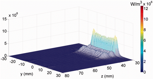
The power deposition distribution calculated for the 3.5 MHz transducer is shown in . The peak power deposition has a higher (30-fold) value in the skin region (x = 0, z = 30) than in the fat region.
Figure 3. The power deposition distribution calculated for the 3.5 MHz transducer in the skin region (at x = 0). The skin surface is at z = 30 mm.
In , we present the associated calculated temperature distribution after sonication for 30 s without and with skin cooling; and , respectively. The solid contour lines demarcate regions within this plane where the calculated thermal doses exceeded 240 EM43 (thermal dose contours). For skin cooling, the initial conditions at the skin surface (z = 30) was 8°C. During ablation, the maximum temperature was 89.5°C without skin cooling (A) and 70°C with pre-cooling of the skin (B). The thermal dose contours suggest that thermal ablation will occur in two separate ablated regions. One ablated region is at the focal plane region (red arrow) and another is within the skin region (brown arrow). Thus, the simulations predict that skin burns will occur for the 3.5 MHz SonoKnife transducer without and with pre-cooling of the treated skin.
Figure 4. Simulated temperature distribution and thermal dose contours (inner contour > 240 EM 43°C) for the 3.5 MHz transducer, (A) without skin cooling and (B) with skin pre-cooling after 30 seconds of sonication, with transducer emittance of 3 W/cm2. The skin surface is at z = 30 mm. The skin temperature prior to ablation was 8°C. The red and brown arrows point to the predicted ablated regions in the focal plane and skin areas, respectively.

Simulation results for the 1 MHz transducer
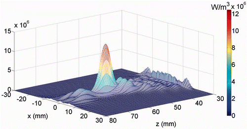
The simulated power distributions for a 1.0 MHz SonoKnife are plotted in . At this lower frequency the peak power was shifted by 35 mm in the z direction (towards the muscle and fat region), in comparison to .
Figure 5. The power deposition distribution calculated for the 1 MHz transducer in the skin region (at x = 0). The skin surface is at z = 30 mm.
The associated calculated temperature distribution and thermal dose contours after sonication for 30 s without and with surface cooling are shown in and , respectively. For skin cooling, the initial condition at the skin surface (z = 30) was 8°C. During ablation, the maximum temperature at the focal plane (z = 60 mm) was 65°C in both cases. However, the maximum temperature on the skin surface (z = 30 mm) was 55°C without cooling (A) and 30°C with pre-cooling of the skin (B). Thus, our computer simulations suggest that we can induce subcutaneous thermal ablation without skin damage by using a 1 MHz SonoKnife transducer with skin cooling.
Figure 6. Simulated temperature distribution and thermal dose contours (inner contour > 240EM 43 C) for the 1.0 MHz transducer, (A) without cooling and (B) with skin pre-cooling, after 30 seconds of sonication, with transducer emittance of 3 W/cm2. The skin surface is at z = 30 mm. The skin temperature prior to ablation was 8°C.

Animal studies
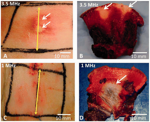
Skin burns were observed immediately following ablation when using a 3.5 MHz SonoKnife transducer that delivered an acoustic power of 60 W for 50 s, in all the anatomical regions (neck, abdomen and inner thigh). In we present results from treatments in the neck region, this figure is an accurate representation of our results. In this particular experiment, cooling of the skin was used, and the focus was set to be at 22 mm below the skin surface. A skin burn is clearly seen on the skin (A) and in cross-section image where the TTC did not stain the regions that were ablated (white areas), next to the epidermal/dermal junction (B). In contrast to these observations, no skin burns were seen following ablation with a 1 MHz SonoKnife transducer that delivered an acoustic power of 60 W for 300 s (C). However, a clear lesion is seen in the cross-sectional slice, which is the white region that was not stained with the TTC (D).
Figure 7. The skin of live pigs after thermal ablation with the SonoKnife using 100 W input power with either 3.5 or 1 MHz transducer for 50 and 300 seconds continuous sonication respectively. Skin cooling was done in both cases by placing an ice pack on the skin surface. The skin temperature was 8°C. (A) Skin burns (pointed with white arrows) seen immediately after ablation with 3.5 MHz SonoKnife transducer. (B) Skin burns in cross section after TTC staining (white arrows point towards the whitish non viable tissue). (C) The skin surface after therapy with 1 MHz SonoKnife transducer, where no skin burns were seen. (D) A subcutaneous thermal lesion is seen in cross section after TTC staining (white arrow points towards the non viable whitish tissue). The yellow double-headed arrow marks the centre of the Sonoknife transducer (along y axis).
Discussion and conclusions
The Sonoknife was designed for non-invasive thermal ablation of tumours and involved lymph nodes that are located within 50 mm from the skin surface and are no more than 30 mm in diameter. The large focal area (10 × 30 mm) of the SonoKnife enables the treatment of a substantial area of tissue in a single sonication Citation[17]. However, the relatively high attenuation of the skin and the proximity of the focal area to the epidermal/dermal junction could result in superficial skin burns. One possible option to reduce the risk of skin burns is to pre-cool the skin to a low temperature (e.g. 8°C). Another option is to reduce the frequency of the SonoKnife transducer, which will reduce the absorption in the skin, and the overall power deposition to target tissue. The mathematical modelling approach enabled us to test the effect of each of the above possibilities and their combination on the safety and efficacy of thermal ablation of subcutaneous tissue with the SonoKnife device.
The simulations were performed for transducer frequency of either 1 or 3.5 MHz and assumed initial skin temperature of 8°C. Using these parameters, the simulations suggest that skin burns can occur by using a SonoKnife transducer of 3.5 MHz without cooling and these burns cannot be avoided, even when skin cooling is applied prior to ablation. Our animal experiments confirmed these predictions, where the skin was pre-cooled to a temperature of 8°C. We observed that skin cooling does not prevent skin burns when a 3.5 MHz transducer is used to create subcutaneous thermally induced lesions. At that frequency the high attenuation of the skin (see Table I) leads to high energy deposition in the surface layer with damage to the skin at the epidermal/dermal junction, as shown in and . Thus, both the mathematical simulations and the animal studies suggest that a SonoKnife transducer with 3.5 MHz frequency may not be appropriate for the treatment of subcutaneous tumours. We note, however, that human skin is thinner than porcine skin and may have lower attenuation to the same SonoKnife frequency, so it is plausible that this frequency (3.5 MHz) maybe safe for humans.
These simulations and animal studies suggest that a 1 MHz SonoKnife transducer can be used safely and effectively to ablate subcutaneous tumours provided that skin cooling (to 8°C) is applied prior to the ablation therapy. Local skin cooling with ice could be safe in clinical practice, as a similar approach is used prior to laser therapy Citation[30], Citation[31]. Of note, the increased safety that is achieved by lowering the transducer frequency (i.e. power deposition) also required the treatment time to lengthen from 50 s to 300 s (5 min). A 5-min therapy could be acceptable in clinical settings, since a typical ablation treatment with focus ultrasound takes at least 20 min Citation[32]. In this study, however, we did not research the optimal treatment time. Additional work is needed to identify the optimal sonication time/power settings for the SonoKnife with 1 MHz transducers.
Our results demonstrate that the layered medium model is valid and can be used to support the design of SonoKnife transducers for the treatment of subcutaneous tumours. The data reported in this paper can guide the design of a SonoKnife device for future clinical studies. In theory the SonoKnife can be used to treat tumours that are deeper than 3 cm (see Chen et al. [17]. This study is only the first step necessary to define the practical parameters to safely treat subcutaneous tumours. Additional engineering work is required before this technology will be ready for clinical use. Additionally, more reliable active skin cooling attachments must be developed and tested before clinical studies can be considered with the SonoKnife device.
Acknowledgements
The authors would like to thank Robert J. McGough from Michigan State University for making the FOCUS simulation package available to us as an open source.
Declaration of interest: This work was supported by a NIH/NCI grant RC1 CA147697 (PI: EGM). We gratefully acknowledge general research support from the Central Arkansas Radiation Therapy Institute (CARTI). Principal Investigator was Eduardo G. Moros. The authors alone are responsible for the content and writing of the paper.
References
- Chin D, Boyle GM, Porceddu S, Theile DR, Parsons PG, Coman WB. Head and neck cancer: Past, present and future. Expert Rev Anticancer Ther 2006; 6: 1111–1118
- Lavaf A, Genden EM, Cesaretti JA, Packer S, Kao J. Adjuvant radiotherapy improves overall survival for patients with lymph node-positive head and neck squamous cell carcinoma. Cancer 2008; 112: 535–543
- Casaril A, Abu Hilal M, Harb A, Campagnaro T, Mansueto G, Nicoli N. The safety of radiofrequency thermal ablation in the treatment of liver malignancies. Eur J Surg Oncol 2008; 34: 668–672
- Margreiter M, Marberger M. Focal therapy and imaging in prostate and kidney cancer: High-intensity focused ultrasound ablation of small renal tumors. J Endourol 2010; 24: 745–748
- Esnault O, Franc B, Chapelon JY. Localized ablation of thyroid tissue by high-intensity focused ultrasound: Improvement of noninvasive tissue necrosis methods. Thyroid 2009; 19: 1085–1091
- Timmerman RD, Bizekis CS, Pass HI, Fong Y, Dupuy DE, Dawson LA, et al. Local surgical, ablative, and radiation treatment of metastases. CA Cancer J Clin 2009; 59: 145–170
- Nguyen CT, Campbell SC. Salvage of local recurrence after primary thermal ablation for small renal masses. Expert Rev Anticancer Ther 2008; 8: 1899–1905
- Crocetti L, Lencioni R. Thermal ablation of hepatocellular carcinoma. Cancer Imaging 2008; 8: 19–26
- Taran FA, Tempany CM, Regan L, Inbar Y, Revel A, Stewart EA. Magnetic resonance-guided focused ultrasound (MRgFUS) compared with abdominal hysterectomy for treatment of uterine leiomyomas. Ultrasound Obstet Gynecol 2009; 34: 572–578
- Shen SH, Fennessy F, McDannold N, Jolesz F, Tempany C. Image-guided thermal therapy of uterine fibroids. Semin Ultrasound CT MR 2009; 30: 91–104
- Hynynen K. MRI-guided focused ultrasound treatments. Ultrasonics 2010; 50: 221–229
- Carrafiello G, Lagana D, Mangini M, Fontana F, Dionigi G, Boni L, et al. Microwave tumors ablation: Principles, clinical applications and review of preliminary experiences. Int J Surg 2008; 6: S65–69
- Gough-Palmer AL, Gedroyc WM. Laser ablation of hepatocellular carcinoma – A review. World J Gastroenterol 2008; 14: 7170–7174
- Penagaricano JA, Moros E, Novak P, Yan Y, Corry P. Feasibility of concurrent treatment with the scanning ultrasound reflector linear array system (SURLAS) and the helical tomotherapy system. Int J Hyperthermia 2008; 24: 377–388
- Kampinga HH. Cell biological effects of hyperthermia alone or combined with radiation or drugs: A short introduction to newcomers in the field. Int J Hyperthermia 2006; 22: 191–196
- Grieco CA, Simon CJ, Mayo-Smith WW, DiPetrillo TA, Ready NE, Dupuy DE. Percutaneous image-guided thermal ablation and radiation therapy: Outcomes of combined treatment for 41 patients with inoperable stage I/II non-small-cell lung cancer. J Vasc Interv Radiol 2006; 17: 1117–1124
- Chen D, Xia R, Chen X, Shafirstein G, Corry PM, Griffin RJ, et al. SonoKnife: Feasibility of a line-focused ultrasound device for thermal ablation therapy. Med Phys 2011; 38: 4372–4385
- McGough RJ, FOCUS: Fast Object-Oriented C++ Ultrasound Simulator. Michigan State University, 2010. http://www.egr.msu.edu/focus-ultrasound
- White WM, Makin IR, Slayton MH, Barthe PG, Gliklich R. Selective transcutaneous delivery of energy to porcine soft tissues using intense ultrasound (IUS). Lasers Surg Med 2008; 40: 67–75
- Chen D, Kelly JF, McGough RJ. A fast near-field method for calculations of time-harmonic and transient pressures produced by triangular pistons. J Acoust Soc Am 2006; 120: 2450–2459
- McGough RJ. Rapid calculations of time-harmonic nearfield pressures produced by rectangular pistons. J Acoust Soc Am 2004; 115: 1934–1941
- Williams GE. Fourier Acoustics: Sound Radiation and Nearfield Acoustical Holography. Academic Press, London 1999
- Kinsler LE, Frey AR, Coppens AB, Sanders JV. Fundamentals of Acoustics, fourth edition. Wiley, NewYork 2000
- Xiaozheng Z. Ultrasound phased array simulations for hyperthermia. Michigan State University, Dissertation 2008
- Clement GT, Hynynen K. Forward planar projection through layered media. IEEE Trans Ultrason Ferroelectr Freq Control 2003; 50: 1689–1698
- Pennes HH. Analysis of tissue and arterial blood temperature in the resting human forearm. J Appl Physiol 1948; 1: 93–102
- Cavicchi TJ, O’Brien WD, Jr. Heat generated by ultrasound in an absorbing medium. J Acoust Soc Am 1984; 76: 1244–1245
- Sapareto SA, Dewey WC. Thermal dose determination in cancer therapy. Int J Radiat Oncol Biol Phys 1984; 10: 787–800
- Shafirstein G, Novak P, Moros EG, Siegel E, Hennings L, Kaufmann Y, et al. Conductive interstitial thermal therapy device for surgical margin ablation: In vivo verification of a theoretical model. Int J Hyperthermia 2007; 23: 477–492
- Vlachakis I, Gardikis S, Michailoudi E, Charissis G. Treatment of hemangiomas in children using a Nd:YAG laser in conjunction with ice cooling of the epidermis: Techniques and results. BMC Pediatr 2003; 3: 2–6
- Hohenleutner U, Walther T, Wenig M, Baumler W, Landthaler M. Leg telangiectasia treatment with a 1.5 ms pulsed dye laser, ice cube cooling of the skin and 595 vs 600 nm: Preliminary results. Lasers Surg Med 1998; 23: 72–78
- Siddiqui K, Chopra R, Vedula S, Sugar L, Haider M, Boyes A, et al. MRI-guided transurethral ultrasound therapy of the prostate gland using real-time thermal mapping: Initial studies. Urology 2010; 76: 1506–1511
