Abstract
Purpose: The aim of this study was to assess the feasibility of a hybrid ablative technique based on applying electroporation (EP) pulses just before conducting radiofrequency ablation (RFA). The rationale was that the EP-induced reduction in blood perfusion could be sufficient to reduce the thermal sink effect and hence to increase the coagulation volume in comparison to that created exclusively by RFA.
Materials and methods: A modelling study and in vivo experimental study were used. A Cool-tip RF applicator was used both for EP and RFA.
Results: Overall, the results did not show any synergy effect from using the hybrid technique. Applying EP pulses prior to RFA did not increase the coagulation zone obtained and the lesions were almost identical. Additional computer simulations provided an explanation for this; the effect of reducing blood perfusion by thermal damage during RFA completely masks the effect of reducing blood perfusion by EP. This is because both thermal damage and EP affect the same zone, i.e. the tissue around the electrode.
Conclusions: Our computer modelling and in vivo experimental findings suggest that the combination of EP and RFA with monopolar applicators does not provide an additional benefit over the use of RFA alone.
Introduction
Radiofrequency (RF) ablation (RFA) is a minimally invasive ablative technique used to treat certain tumours [Citation1,Citation2] by using RF current (≈500 kHz) to produce a coagulation zone characterised by a thermal lesion which destroys the target tissue by necrosis. The coagulation zone is defined as the zone containing irreversibly damaged tissue, i.e. with temperatures above 50 °C [Citation3]. In order to treat large tumours, therefore, the RF applicator should be able to create large coagulation zones. One of the most important factors limiting coagulation zone size is blood perfusion through the capillaries, which causes a thermal sink effect [Citation4]. In fact, the coagulation zone can be increased during RFA when blood flow is reduced by clamping the organ’s main artery [Citation5]. Unfortunately, this manoeuvre produces a generalised ischaemia in the organ and hence is not a satisfactory solution.
In electroporation (EP) cell membrane permeability to ions and macromolecules is increased after exposing the cell to high electric field short pulses. According to the number of pulses, their magnitude, duration and other factors, the permeability will be either temporary and will not compromise cell viability (i.e. reversible electroporation) or will be permanent, or too intense, so that cell homeostasis will be severely disrupted and the cell will end up dying by necrotic or apoptotic processes (i.e. irreversible electroporation). Both reversible and irreversible EP modes have important applications in biotechnology and medicine. For instance, reversible EP is now a routine technique in microbiology labs for in vitro gene transfection. During the last fifteen years, reversible EP has been applied experimentally and clinically to living tissues for in vivo gene therapy (electrogenetherapy) and for enhancing the penetration of anti-cancer drugs into cancer cells (electrochemotherapy) [Citation6]. More recently, irreversible EP has been proposed and demonstrated as a minimally invasive tissue ablation method [Citation7].
An interesting outcome of performing EP in living tissues is the immediate local reduction in blood flow. Blood perfusion has been reduced by about 70% for example in subcutaneous tumours a few seconds after receiving eight 100 μs pulses at a magnitude of 130 000 V/m and a repetition rate of 1 Hz [Citation8]. This reduction is related to microvascular occlusion of capillaries and arterioles and in some cases reverts in a matter of minutes or hours [Citation9,Citation10]. Two main explanations have been hypothesised for this phenomenon: (1) a sympathetically mediated constriction of smooth vascular musculature would explain the first rapid phase of blood flow reduction and (2) damage to the endothelial monolayer by EP would cause liquid extravasation, which would increase parenchyma pressure, collapse vessels and thus cause blood occlusion [Citation8].
With these results in mind, we hypothesised that the reduced blood perfusion caused by EP pulses applied prior to RFA could be sufficient to reduce the thermal sink effect, and hence to increase coagulation volume more than that created solely by RFA. In order to assess the feasibility of this hybrid ablative technique, we first planned a theoretical modelling study in which a Cool-tip RF applicator (Valleylab, Boulder, CO) was used to apply both EP pulses and RF power to hepatic tissue. We then conducted an experimental study based on an in vivo model to validate the theoretical results obtained.
Materials and methods
Theoretical modelling: General characteristics
The theoretical model was based on a coupled EP + RF problem, each part of which was, in turn, based on a coupled electric thermal problem and solved numerically using the finite element method (FEM) by means of COMSOL Multiphysics 3.5a (COMSOL, Burlington, MA). The geometry and dimensions of the theoretical model are shown in . The problem presented axial symmetry, so that a 2D analysis could be conducted. The model included three different materials: plastic partially covering the electrode, a metallic electrode, and hepatic tissue. The values of the characteristics of these materials are given in [Citation11–14]. It should be noted that the electrical conductivity value for hepatic tissue corresponds to the RF problem; the conductivity value for the EP problem is somewhat lower (see the following subsection). The dispersive electrode was modelled as an electrical condition on boundaries at a distance from the active electrode.
Figure 1. Geometry of the two-dimensional model used in the theoretical study (out of scale, dimensions in mm). The domain is divided into three zones: plastic portion of the electrode, metallic electrode and hepatic tissue.
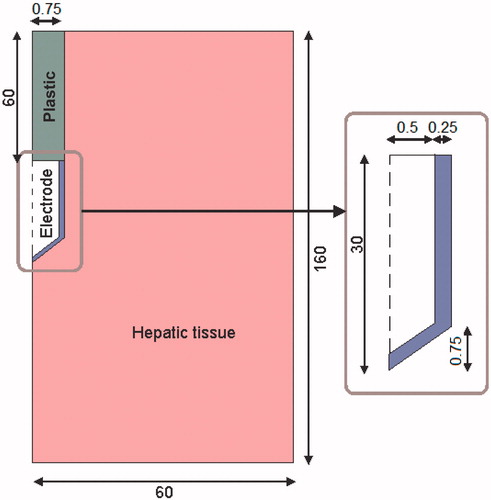
Table I. Characteristics of the materials used in the theoretical model [Citation11–Citation14].
Theoretical modelling: EP problem
As described below in the RF problem, the electric field in the tissue due to an EP pulse was computed by means of the FEM tool. The ‘quasi-statics/electric’ application mode of the AC/DC module of COMSOL was employed to obtain the electric field when a pulse of 2000 V was applied between the active electrode and dispersive electrode ().
Non-linear resistive behaviour was assumed for the hepatic tissue (Gompertz sigmoid expression, Equation (1)) to model the increase in tissue electrical conductivity during pulse delivery due to EP [Citation15].
It has recently been shown that modelling this effect significantly improves the accuracy of these simulations [Citation16,Citation17]. DC conductivity at low electric field magnitudes (σ0 = 0.08 S/m) and DC conductivity at very high fields (σMAX = 0.31 S/m = σ0 + Δσ) were obtained from [Citation15]. The sigmoid behaviour and the parameters that determine its shape were adjusted from data in Sel et al. [Citation18]. Gompertz sigmoid function was chosen instead of other possible sigmoid functions, such as the sigmoid expression employed in Sel et al. [Citation18], because its shape parameters are easily identifiable in the expression.
The simulated time was not relevant, since no time-dependent properties or effects were modelled. Nevertheless, for the sake of conceptual consistency, the electric field for computing perfusion was recorded at the end of a pulse of 100 μs. This pulse included a rise ramp of 5 μs to facilitate the convergence of the solution required by the iterative process, in which the electric field distribution depends on the conductivity of the previous step and vice versa.
Prior to the RF problem, the computed electric field magnitude at the end of the 100 μs was scaled according to the following expression (Equation 2) to obtain the reduction in blood flow:
where α represents the relative blood perfusion level, 1 indicates the normal perfusion level (i.e. before EP or in tissue zones in which the electric field magnitude is insufficient to cause any blood flow disturbance), and 0 represents the complete disruption of blood flow. Note that a linear decrease in blood perfusion was modelled between two electric field values (75 000 V/m and 130 000 V/m) and that the minimum relative blood perfusion level achievable by EP is 0.3.
The above blood perfusion expression was obtained by approximation of data in Sersa et al. [Citation8], which corresponds to experimental measurements in subcutaneous tumours after a sequence of eight 100 μs pulses. These original data together with the function used to model them (α) are depicted in .
Figure 2. Relative blood perfusion after delivery of 8 pulses of 100 μs at 1 Hz. The experimental data was obtained from [Citation8]. The model corresponds to equation (2).
![Figure 2. Relative blood perfusion after delivery of 8 pulses of 100 μs at 1 Hz. The experimental data was obtained from [Citation8]. The model corresponds to equation (2).](/cms/asset/30898ebd-24a3-4392-b095-c7a7c2b22e24/ihyt_a_777854_f0002_b.jpg)
Quantitative liver data is not presently available, but as similar quantitative data was obtained for skeletal muscle [Citation19] and qualitative observations on liver also indicate a drastic blood perfusion reduction in equivalent conditions [Citation9], which suggests that the above-described model is sufficiently accurate for the purposes of this study.
Theoretical modelling: RF problem
The governing equation for the thermal problem was the Pennes bioheat equation [Citation20]. To incorporate the phase change [Citation21–22] into this equation we used the enthalpy method [Citation23]:
where ρ was density of tissue, h enthalpy, T temperature, t time, k thermal conductivity, q the heat source produced by RF power, Qm the metabolic heat generation (not considered in RF ablation), and Qp was heat loss from blood perfusion.
For biological tissues, enthalpy is related to tissue temperature by the following expression [Citation24]:
where ρi and ci were tissue density and specific heat of normal tissue (i = l) and the post-phase-change tissue (i = g), respectively, hfg was the product of water latent heat of vaporisation and water density at 100 °C and C was tissue water content inside the liver (68%) [Citation25].
The heat source by RF power q (Joule losses) was given by q = JE, where J is current density and E is electric field strength. Both were obtained from the electrical problem, in which we used the Laplace equation ▿2V = 0 as governing equation, V being the voltage. The electric field was calculated by means of E = − ▿V and J using Ohm’s law (J = σE), where σ is the electrical conductivity. We used a quasi-static approach, i.e. the tissues were considered as purely resistive [Citation26] due to the value of the frequencies used in RF (≈500 kHz) and for the geometric area of interest (electrical power is deposited in a very small zone close the electrode). We considered temperature-dependent functions for the electrical and thermal conductivity, σ and k [Citation26]; σ grew exponentially +1.5%/ °C up to 100 °C [Citation21], between 99 and 100 °C was kept constant and then σ decreased linearly four orders for five degrees (i.e. up to 105 °C) [Citation23,Citation27]. For k we considered linear growth of 0.0015/ °C up to 100 °C, after which k was kept constant [Citation23]. The term Qp was obtained from Equation (5).
where ρb was density of blood (1000 kg/m3) [Citation28], cb specific heat of blood (4,180 J/Kg K) [Citation27], Tb blood temperature (37 °C), ωb blood perfusion coefficient (6.4 × 10⁻³s−1) [Citation28], α relative blood perfusion which varied between 0 and 1 obtained in the EP problem, and β was a coefficient which took the values of 0 and 1, depending on the value of the local thermal damage Ω: β = 0 for Ω ≥ 1, and β = 1 for Ω < 1[Citation29]. Ω was assessed by the Arrhenius damage model [Citation30], which associates temperature with exposure time using a first-order kinetics relationship:
where R was the universal gas constant, A was a frequency factor and ΔE was the activation energy for the irreversible damage reaction. The parameters A and ΔE were dependent on tissue type; for liver we used those proposed by Jacques et al. [Citation31]: A = 7.39 × 1039 s−1 and ΔE = 2.577 × 10⁵ J/mol). We employed two thermal damage contours to compute the lesion dimension contours, which correspond to a damage integral (Ω) of 1 and 4.6 (63% and 99% probability of cell death respectively) [Citation29].
Electrical boundary conditions were: zero current density in the transverse direction to the symmetry axis and inside the electrode. Zero voltage was set in the dispersive electrode. A voltage of 80 V was applied in the active electrode. Thermal boundary conditions were null thermal flux in the transversal direction to the symmetry axis and constant temperature of 37 °C in the dispersive electrode. Initial temperature of the tissue was considered to be 37 °C. The liquid circulating inside the electrode produced a cooling effect modelled by means of a thermal convection coefficient h with a value of 6668 W/K m2 and a coolant temperature of 10 °C. The value of h was calculated by considering a length of 30 mm and a flow rate of 45 mL/min through an area of 3.93 × 10⁻⁷ m2, which is equivalent to half of the cross section of the inner diameter of the electrode (see ).
The mesh used was heterogeneous, with a finer mesh size at the electrode–tissue interface, where the highest gradient was expected. The size of the finer mesh was estimated by a convergence test. We used the value of the maximum temperature (Tmax) reached in the liver at roll-off time (at which tissue impedance was 30 Ω higher than the initial [Citation13]) as a control parameter in these analyses. When there was a difference of less than 0.5% in the control parameter between simulations, we considered the former mesh size as appropriate. Analogously, we used a value of 1 for the time-step obtained from a similar convergence test scheme.
A pulsed RF protocol was used for energy delivery, consisting of the application of 80 V up to roll-off time, after which energy was not applied for 15 s and then 80 V was again applied until the next roll-off. This protocol was followed for 12 min and implemented by the connection between COMSOL and MATLAB.
Experimental setting
A total of 12 procedures (one in each hepatic lobe) were performed on the liver of three female Landrace pigs under general anaesthesia through midline laparotomy. The procedure was approved by the Ethical Commission of the Universitat Autònoma de Barcelona (authorisation numbers DAAM 6267 and CEEAH 1256). In each animal, in the first lobe RFA only was performed, in the second an EP protocol only, and in the third and fourth the EP + RF procedure was applied. RFA was conducted immediately after EP. In both EP and RFA a single Cool-tip applicator with 3-cm long electrode (Valleylab) was applied parallel to the suprahepatic main vein of each lobe.
EP pulses were applied in a monopolar arrangement between the Cool-tip applicator electrode and a single dispersive electrode positioned on the interscapular area. A custom-made generator was used to deliver eight square-wave pulses with duration of 100 µs and a magnitude of 2000 V at a repetition frequency of 1 Hz. A high voltage probe (P5100, Tektronix, Beaverton, OR) and a clamp-on current probe (A622, Tektronix) were used in combination with a digital oscilloscope (DS01014A, Agilent, Santa Clara, CA) to measure voltage and current signals respectively, to ensure proper application of the pulses.
RFA was also conducted in a monopolar mode between the applicator and the dispersive electrode, but in this case the electrode was internally cooled by a Watson Marlow peristaltic pump (Wilmington, MA), which delivered 0 °C saline at 20 mL/min, beginning 2 min prior to RF power deposition. RF power was applied with a CC-3 generator (Radionics, Burlington, MA) using a pulsed algorithm based on an impedance control mode for 12 min, as employed in clinical use. In each animal, when the four ablations were complete the animal was euthanised using an IV dose of sodium pentobarbital. In any case, more than 1 h elapsed from any thermal injury to euthanasia.
We immediately conducted a macroscopic assessment of the coagulations as follows: the liver was cut into 1-cm slices perpendicular to the applicator axis in order to measure macroscopically axial and transverse diameters of the coagulation zone. All the measurements were based on the central ‘white zone’ induced by thermal therapies, avoiding the red area of hyperaemia [Citation32]. Mean values of maximum and minimum diameters were compared through the groups using Mann-Whitney’s U-test. Differences in variables were considered to be significant at a threshold of p < 0.05. Statistical analyses were performed with statistical software (version 19.0, SPSS, Chicago, IL).
Results
Numerical results
As a result of the EP pulse application the tissue perfusion changed according to the relative blood perfusion level (α). shows the electric field distribution joint with the resulting blood perfusion at the end of the EP pulse. In the RF problem we first simulated two cases and then compared their results: the EP + RF procedure (case 1) and RFA alone (case 2). ) show voltage and impedance evolution for case 1. The EP pulse application interval (7 s) is insignificant compared to the 12-min interval in RFA, and hence the EP period is not plotted. The first roll-off (sudden impedance rise) was reached at 60 s. The subsequent roll-offs were observed 30 s later and the time between roll-offs was decreasing linearly to the fourth roll-off when the subsequent roll-offs were reached more or less periodically with an interval of ≈23 s. Note that after every roll-off there was a 15-s period in which almost no voltage was applied. shows the temperature distributions and the thermal damage contour (Ω = 1 and Ω = 4.6, black lines) at the end of RFA (12 min) in case 1. shows the transverse diameter of the thermal lesion for both thermal damage contours. The maximum temperature reached in the tissue was 110 °C. In we observed the temperature distribution in case 1 at the end of the RF application (12 min) and the contour lines corresponding to the blood perfusion level (α) obtained from the EP problem.
Figure 3. Distribution of the relative blood perfusion (α) and the electric field (V/m) at the end of the application of the EP pulse.
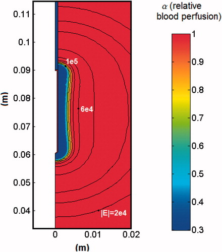
Figure 4. Voltage (A) and impedance (B) evolution in the computer simulations of EP + 12-min RF ablation case without plotting the EP period. (C) Impedance evolution in the computer simulations of RF ablation alone.

Figure 5. Temperature distributions after 12 min RF ablation and previous application of EP pulses. The black lines represent the thermal damage lesion which corresponds to Ω = 1 and Ω = 4.6. The values of the transverse lesion diameters (in cm) are shown for both contours of thermal damage.
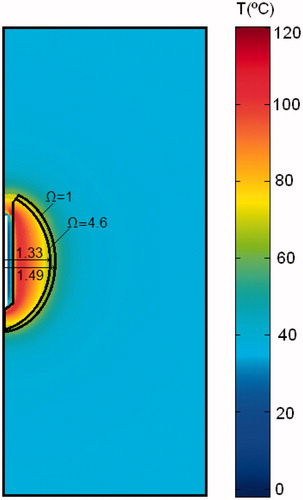
Figure 6. Temperature distributions after 12 min of RF ablation and previous application of EP pulses joint with the blood perfusion level (α) map.
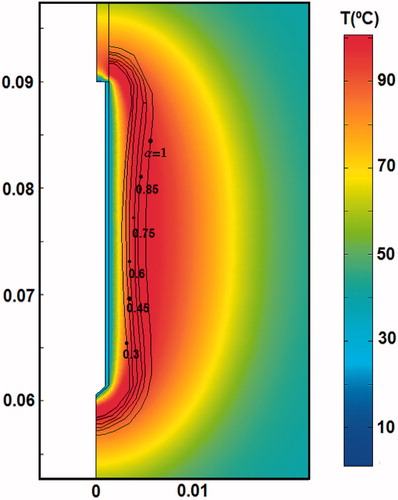
Table II. Transverse diameter of experimental and theoretical lesions created in liver after 720 s of RF ablation (RF) alone, and after 720 s of RF ablation combined with previous electroporation (EP + RF). Two thermal damage contours (Ω = 1 and Ω = 4.6) were used for the theoretical case. No significant differences between EP and RF + EP groups were observed either in the axial or in the transverse diameter.
The theoretical results from RFA-alone (case 2) were extremely similar to the EP + RF case. The first roll-off occurred at 61 s, and the following roll-offs were observed with a similar periodicity to case 1. ) shows the impedance evolution for the RFA-alone case. Note that in ) the roll-off episodes occurred almost at the same time. Likewise, the temperature distributions (not shown) were almost identical to the EP + RF case, with similar values for the transverse diameter of the lesion (see ).
Since the computer results from both cases were almost identical, we planned additional computer simulations in order to provide a possible explanation. We hypothesised that the dependence of blood perfusion on thermal damage (term β in Equation 5) could drastically reduce the impact of EP on the perfusion term (α in Equation 5), especially when the EP effect is confined exclusively to the tissue adjacent to the electrode. To confirm this hypothesis we simulated two additional cases: EP + RF with the blood perfusion term independent of thermal damage (case 3) and also RFA alone with perfusion independent of thermal damage (case 4). The results from these two additional cases were found to be different from cases 1 and 2. While the first roll-offs occurred at 68 s and 74 s in cases 3 and 4, respectively, the interval between roll-off episodes was also different: between 25 and 35 s in case 3 and between 25 s and 40 s in case 4, in which roll-offs were less frequent. These longer differences imply fewer roll-off episodes in 12 min. The transverse diameters of the coagulation zone for Ω = 1, were 2.84 cm and 2.50 cm for cases 3 and 4 respectively.
The case with Qp term set to zero would correspond with a RF ablation with total cessation in blood flow such as that found during the Pringle manoeuvre. We conducted this additional simulation and the results showed a diameter of 4.20 cm for Ω = 1 and 3.55 cm for Ω = 4.6, i.e. larger than in cases 1 and 2, as it is expected.
Experimental results
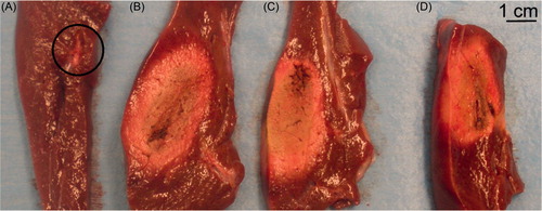
shows the four lesions created in each hepatic lobe in a representative case. In the first (A), in which EP only was performed, no coagulation ‘white area’ can be observed, but only a two 2-mm wide hyperaemia along the electrode path. In the second lobe, in which RFA alone was performed, a ‘white area’ of between 4.8 cm (maximum diameter) and 1.7 cm (minimum diameter) can be seen. In the third and fourth lobes (EP + RF procedure) a similar coagulation ‘white area’ between 4.2 cm (maximum diameter) and 1.6 cm (minimum diameter) were visible. No significant differences between EP and RF + EP groups were observed either in the maximum or in the minimum diameter ().
Figure 7. Lesions created in hepatic lobes after EP alone (A), RF ablation alone (B) and EP + RF ablation (C and D). In (A), the circle contains a two 2-mm wide hyperaemia along the electrode path, but no coagulation ‘white area’ was observed.
Discussion
This feasibility study was undertaken to assess whether the reduced blood perfusion caused by EP pulses applied prior to RFA would significantly reduce the thermal sink effect and hence increase coagulation volume to a greater extent than that created solely by RFA. We first conducted a computer modelling study, followed by a brief experimental study on an in vivo model.
Overall, the results suggest that no synergy effect can be achieved from this hybrid protocol, i.e. applying EP pulses prior to RFA does not increase the area of the coagulation zone. The additional computer simulations (Cases 3 and 4) could provide a possible explanation. In the case of RFA alone (Cases 2 and 4), the fact of not considering the effect of thermal damage on blood perfusion (case 4) is responsible for a reduction of 15% in the transverse diameter as compared to case 2, in which this factor was taken into consideration (2.94 cm versus 2.50 cm). This result agrees with other previous findings. However, when comparing the two EP + RFA cases (1 and 3), the transverse diameter decreased by only 4% when blood perfusion was not dependent on thermal damage (2.98 cm versus 2.84 cm), which suggests that the effect of EP is noticeable in case 3, i.e. only when the reduced blood perfusion due to thermal damage is not taken into account. In other words, the effect of reducing blood perfusion by thermal damage completely masks the effect of reducing blood perfusion by EP. This is due to the fact that both thermal damage and EP affect the tissue next to the electrode.
On one hand the disagreement between experimental and theoretical minor diameters both in cases EP + RF and RF could be due to the different criterion used to assess thermal damage. Since theoretical modelling used the Arrhenius damage model (with probabilities of cell death of 63% and 99%), it is possible that the computed boundaries do not match very well to the boundaries assessed macroscopically by the ‘white zone’. But especially, the values of the parameters A and ΔE used in the computation of Ω were obtained from previous experiments in which there is a broad variation; see for example Dos Santos et al. [Citation33]. Different values are provided depending on the experiment used. We checked that changes in the A value produced great differences in lesion dimensions. Then we chose A and ΔE values which provided reasonable results, i.e. lesion dimensions in an acceptable range (near a lethal isotherm (50–60 °C). However, due to the way in which A and ΔE are obtained and the great influence of A in the value of Ω, it was almost impossible to achieve a fine matching between computed and experimental lesions. In spite of this disagreement, the objective of the experiments was not to validate the theoretical model, but to confirm the results obtained from computer simulations.
The modelling study used a quasi-static approach, which works fine for electrosurgical frequencies (around 500 kHz). Probably over 2 MHz the displacement currents could take a role more and more important, and this approach could break down. However, in the range of RFA frequencies (300 kHz–1 MHz) these currents can be considered negligible.
Several limitations implicit in this study should be pointed out: (1) the theoretical model only considered the effect of EP on the reduction in blood perfusion, i.e. no late cytopathic effects (apoptosis) were modelled; and in relation to this, (2) the experimental model did not take into consideration the late effects since the coagulation zones were assessed immediately after the procedure. In spite of these limitations, we think that the effect of EP on reducing blood perfusion, at least with the monopolar arrangement tested here, is confined to the vicinity of the electrode, where the heating is mainly concentrated and the effect on blood perfusion is thus reduced. The impact of the EP pulses in terms of reducing blood perfusion is therefore masked by the subsequent RFA, which also has the effect of reducing blood flow.
On the other hand, one of the main limitations for thermal therapies is the heat sink effect caused by blood flow in major vessels, which may locally impede the thermal damage to the tumour, permitting neoplastic cell survival near these blood vessels. To date, the vascular effects from EP have not been shown to disrupt blood perfusion through these large vessels. For this reason, the conclusions of our study should be only considered in the case of combined EP + RFA therapy for tumours not adjacent to large vessels.
Conclusion
As far as we know, no previous studies have been conducted to check the possibility of combining RFA and EP to increase the size of the coagulation zones when ablating tumours. Our computer modelling and in vivo experimental findings suggest that this combination, when using monopolar applicators, does not provide an additional advantage as compared to the use of RFA alone.
Declaration of interest
This work received financial support from the Spanish ‘Plan Nacional de I + D + I del Ministerio de Ciencia e Innovación’ Grant nos. TEC2011-27133-C02-01,02 and TEC2010-17285, from the European Commission through the Marie Curie IRG grant TAMIVIVE (256376) and from the Universitat Politècnica de València (INNOVA11-01-5502; and PAID-06-11 Ref. 1988). The linguistic revision of this paper was funded by the Universitat Politècnica de València, Spain. The authors alone are responsible for the content and writing of the paper.
Related Research Data
References
- Poon RT, Fan ST, Tsang FH, Wong J. Locoregional therapies for hepatocellular carcinoma: A critical review from the surgeon's perspective. Ann Surg 2002;235:466–86
- Solbiati L, Livraghi T, Goldberg SN, Ierace T, Meloni F, Dellanoce M, et al. Percutaneous radio-frequency ablation of hepatic metastases from colorectal cancer: Long-term results in 117 patients. Radiology 2001;221:159–66
- Ahmed M, Brace CL, Lee FT Jr, Goldberg SN. Principles of and advances in percutaneous ablation. Radiology 2011;258:351–69
- Nikfarjam M, Muralidharan V, Christophi C. Mechanisms of focal heat destruction of liver tumors. J Surg Res 2005;127:208–23
- Burdio F, Mulier S, Navarro A, Figueras J, Berjano E, Poves I, et al. Influence of approach on outcome in radiofrequency ablation of liver tumors. Surg Oncol 2008;17:295–9
- Marty M, Sersa G, Garbay JR, Gehl J, Collins CG, Snoj M, et al. Electrochemotherapy – An easy, highly effective and safe treatment of cutaneous and subcutaneous metastases: Results of ESOPE (European Standard Operating Procedures of Electrochemotherapy) study. Eur J Cancer Supplements 2006;4:3–13
- Davalos RV, Mir IL, Rubinsky B. Tissue ablation with irreversible electroporation. Annals Biomed Eng 2005;33:223–31
- Sersa G, Cemazar M, Parkins CS, Chaplin DJ. Tumour blood flow changes induced by application of electric pulses. Eur J Cancer 1999;35:672–7
- Ramirez LH, Orlowski S, An D, Bindoula G, Dzodic R, Ardouin P, et al. Electrochemotherapy on liver tumours in rabbits. British J Cancer 1998;77:2104–11
- Bellard E, Markelc B, Pelofy S, Le Guerroué F, Sersa G, Teissié J, et al. Intravital microscopy at the single vessel level brings new insights of vascular modification mechanisms induced by electropermeabilization. J Control Release 2012;163:396–403
- Berjano EJ, Burdío F, Navarro AC, Burdío JM, Güemes A, Aldana O, et al. Improved perfusion system for bipolar radiofrequency ablation of liver. Physiol Meas 2006;27:55–66
- Pätz T, Körger T, Preusser T. Simulation of radiofrequency ablation including water evaporation. IFMBE Proc 2009;25:1287–90
- Trujillo M, Alba J, Berjano E. Relation between roll-off occurrence and spatial distribution of dehydrated tissue during RF ablation with cooled electrodes. Int J Hyperthermia 2012;28:62–8
- Duck F. Physical properties of tissue – A comprehensive reference book. New York: Academic Press, 1990
- Ivorra A, Rubinsky B. In vivo electrical impedance measurements during and after electroporation of rat liver. Bioelectrochemistry 2007;70:287–95
- Ivorra A, Mir LM, Rubinsky B. Electric field redistribution due to conductivity changes during tissue electroporation: experiments with a simple vegetal model. IFMBE Proc 2009;25:59–62
- Lacković I, Magjarević R, Miklavčič D. Incorporating electroporation-related conductivity changes into models for the calculation of the electric field distribution in tissue. XII Mediterranean Conference on Medical and Biological Engineering and Computing. IFMBE Proc 2010;29:695–8
- Sel D, Cukjati D, Batiuskaite D, Slivnik T, Mir LM, Miklavcic D. Sequential finite element model of tissue electropermeabilization. IEEE Trans Biomed Eng 2005;52:816–27
- Gehl J, Skovsgaard T, Mir LM. Vascular reactions to in vivo electroporation: Characterization and consequences for drug and gene delivery. Biochim Biophys Acta 2002;1569:51–8
- Pennes H. Analysis of tissue and arterial blood temperatures in the resting human forearm. J Appl Physiol 1948;85:5–34
- Pearce J, Panescu D, Thomsen S. Simulation of dioptre changes in radio frequency conductive keratoplasty in the cornea. WIT Trans Biomed Health 2005;8:469–77
- Yang D, Converse MC, Mahvi DM, Webster JG. Expanding the bioheat equation to include tissue internal water evaporation during heating. IEEE Trans Biomed Eng 2007;54:1382–8
- Byeongman J, Aksan A. Prediction of the extent of thermal damage in the cornea during conductive thermokeratoplasty. J Therm Biol 2010;35:167–74
- Abraham JP, Sparrow EM. A thermal-ablation bioheat model including liquid-to-vapor phase change, pressure- and necrosis-dependent perfusion, and moisture-dependent properties. Int J Heat Mass Tran 2007;50:2537–44
- Arata MA, Nisenbaum HL, Clark TW, Soulen MC. Percutaneous radiofrequency ablation of liver tumors with the LeVeen probe: Is roll-off predictive of response? J Vasc Interv Radiol 2001;12:455–8
- Berjano EJ. Theoretical modeling for radiofrequency ablation: State of-the-art and challenges for the future. Biomed Eng Online 2006;18;5:24
- Tungjitkusolmun S, Woo EJ, Cao H, Tsai JZ, Vorperian VR, Webster JG. Thermal-electrical finite element modeling for radio frequency cardiac ablation: Effects of changes in myocardial properties. Med Biol Eng Comput 2000;38:562–8
- Haemmerich D, Chachati L, Wright AS, Mahvi DM, Lee Jr FT, Webster JG. Hepatic radiofrequency ablation with internally cooled probes: Effect of coolant temperature on lesion size. IEEE Trans Biomed Eng 2003;50:493–500
- Chang IA, Nguyen UD. Thermal modeling of lesion growth with radiofrequency ablation devices. Biomed Eng Online 2004;3:27
- Chang IA. Considerations for thermal injury analysis for RF ablation devices. Biomed Eng Online 2010;4:3–12
- Jacques S, Rastegar S, Thomsen S, Motamedi M. The role of dynamic changes in blood perfusion and optical properties in laser coagulation of tissue. IEEE J Sel Top Quantum Electron 1996;2:922–33
- Goldberg SN, Grassi CJ, Cardella JF, Charboneau JW, Dodd GD III, Dupuy DE, et al. Society of Interventional Radiology Technology Assessment Committee; International Working Group on Image-Guided Tumor Ablation. Image-guided tumor ablation: Standardization of terminology and reporting criteria. J Vasc Interv Radiol 2009; 20:S377–S390
- Dos Santos I., Haemmerich D, Schutt D, Ferreira da Rocha A., Rax Menezes L. Probabilistic finite element analysis of radiofrequency liver ablation using the unscented transform. Phys Med Biol 2009;54:627–40