
Abstract
As the use of HIFU in the clinic becomes more widespread there is an ever increasing need to standardise quality assurance protocols, an important step in facilitating the wider acceptance of HIFU as a therapeutic modality. This article reviews pertinent aspects of HIFU treatment delivery, encompassing the closely related aspects of quality assurance and calibration. Particular attention is given to the description and characterisation of relevant acoustic field parameters and the measurement of acoustic power. Where appropriate, recommendations are made.
Introduction
High intensity focused ultrasound (HIFU) is being developed for use in the clinic, with the aim of enabling thermal ablation of tumours [Citation1–5], drug delivery [Citation6–8], and a number of other applications. As its use becomes more widespread, there is an ever increasing need to standardise the way in which the delivery of HIFU therapy is described and reported. The benefits of improved standardisation include a greater confidence in comparisons between studies across different sites using different equipment, easier regulatory approval and more consistent treatments. Appropriate standardisation addresses a number of aspects related to HIFU treatment and delivery. Firstly, a set of parameters relevant to the treatment mechanism need to be defined, and secondly, appropriate methods for measurement of such parameters must be devised, as must the measurement protocols to be followed. Closely related to standardisation is the field of quality assurance (QA), in which the aim is to ensure consistent and safe output from HIFU systems. It is important to measure parameters such as the peak focal pressure amplitudes and focal dimensions, to check the accurate positioning of the focus, to verify that hot spots are not inadvertently created in the beam, and to ensure that the transducer is not suffering from any kind of mechanical or electrical fault. The aim of this article is to review pertinent aspects relating to the quality assurance of HIFU devices. Relevant acoustic power and acoustic field mapping techniques are discussed, and where appropriate, recommendations are made.
HIFU transducers
HIFU transducers exist in a variety of shapes and sizes. The transducer geometry and drive frequency are largely dictated by clinical need, with the location, depth and accessibility of the target site all being important considerations. An important factor is the ability to deliver sufficient power at the required depth, in order to provide an effective treatment. These factors all influence transducer design. The focal length required is primarily determined by the depth of the target region and this, in turn, also affects the outer diameter of the transducer. For example, in order to reach deep-seated tumours in an adult, a long focal length (>∼15 cm) is required, and in order to achieve sufficient intensity in situ a large diameter (>20 cm) will also be necessary. The required penetration depth also has an impact on the ultrasound frequency [Citation9], as a balance must be struck between limiting attenuation losses in the overlying path (favouring a lower frequency), and achieving sufficient absorption at the focus (where a higher frequency is more desirable).
Large transducers can pose problems in terms of access to the treatment site. For example, in some situations, the available range of motion of the transducer in a confined space may be limited by its diameter, making it necessary to manipulate the position of the patient to gain optimal access to the target site. Another complicating factor is the coupling medium between the transducer and the patient. If the transducer is positioned above the patient a water bag is required. This can be cumbersome. A common solution for a number of ultrasound or MR guided systems is for the transducer to be positioned within a water bath incorporated into the bed, with the patient positioned on top [Citation10–11]. For ultrasound guided systems, an ultrasound imaging probe is often incorporated into the centre of the HIFU transducer, enabling imaging along the therapy beam axis [Citation12]. This arrangement means that a central portion of the HIFU transducer is removed to make space for the imaging probe.
A complete description of the transducer must therefore include all the geometrical properties (focal length, diameter, size of imaging aperture), and its frequency. More recently there has been a shift away from simple single element bowl transducers towards the use of phased array devices comprising a large number of independent transducer elements [Citation13–14]. Phased arrays offer the potential to control both phase and amplitude of each element, thus enabling focal steering and giving the ability to shape the ultrasound beam. The advantage of focal steering is that the position of the focus can be shifted rapidly and easily, without the need to physically move the transducer [Citation15–16]. This facilitates more complex treatment delivery regimes where the focus can be ‘swept’ over the course of a long exposure, thus ablating a much larger volume than would be possible using only single fixed location exposures.
Another advantage of phased arrays lies in the ability to control the drive amplitude of individual elements, meaning that the shape of the ultrasound beam can, to some extent, be manipulated to avoid exposing potentially sensitive structures in the beam path such as lung, bone, bowel and nerves [Citation14,Citation17–18]. The use of phased arrays thus further complicates the way in which HIFU treatments may be delivered, and with this, the way in which exposures should be described. In the case of phased arrays it is therefore important that quantities such as the number and size of elements be reported, and for electronically steered ablations some description of the focal trajectory (e.g. concentric circles) be given. Parameters which give some indication of the exposure conditions should be reported. The most basic description for clinical treatments usually involves reporting the electrical or acoustic power output of the transducer; however, generally speaking, this is not particularly useful or meaningful by itself. The reporting of localised acoustic field parameters such as pressure and intensity is preferable [Citation19]. A more detailed description of these parameters and how to measure them follows.
HIFU beam properties
A key feature of HIFU as a treatment modality is its ability to ablate tissue at depth inside the body without damaging tissue in the intervening path. This is achieved by bringing a considerable amount of acoustic power (>100 W) into a tight focus where the intensity can reach values potentially well in excess of 1000 W/cm2, while maintaining intensities in other regions at levels that do not cause tissue damage. At 0.8–2.0 MHz, the focal region is typically an ellipsoid, 1–3 mm wide and ∼10–30 mm long. In the focal plane, the power is not entirely contained within the focal region, with some power being in side-lobe rings around the focal region [Citation14,Citation20]. These are of lower intensity than the focus, and normally are of little consequence in clinical treatments for single exposures. However, their contributions can add up to become more significant for multiple exposures or steered beams. In the pre-focal beam the maximum intensity generally increases moving towards the focal plane; however, the intensity distribution is not smooth and presents localised regions of higher and lower intensity. It is thus important to know the intensity in the HIFU beam, particularly in any pre-focal regions of high intensity where skin burns can occur if repeated long exposures are to be used. This is true because of the much greater overlap of the intensity profiles in pre-focal planes over several exposures.
The situation is further complicated by the interaction of the HIFU beam with tissue as it propagates through the body. The primary mechanism for HIFU ablation is absorption of the ultrasound energy which results in an increase in temperature. Different tissues have different absorption coefficients, meaning that they heat at different rates. Some tissues or structures act as effective obstacles to the ultrasound beam. For example, bone is both more highly absorbing and more reflective than soft tissues, leading to increased heating in the superficial layers of the bone itself and in surrounding tissues, with the accompanying risk of thermal damage, and in some cases skin burns [Citation10,Citation21]. Bone is thus generally avoided during the planning of HIFU treatments of soft tissue targets, but deliberately targeted for the palliation of metastatic bone pain. Other structures to be avoided are those containing air, such as the lungs or bowel, as ultrasound will not propagate through these, and the beam will be reflected at any tissue/air interface, potentially giving rise to unwanted heating in adjacent organs or tissues.
Tissue may also affect the HIFU beam, changing its distribution from that measured in water. For example, de-focusing effects or shifts in focal position may occur due to the variations in sound speed in different tissues which may present non-planar layers. The situation can be further complicated by the fact that tissue properties (sound speed, absorption and attenuation) can also change as the tissue is heated [Citation22] by the ultrasound beam, and this may influence the effectiveness of the therapy. It is well known that sound speed increases in non-fatty tissue as the temperature is increased, up to a temperature of ∼50 °C, after which the sound speed decreases [Citation22]. Changes in tissue absorption lead to changes in the rate at which the ultrasound energy is absorbed and converted to heat, and significant changes in sound speed can influence the exact position of the focal peak (thermal lensing). In view of these facts, from a quality assurance point of view it is important that any changes in focal formation and positioning be detected. In a clinical setting this is best achieved using monitoring techniques. For ultrasound imaging, the presence of ‘bright-up’ (hyperechoic regions) has been used to indicate successful treatment [Citation2,Citation23–24]. An alternative is to use ultrasound thermometry [Citation25–26], although this may not be reliable in a quantitative sense [Citation27], and suffers from noise due to motion [Citation28]. In MR guided HIFU, proton resonance shift thermometry offers the ability to monitor temperature change in soft tissue with a good degree of accuracy (∼1 °C) [Citation29]; however, temporal resolution is limited to ∼1 frame per second using fast gradient recalled echo planar imaging sequences. It also suffers from motion artefacts, and the voxel size is often not much smaller than the HIFU focal volume.
Ultrasound field characterisation
The International Electrotechnical Commission (IEC) standards provide useful guidance on acoustic field characterisation. IEC 62555 [Citation30] and IEC 62556 [Citation31] give specific advice on HIFU power and acoustic field measurements respectively. IEC 61161 [Citation32] gives specific guidance on using acoustic radiation force balances for power measurements, and IEC 62127-1 [Citation33] gives advice on the use of hydrophones for acoustic field mapping. Further useful information may also be obtained in other published material [Citation34]. details the minimum set of parameters required for characterising a HIFU treatment, and methods for their measurement are outlined below.
Table 1. Parameters that should be measured for detailed description of HIFU fields.
Hydrophones
The most straightforward way to obtain quantitative absolute values of the acoustic field of a HIFU transducer is to use a hydrophone, a device which provides a localised measure of the acoustic pressure. Measurements are usually performed in water under so called ‘free-field’ conditions, in which the ultrasound beam propagates through a non-attenuating medium, in the absence of scattering structures. Ideally, the water should be degassed to avoid the formation of acoustic cavitation bubbles which can interfere with measurements, and also to minimise the risk of cavitation damage to the hydrophone [Citation35]. It may also be filtered and de-ionised, the latter being a requirement for measurements with co-planar membrane hydrophones where the conducting electrodes are exposed to the water. A number of components are required for the characterisation of HIFU acoustic fields. A water tank, a precise (<100 µm) positioning system, a hydrophone and a means of recording the hydrophone’s output signal are all basic requirements. It is desirable to be able to control the transducer output, preferably to allow pulsed or tone burst excitations in order to avoid standing waves and reflections. Another desirable feature is a motorised positioning system that allows a rapid series of measurements. This may be provided by the transducer’s own positioning system if present and sufficiently precise. An oscilloscope is often used to visualise, store and potentially process hydrophone signals. It is preferable to record entire waveforms.
There is a range of hydrophones available commercially that have been designed for the characterisation of both diagnostic and therapeutic ultrasound fields in the MHz range. Broadly, these can be divided into three categories: membrane, needles, and fibre-optic devices. The most commonly used membrane and needle hydrophones are based on polyvinylidene fluoride (PVdF), a piezoelectric polymer. Fibre-optic hydrophones operate by measuring changes in reflection from the tip of an optical fibre, which are due either to pressure-dependent changes in optical refractive index [Citation36], or through a Fabry-Perot interferometer design [Citation37–38]. Whilst all of these hydrophones may be used to characterise HIFU fields, it is worth considering the properties of each in order to establish which is likely to best fulfil the needs for a particular measurement. The choice of hydrophone is dependent on a number of factors, the main considerations being robustness, the measurement environment, sensor size, temporal stability, and flatness of the frequency response. Robustness is a critical factor in HIFU characterisation, since the hydrophone sensor is likely to be exposed to large peak negative pressures, and there is thus an associated risk of damage due to cavitation. The user therefore needs to have confidence in the hydrophone’s ability to withstand measurements without suffering damage, or change in the response characteristics of the device. In this respect membrane hydrophones are fairly robust and can measure acoustic pressures of several MPa, whereas probe-like sensors such as needles are more readily damaged by cavitation at the sensor tip [Citation39]. Some needle-like devices have been developed to be more robust. These include the HNA and HGL series hydrophones of the Onda Corporation (Sunnyvale, CA) [Citation35], and fibre-optic hydrophones which can measure very large pressure amplitudes (>10 MPa, RP-Acoustics, Leutenbach, Germany) [Citation36,Citation40]. Other factors such as noise levels, stability and frequency response are factors which may also need to be considered.
The measurement environment is another important factor. For example, the ease of access to the commercially available clinical HIFU transducers and the space available for measurements needs to be considered. With the emergence of MR guided HIFU systems there is also the need to consider MR compatibility of acoustic field characterisation equipment if the therapy transducer cannot be removed from the MR room. Hydrophone sensor size is an important consideration especially when there is a need to obtain accurate pressure measurements at the HIFU focal peak where the beam width can be sufficiently narrow (1 mm) that spatial averaging effects must be accounted for. It is always preferable to use a hydrophone with a sensor size small enough that spatial averaging errors are minimised. The general recommendation from relevant IEC standards [Citation31,Citation33] is that the effective sensor radius should be smaller than, or comparable to, a quarter of the acoustic wavelength. This requirement can be relaxed in the far field and an expression indicating the maximum effective sensor radius, am that may be used to limit spatial averaging errors is given here [Citation31,Citation33,Citation41]:
where λ is the wavelength, a is the transducer radius and l is the distance between the transducer and hydrophone position. This expression is given in the relevant IEC standard [Citation31]; however, it does not specify where in the field it should apply to. Another advantage of a small sensor is the lower variation in angular response, which can be useful if measurements are to be made in HIFU field positions away from the focal region where the relative angle between the hydrophone axis and the sound propagation direction is not aligned. For PVdF hydrophones the sensitivity typically increases with sensor size, and hence a compromise may be necessary when trying to balance the need for a strong signal-to-noise ratio and the requirement of a sufficiently small sensor. In general, the sensitivity of PVdF hydrophones is sufficient that for measurements around the HIFU focal region there is not usually the need for a large sensor in order to obtain sufficient signal to noise ratio, as the pressure amplitudes are large (>1 MPa). When characterising the pressure field far away from the focal region where much lower pressure amplitudes are likely, sensitivity becomes a more important consideration. One common solution to this problem is to employ signal averaging, in order to improve the signal to noise ratio. The frequency response is also important when choosing a hydrophone.
For HIFU field measurements a flat frequency response over the range 1–40 MHz is ideal, since this provides a voltage signal closely resembling the acoustic pressure signal. Membrane hydrophones typically offer the flattest frequency response and are therefore suited to the measurement of acoustic signals in HIFU fields which may contain a large number of harmonics. The hydrophone sensitivity at the drive frequency may be used to convert the measured voltage signal into acoustic pressure with minimal distortion due to the relative flatness of the hydrophone’s frequency response [Citation42]. The alternatives to membranes are needle or fibre-optic hydrophones which, due to their shape and construction, often have a less favourable frequency response which may include resonances and phase distortions [Citation38,Citation42,Citation43]. In these cases it becomes necessary to apply the hydrophone’s frequency dependent calibration data to deconvolve the measured voltage signal to obtain the underlying acoustic pressure waveform [Citation33]. This procedure can improve the reliability of measurement parameters provided an accurate characterisation of the magnitude and phase response of the hydrophone is available. Further considerations are likely to revolve around the physical shape of the hydrophone, the relative ease with which it can be mounted to perform the required measurements, and cost. Membrane hydrophones are usually mounted in a circular frame with a diameter of several centimetres; there may be occasions when hydrophones with these dimensions are unsuitable, such as when measurements are required close to bowl transducers, in which case a probe-like needle or fibre-optic hydrophone may be more practical.
Acoustic field characterisation should ideally be performed using a tone burst excitation. This is important for two reasons: firstly it eliminates problems associated with reflections and standing waves that may occur under constant wave sonication, and secondly it ensures that the duty cycle is lower, thus reducing the risk of damage to the transducer and hydrophone. In general only a low number of cycles are required per burst. The exact number will be determined by how rapidly the transducer can ramp up to a steady acoustic output level.
Another factor is the spatial extent of the scan. For example, if the hydrophone is to be used a considerable distance from the focal peak, the time of flight from all points on the transducer surface to the hydrophone needs to be taken into account. For most situations 40–50 cycles will probably easily suffice for measurements around the focal peak. For data processing, it is best to concentrate on a small number of cycles (<10) in the middle of the burst, where the pressure amplitude is stable. Conversion of the measured voltage signal to acoustic pressure requires a knowledge of the sensitivity, not only of the hydrophone, but also of any associated pre-amplifier. Where calibration data is provided by the manufacturer it is usually reported in units of mV/MPa, or similar, with some degree of uncertainty. The most straightforward conversion is to use the single value closest to the working frequency and simply divide the voltage by this sensitivity value. In some circumstances, where many harmonics are present, and where the hydrophone has a non-flat frequency response, a full deconvolution may be necessary. This can be achieved by obtaining the Fourier spectrum of the acquired voltage waveform using a Fast Fourier Transform (FFT); individual harmonic components can then be identified, their voltage amplitudes converted to pressure, and an inverse FFT can recover the acoustic waveform. This process enhances acoustic field characterisation. However, the amount of reduction in uncertainty in determining the peak positive and negative pressure amplitudes is not always easy to determine. The pressure parameters of interest are the peak positive and negative pressures, useful indicators for the potential of cavitation activity in a given tissue or medium, and the root-mean-square (RMS) pressure. The positive and negative pressure amplitude distributions often differ significantly in terms of peak location, magnitude and width. These effects occur because of the non-linear propagation and diffraction associated with the focused beam. The RMS pressure is a useful parameter in that, unlike the peak pressure parameters, it does not suffer from the same kind of distortions that affect the negative and positive pressure amplitudes, it is inherently less noisy, and can easily be used to estimate intensity. If transducer output efficiency is assumed to be comparable during continuous wave sonication and during low duty cycle tone burst exposures used during field measurement, the RMS pressure can then be used to determine the temporal average intensity (Ita)
where ρ is the mass density and c is the sound speed in water. The above expression is strictly valid only for plane waves where the pressure and velocity are in phase. In a focused field this condition is not generally true, although it is approximately valid at the focus and hence this expression is useful at the focal peak for most practical purposes, such as comparisons between different transducers for estimating rates of heating in tissues, for example. Further analysis of the pressure waveform can be carried out in terms of the spectral content. For instance, it is possible to quantify how the total intensity is distributed amongst the harmonics. This can be achieved by performing an FFT on the pressure waveform. In doing so it is important to ensure that the FFT window is an exact number of cycles. This is important for two reasons: first, it ensures that the FFT frequency bins are exactly centred on the harmonic frequencies, and secondly, it ensures that the power spectrum is correctly calculated with the intensity being distributed at the harmonics only, without frequency leakage effects. This type of analysis can be informative in comparing different devices, and to some extent may be useful in treatment planning. However it must be remembered that in a HIFU treatment, the effects of attenuation and the non-linear properties (B/A coefficient) of the tissue are likely to have a significant impact on the waveform shape, and the frequency content at the focus.
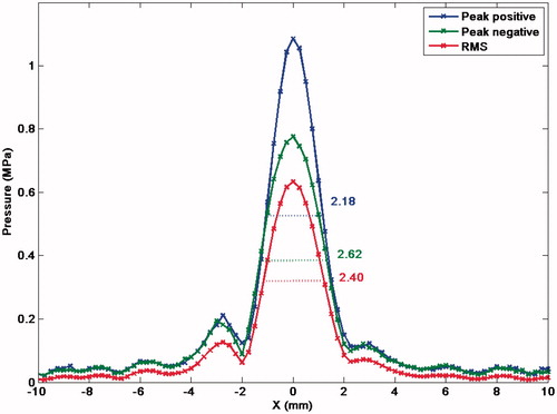
The most common hydrophone scans are likely to be linear and 2D planar scans. Linear scans centred at the focal peak can yield information about the focal size (−6 dB) in the axial and trans-axial directions. These are useful in quantifying focal dimensions, and give an indication of the extent of a typical single HIFU ablation (). It is important that these be measured in orthogonal axes in the trans-axial plane as radial symmetry cannot always be assumed, especially in the case of asymmetric transducers. Planar scans are more useful for visualising the HIFU beam shape, identifying any potential regions of high intensity outside the focus, and visualisation of any asymmetry. Examples of 2D planar scans are those in a trans-axial plane (at the focal plane, or at some other position in the beam), and those for which one axis is aligned with the sound axis. Scans in three dimensions are also a possibility; however, if sufficient resolution is required in three axes there is invariably a requirement for a very large number of measurement positions, which can often be prohibitive in terms of the time required to complete the scan. Furthermore, it is not good practice to leave hydrophones immersed in water for extended periods (>12 h).
Figure 1. Trans-axial beam plot of an 84-mm diameter spherical bowl transducer (15-cm focal length, 1.7-MHz driving frequency) at the focal plane, measured with an Onda HGL-0200 hydrophone. The peak positive, negative and RMS pressure profiles are indicated, together with their respective full width at half maximum (FWHM) measurements.
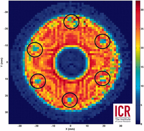
Recently there has been interest in using 2D planar scans in the pre-focal region to back-project the field at the transducer surface, in order to map out the pressure amplitude and phase at the transducer surface [Citation44]. This is potentially a useful quality assurance technique for phased arrays as it allows identification of malfunctioning elements which may not be easy to identify otherwise. It is also possible to use the result of the same 2D pre-focal scans to predict the pressure distribution at the focal plane using a non-linear forward projection [Citation31], thus allowing estimation of pressures at the focus which may be too high to be measured with a hydrophone. Another approach towards the same goal is to use a probe-like hydrophone to measure the acoustic pressure very close (a few mm) to the transducer surface over an appropriate curved spherical bowl grid (); however, this approach may not always be possible on clinical devices where it may not be possible to position the hydrophone sensor sufficiently close to the transducer.
Figure 2. RMS voltage amplitude (mV) for a curved spherical bowl transducer surface scan using a fibre-optic sensor close (<3 mm) to the surface of a 64-mm diameter, 63-mm focal length, 1.7-MHz HIFU transducer. The scan reveals solder connections (circled) arranged hexagonally which have reduced output.
Acoustic power measurement
The measurement of acoustic power provides a straightforward numerical description of a transducer’s output. Although on its own this quantity is not necessarily particularly meaningful, it becomes useful in a quality assurance and safety context. Monitoring acoustic power over long periods of time can highlight a reduction in transducer performance for example. From a safety point of view, abnormally high or low power outputs indicate some kind of system fault. Another advantage of measuring acoustic power is that, compared to field characterisation with a hydrophone, the measurement procedure is generally simpler and faster to perform. There are two approaches to measuring the ultrasonic power output: the first takes advantage of the radiation force phenomenon, and the second involves calorimetric techniques. The radiation force technique makes use of the fact that a propagating ultrasound wave carries momentum. If this momentum is absorbed or reflected, a net force will be applied on a target in the beam’s path [Citation30,Citation32,Citation45–48]. Calorimetric methods require the complete absorption of the energy carried by an ultrasound beam and its conversion to heat [Citation49–50], but these have traditionally been considered difficult, mainly due to the challenge of accurately measuring the extent of heating, but also in terms of limiting thermal losses. A recent development is the buoyancy approach [Citation51] which combines radiation force and calorimetry methods into one system.
Radiation force methods
Despite the fact that the radiation force generated by ultrasound is relatively weak (equivalent to 0.67 mN/W for an absorbing target), the radiation force method is the recognised primary standard for measuring acoustic power, it is possible to measure acoustic powers of the order of 1 mW using a precision balance [Citation52] under the right conditions. This technique is widely used to measure the output power of a large variety of ultrasound devices for both imaging and therapy, with many measurement systems being available commercially. An attractive feature of the radiation force technique is the relative simplicity with which the measured force can be converted to a power by multiplying with the sound speed. The only considerations to take into account are the type of target (absorbing or reflecting), its alignment with respect to the sound beam, and appropriate geometrical correction factors for the convergence of the beam or diffraction [Citation30]. One of the difficulties with reflecting targets is that the reflected beam must be directed away from the transducer so as not to set up standing waves and interfere with the measurement. Conical [Citation53] and angled reflecting [Citation54] targets have been reported in the literature; however, there is the potential for significant errors in using these kinds of targets with highly focused beams [Citation55]. An alternative to reflecting targets is the absorbing target [Citation56] in which, in principle, none of the incident ultrasound power is reflected, and hence there is much less concern over the alignment and geometry of the target material as long as the target is large enough to intercept the entire beam, and the HIFU axis is correctly aligned with the balance. The main problem with absorbing targets when measuring high power ultrasound beams, such as in HIFU, is the potential for significant heating in the target, which can lead to thermal expansion, changes in the target’s properties, or even material loss due to damage, all of which can lead to unstable results. A brush-type absorber has been proposed [Citation57] for use in HIFU beams, with promising results using pulsed exposures.
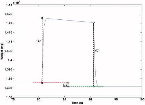
Another method has been proposed which consists of a large cylinder filled with castor oil acting as an ultrasound absorber [Citation30,Citation51,Citation58]. This neatly combines radiation force and calorimetry. The cylinder is immersed in a water tank and is supported from above by wire attached to a balance. The cylinder has a membrane at one end which acts as an acoustic window and is flexible. The HIFU beam is arranged to propagate through the flexible membrane, into the oil. Castor oil offers some attractive features as an absorbing material; it has a relatively low attenuation coefficient, meaning that the thermal energy is distributed over a larger volume, and, being a fluid, undergoes acoustic streaming which also facilitates redistribution of the absorbed energy. A second effect is expansion of the castor oil as it heats, resulting in a change in the buoyancy force acting on the target, which is also detected by the balance. The radiation force can therefore be used to estimate the acoustic power at each transition (off-on, on-off), while the change in measured weight due to buoyancy change is a cumulative effect depending on the total amount of energy absorbed during the ‘on’ period, and so this can be used to determine the average power output (). The buoyancy effect is small compared to the radiation force (∼0.35 mg/J sensitivity [Citation51]) but works well provided sonications are either powerful or lengthy enough to build up a significant signal (5 J being sufficient under good laboratory conditions) [Citation58]. The buoyancy method has the advantage that it requires no correction for the focused nature of a HIFU beam, and is independent of the alignment of the target and HIFU beam so long as the entirety of the beam area is absorbed by the castor oil. Thermal losses are a potential issue at frequencies above 3 MHz [Citation58], but provided the target is thermally large, and invariably this will be the case to accommodate the beam width of most HIFU transducers, the time scale over which heat is lost to the surrounding fluid is long compared to the duration of a measurement. The castor oil buoyancy system is therefore particularly well suited for power measurements up to several hundreds of Watts, thus offering an excellent tool for transducer quality assurance.
Figure 3. Example of acoustic power measurement (at 55 W) using a radiation force/buoyancy system showing the weight measured by a precision balance (Sartorius LA230S) for a 10-s sonication. The radiation force at onset (a), and offset (b) are indicated, together with the shift in baseline weight (c) due to the change in the buoyancy force.
Aside from routine QA purposes, acoustic power can potentially be used to infer spatial peak intensity. This can be done provided the acoustic field is characterised using a hydrophone to determine relevant pressure or intensity distributions, even if only at low power settings [Citation31]. The focal peak intensities may then be extrapolated for higher power settings. Hill et al. [Citation54] used this type of approach where power measurement data and hydrophone measurements of the focal −6-dB width, measured at low power, were used to derive estimates of the spatial peak intensity. This approach is particularly useful where the focal pressures or intensities cannot realistically be measured with a hydrophone; however, caution must be taken in this approach since it relies on a range of assumptions regarding the HIFU transducer and how the intensity is distributed in the beam.
Phantom and test devices
Acoustic field hydrophone and power output measurements provide invaluable information on the performance of a HIFU transducer, but fully comprehensive quality assurance requires a means of verifying the effectiveness of the entire HIFU system, including its targeting, guidance and monitoring capabilities. A means of monitoring the correct location of the focus and the temperature rise during treatment is of obvious importance in ascertaining therapeutic effects. It is in this area that phantom or test objects perform a vital role in quality assurance. HIFU test objects need to offer the ability to check for incorrect alignment of the HIFU treatment head with respect to the positioning and/or imaging system, and, ideally, some means of quantifying the intensity or temperature rise induced in a reference material. The nature of test objects is likely to depend on the imaging modality being used. For ultrasound guided systems, a phantom or test object which includes an embedded reflector or acoustic or thermal detector can be used. The principle is to localise, in turn, the HIFU and imaging beams on the target, to estimate any misalignment between the two axes. Hydrophones can be used for this purpose, as can an acoustic reflector (for example the end of a wire). For the latter a short HIFU burst consisting of a limited number of cycles would be required, and provided there is access to the transducer’s drive voltage channel the reflected echo can be detected with the transducer acting as a transmitter-receiver. An embedded thermocouple, which has the benefit of allowing temperature measurement may be used, or a Fabry-Perot fibre-optic hydrophone [Citation38] which can monitor both acoustic pressure and temperature change simultaneously. In an MR guided system a more suitable approach might be to use a purely thermal test phantom. Such an object would ideally be homogeneous and provide a strong MR signal with minimum artefacts, have tissue-like ultrasound properties (absorption, attenuation, sound speed, B/A parameter) and remain stable over time. The MRI system can be used to verify the location of the heating with respect to the targeted area, as well as providing a quantitative measure of the induced temperature rise.
While HIFU characterisation techniques that provide absolute values for parameters are essential for comparing both clinical and laboratory reported data, there is also a valuable role to be played by qualitative or semi-quantitative techniques, particularly for the visualisation of either acoustic or thermal profiles. A relatively simple but not widely used technique involves thermochromic dyes. These have been used as a film attached to a bone mimic in order to demonstrate the avoidance of rib heating when using a 10 strip-element transducer [Citation17]. The effect is reversible with time as long as damage to the film is avoided. More recently, a blue dye within a translucent phantom which loses its colour above a threshold temperature of 50 ° ± 3 °C has been reported [Citation59]. This allows visualisation of the size and position of the heated region. Similar results have been obtained in translucent polyacrylamide gels containing protein, either bovine serum albumin [Citation60] or egg-white [Citation61], where heat denaturation of the protein resulted in permanent opacity. Similar polyacrylamide gels mixed with corn syrup and doped with a non-ionic surface-active agent (NiSAA), polyoxyethylene alkyl ether series, provide a temperature-dependent clouding point [Citation62]. Although the clouding is mainly reversible, some hysteresis was noted. This formulation has the advantage that different clouding temperatures can be chosen, the range investigated being 66–80 °C.
Another method of thermal beam visualisation in which ultrasound is absorbed at a propagation medium/air interface at which a 0.2-mm thick acetate sheet is located has been developed. Infra-red (IR) imaging is used to quantify and visualise the heating distribution in sequential 2D slices with good spatial and thermal resolutions (0.044 mm and 0.05 °C) in order to construct a 3D image [Citation63], and has the advantage that it can cover wider temperature ranges and is independent of the start temperature. IR has been used to visualise the output of HIFU arrays [Citation64–65], and IR images have been compared to hydrophone scans [Citation66], showing good correspondence between the IR images and the intensity in focused and non-focused fields. A similar idea, but using an acoustically absorbing tile impregnated with thermochromic dye has also been developed for rapid visualisation of time-averaged intensity distributions, but has only been assessed at relatively low power for physiotherapy ultrasound equipment [Citation67–68]. Direct comparison of hydrophone beam plots with IR thermography in an absorbing phantom, and thermochromic film assessement of acoustically induced thermal profiles in a phantom by Gutierrez et al. [Citation69] showed the potential benefit and limitations of each technique as a qualitative or quantitative method. Another approach which allows visualisation of a HIFU beam is Schlieren imaging [Citation70–71], this takes advantage of changes in refractive index in the propagation medium which are induced by the acoustic pressure waveform. This technique is good for easily visualising the profile of a HFU beam; however, extracting quantitative information from these images is not straightforward. Other visualisation techniques include a holography approach [Citation44], and vibrometry methods [Citation72], which can give information about the oscillations at the transducer surface, or in the ultrasound beam [Citation73].
Conclusion
As the science and technology which underpins HIFU treatment continues to advance, there is an ever growing interest in developing appropriate methods to improve characterisation of the output of clinical HIFU devices and ensuring safe delivery of HIFU treatment. Of particular interest is calibration of HIFU transducers, where both acoustic power output measurement and acoustic field characterisation serve an important role in quality assurance and in enabling valid comparisons between studies across different sites and clinical systems around the world. Whilst there are significant challenges in characterising the output of clinical HIFU transducers due to the high powers, pressures, and intensities that are generated, progress has been made, and is ongoing, in developing systems able to measure these parameters. Relevant IEC standards [Citation30–33] provide a good starting point, as they describe in detail the appropriate methods for measuring the power output of HIFU transducers and the characterisation of acoustic fields. Furthermore, when quantitative studies aimed at establishing correlation between HIFU exposure and a therapeutic effect are to be performed, the recommendation is that the method of how to measure and quantify the ultrasound exposure must be carefully considered before the study has begun, and certainly long before the study is written up [Citation74]. In addition to this, the aim must always be to measure and report the relevant parameters (pressure amplitudes, intensity, acoustic frequency, acoustic power, duty cycles, beam width, for example) used in the study [Citation19]. Measurements performed under free-field conditions are acceptable. Where de-rating factors are used to determine in situ values, these must be fully explained. It is hoped that if the wider HIFU community takes up these recommendations it will naturally bring about a more rigorous approach to reporting of exposure conditions. Furthermore, as measurement techniques and their use become standardised it will encourage regular quality assurance on clinical systems. This will ultimately lead towards widely accepted safety and quality assurance protocols which will give further credence to HIFU as a therapeutic modality in the clinic.
Declaration of interest
The authors report no conflicts of interest. The authors alone are responsible for the content and writing of the paper.
References
- ter Haar GR, Coussios CC. High intensity focused ultrasound: Past, present and future. Int J Hyperthermia 2007;23:85–7
- Illing RO, Kennedy JE, Wu F, ter Haar GR, Protheroe AS, Friend J, et al. The safety and feasibility of extracorporeal high-intensity focused ultrasound (HIFU) for the treatment of liver and kidney tumours in a western population. Br J Cancer 2005;93:890–5
- Crouzet S, Murat FJ, Pasticier G, Cassier P, Chapelon JY, Gelet A. High intensity focused ultrasound (HIFU) for prostate cancer: Current clinical status, outcomes and future perspectives. Int J Hyperthermia 2010;26:796–803
- Dubinsky TJ, Cuevas C, Dighe MK, Kolokythas O, Hwang JH. High-intensity focused ultrasound: Current potential and oncologic applications. Am J Roentgenology 2008;190:191–9
- Xiong LL, Hwang JH, Huang XB, Yao SS, He CJ, Ge XH, et al. Early clinical experience using high intensity focused ultrasound for palliation of inoperable pancreatic cancer. J Pancreas 2009;10:123–9
- Frenkel V. Ultrasound mediated delivery of drugs and genes to solid tumours. Adv Drug Del Rev 2008;60:1193–208
- Ranjan A, Jacobs GC, Woods DL, Nwgussie AH, Partanen A, Yarmolenko PS, et al. Image-guided drug delivery with magnetic resonance guided high intensity focused ultrasound and temperature sensitive liposomes in a rabbit Vx2 tumor model. J Control Release 2012;158:487–94
- De Smet M, Heljman E, Langereis S, Hijnen NM, Grull H. Magnetic resonance imaging of high intensity focused ultrasound mediated drug delivery from temperature-sensitive liposomes: An in-vivo proof-of-concept study. J Control Release 2011;150:102–10
- Hill CR. Optimum acoustic frequency for focused ultrasound surgery. Ultrasound Med Biol 1994;20:271–7
- Kennedy JE, Wu F, ter Haar GR, Gleeson FV, Phillips RR, Middleton MR, et al. High-intensity focused ultrasound for the treatment of liver tumours. Ultrasonics 2004;42:931–5
- Voogt MJ, Trillaud H, Kim YS, Mali WPTM, Barkhausen J, Bartels LW, et al. Volumetric feedback ablation of uterine fibroids using magnetic resonance-guided high intensity focused ultrasound therapy. Eur Radiol 2012;22:411–17
- Wu F, Wang ZB, Chen WZ, Zhu H, Bai J, Zou JZ, et al. Extracorporeal high intensity focused ultrasound ablation in the treatment of patients with large hepatocellular carcinoma. Ann Surg Oncol 2004;11:1061–9
- Daum DR, Hynynen K. A 256-element ultrasonic phased array system for the treatment of large volumes of deep seated tissue. IEEE Trans Ultrason Ferroelectr Freq Contol 1999;46:1254–68
- Bobkova S, Gavrilov L, Khokhlova V, Shaw A, Hand J. Focusing of high-intensity ultrasound through the rib cage using a therapeutic random phased array. Ultrason Med Biol 2010;36:888–906
- Pernot M, Aubry JF, Tanter M, Thomas JL, Fink M. High power transcranial beam steering for ultrasonic brain therapy. Phys Med Biol 2003;48:2577–89
- Auboiroux V, Dumont E, Petrusca L, Viallon M, Salomir R. An MR-compliant phased-array HIFU transducer with augmented steering range, dedicated to abdominal thermotherapy. Phys Med Biol 2011;56:3563–82
- Civale J, Clarke R, Rivens I, ter Haar GR. The use of a segmented transducer for rib sparing in HIFU treatments. Ultrasound Med Biol 2006;32:1753–61
- Aubry JF, Pernot M, Marquet F, Tanter M, Fink M. Transcostal high-intensity-focused ultrasound: Ex vivo adaptive focusing feasibility study. Phys Med Biol 2008;53:2937–51
- ter Haar GR, Shaw A, Pye S, Ward B, Bottomley F, Nolan R, Coady A. Guidance on reporting ultrasound exposure conditions for bio-effects studies. Ultrasound Med Biol 2011;37:177–83
- O’Neil HT. Theory of focusing radiators. J Acoust Soc Am 1949;21:516–26
- Li JJ, Gu MF, Luo GY, Liu LZ, Zhang R, Xu GL. Complications of high intensity focused ultrasound for patients with hepatocellular carcinoma. Technol Cancer Res Treatment 2009;8:217–24
- Bamber JC, Hill CR. Ultrasonic attenuation and propagation speed in mammalian tissues as a function of temperature. Ultrasound Med Biol 1979;5:149–57
- Vaezy S, Shi X, Martin RW, Chi E, Nelson PI, Bailey MR, et al. Real-time visualization of high-intensity focused ultrasound treatment using ultrasound imaging. Ultrasound Med Biol 2001;27:33–42
- Rabkin B, Zderic V, Vaezy S. Hyperecho in ultrasound images of HIFU therapy: Involvement of cavitation. Ultrasound Med Biol 2005;31:947–56
- Liu D, Ebbini ES. Real-time 2-D temperature imaging using ultrasound. IEEE Biomed Engineering 2010;57:12–16
- Seip R, Ebbini ES. Noninvasive estimation of tissue temperature response to heating fields using diagnostic ultrasound. IEEE Biomed Engineering 1995;42:828–39
- Civale J, Rivens I, ter Haar G, Morris H, Coussios C, Friend P, et al. Calibration of ultrasound backscatter temperature imaging for high-intensity focused ultrasound treatment planning. Ultrasound Med Biol 2013;39:1596–612
- Kolen AF, Miller NR, Ahmed EE, Bamber JC. Characterization of cardiovascular liver motion for the eventual application of elasticity imaging to the liver in vivo. Phys Med Biol 2004;49:4187–206
- Ishihara Y, Calderon A, Watanabe H, Okamoto K, Suzuki Y, Kuroda K, Suzuki Y. A precise and fast temperaturemapping using water proton chemical shift. Magn Reson Med 1995;34:814–23
- IEC 62555 ed1.0: Ultrasonics – Power measurement – High intensity therapeutic ultrasound (HITU) transducers and systems. Geneva: International Electrotechnical Commission 2014
- IEC/TS 62556, ed1.0: Ultrasonics – Surgical systems – Specification and measurement of field parameters for High Intensity Therapeutic Ultrasound (HITU) transducers and systems. Geneva: International Electrotechnical Commission 2014
- IEC 61161, ed3.0: Ultrasonics – Power measurement – Radiation force balances and performance requirements. Geneva: International Electrotechnical Commission 2013
- IEC 62127-1 ed1.0: Ultrasonics – Hydrophones – Part 1: Measurement and characterization of medical ultrasonic fields up to 40 MHz. Geneva: International Electrotechnical Commission 2007
- Preston RC. Output Measurement for Medical Ultrasound. London: Springer-Verlag, 1991
- Zanelli CI, Howard SM. A robust hydrophone for HIFU metrology. Am Inst Phys 5th Int Symp Therapeut Ultrasound, 2006;829:618–22
- Staudenraus J, Eisenmenger W. Fibre-optic probe hydrophone for ultrasonic and shock-wave measurements in water. Ultrasonics 1993;31:267–73
- Beard PC, Mills TN. Extrinsic optical-fiber ultrasound sensor using a thin polymer film as a low-finesse Fabry-Perot interferometer. Applied Optics 1996;35:663–75
- Morris P, Hurrell A, Shaw A, Zhang E, Bear P. A Fabry-Perot fiber-optic ultrasonic hydrophone for the simultaneous measurement of temperature and acoustic pressure. J Acoust Soc Am 2009;125:3611–22
- Haller J, Jenderka KV, Durando G, Shaw A. A comparative evaluation of three hydrophones and a numerical model in high intensity focused ultrasound fields. J Acoust Soc Am 2012;131:1121–30
- Canney MS, Khokhlova VA, Bessonova OV, Bailey MR, Crum LA. Shock-induced heating and millisecond boiling in gels and tissue due to high intensity focused ultrasound. Ultrasound Med Biol 2010;36:250–67
- Beissner K. Maximum hydrophone size in ultrasound field measurements. Acustica 1985;59:61–6
- Wear KA, Gammell PM, Maruvada S, Liu Y, Harris GR. Improved measurement of acoustic output using complex deconvolution of hydrophone sensitivity. IEEE Trans Ultrason Ferroelectr Freq Control 2014;61:62–75
- Haller J, Wilkens V, Jenderka K, Koch C. Characterization of a fiber-optic displacement sensor for measurements in high-intensity focused ultrasound fields. J Acoust Soc Am 2011;129:3676–81
- Kreider W, Yuldashev PV, Sapozhnikov OA, Farr N, Partanen A, Bailey MR, et al. Characterization of a multi-element clinical HIF?U system using acoustic holography and nonlinear modelling. IEEE Trans Ultrason Ferroelectr Freq Control 2013;60:1683–98
- Torr GR. The acoustic radiation force. Am J Phys 1984;52:402–8
- Davidson F. Ultrasonic power balances. In: Preston RC, ed. Output measurements for medical ultrasound. London: Springer Verlag, 1991, pp. 75–89
- Brendel K. Molkenstruck W. Reibold R. Targets for ultrasonic power measurements. In: Proc 3rd Eur Congress on Ultrasonics in Medicine, Edizioni Centro Minerva Medica, Bologna 1978, p. 473
- Beissner, K. Minimum target size in radiation force measurements. J Acoust Soc Am 1984;76:1505–10
- Herman BA, Stewart HF. An ultrasonic radiation calorimeter. J Acoust Soc Am 1973;53:341
- Delchar TA, Melvin RJ. A calorimeter for ultrasound total power measurements. Meas Sci Technology 1994;5:1533–7
- Shaw A. A buoyancy method for the measurement of total ultrasound power generated by HIFU transducers. Ultrasound Med Biol 2008;34:1327–42
- Hekkenberg RT, Beissner K, Zeqiri B, Bezemer RA, Hodnett M. Validated ultrasonic power measurements up to 20 W. Ultrasound Med Biol 2001;27:427–38
- Shotton KC. A tethered float radiometer for measuring the output from therapy equipment. Ultrasound Med Biol 1980;6:131–3
- Hill CR, Rivens I, Vaughan MG, ter Haar GR. Lesion development in focused ultrasound surgery: A general model. Ultrasound Med Biol 1994;20:259–69
- Shaw A, Hodnett M. Measurement and calibration issues for therapeutic ultrasound. Ultrasonics 2008;48:234–52
- Sutton Y, Shaw A, Zeqiri B. Measurement of ultrasonic power using an acoustically absorbing well. Ultrasound Med Biol 2003;29:1507–13
- Maruvada S, Harris GR, Herman BA, King RL. Acoustic power calibration of high-intensity focused ultrasound transducers using a radiation force technique. J Acoust Soc Am 2007;121:1431–9
- Rajagopal S, Shaw A. Buoyancy method – A potential new primary ultrasound power standard. Metrologia 2012;49:327–39
- Dabbagh A, Abdullah BJ, Abu Kasim NH, Ramasindarum C. Reusable heat-sensitive phantom for precise estimation of thermal profile in hyperthermia application. Int J Hyperthermia 2014;30:66–74
- Lafon C, Zderic V, Noble ML, Yuen JC, Kaczkowski PJ, Sapozhnikov OA, et al. Gel phantom for use in high-intensity focused ultrasound dosimetry. Ultrasound Med Biol 2005;31:1383–9
- Divkovic GW, Liebler M, Braun K, Dreyer T, Huber PE, Jenne JW. Thermal properties and changes of acoustic parameters in an egg white phantom during heating and coagulation by high intensity focused ultrasound. Ultrasound Med Biol 2007;33:981–6
- Park SK, Guntur SR, Lee KI, Paeng DG, Choi MJ. Reusable ultrasonic tissue mimicking hydrogels containing nonionic surface-active agents for visualizing thermal lesions. IEEE Trans Biomed Eng 2010;57:194–202
- Shaw A, Nunn J. The feasibility of an infrared system for real-time visualization and mapping of ultrasound fields. Phys Med Biol 2010;55:N321
- Hand JW, Shaw A, Sadhoo N, Rajagopal S, Dickinson RJ, Gavrilov LR. A random phased array device for delivery of high intensity focused ultrasound. Phys Med Bio 2009;54:5675–93
- Bobkova S, Gavrilov LR, Khokhlova V, Shaw A, Hand J. Focusing of high-intensity ultrasound through the rib cage using a therapeutic random phased array. Ultrasound Med Biol 2010;36:888–906
- Khokhlova V, Shmeleeva S, Gavrilov L, Gelat PN, Martin EM, Shaw A. Infrared mapping of ultrasound fields generated by medical transducers: Feasibility of determining absolute intensity levels. J Acoust Soc Am 2013;134:1586–97
- Martin K, Fernandez R. A thermal beam-shape phantom for ultrasound physiotherapy transducers. Ultrasound Med Biol 1997;23:1267–74
- Butterworth I1, Barrie J, Zeqiri B, Žauhar G, Parisot B. Exploiting thermochromic materials for the rapid quality assurance of physiotherapy ultrasound treatment heads. Ultrasound Med Biol 2012;38:767–76
- Gutierrez MI, Leija L, Vera A. Therapy ultrasound equipment characterization: Comparison of three techniques. Conf Proc IEEE Eng Med Biol Soc 2008;5117–20
- Christensen DA, Chao A. A pulsed Schlieren system for visualizing beams from phased-array HIFU applicators. In: AIP Conf Proc 6th Int Symp Therapeut Ultrasound 2007;911:15–19
- Kudo N, Ouchi H, Yamamoto K, Sekimizu H. A simple Schlieren system for visualizing a sound field of pulsed ultrasound. J Phys Conf Ser 2004;1:146–9
- Song J, Hynynen K. Feasibility of using lateral mode coupling method for a large scale ultrasound phased array for noninvasive transcranial therapy. IEEE Trans Biomed Eng 2010;57:124–33
- Wang Y, Tyrer J, Zhihong P, Shiquan W. Measurement of focused ultrasonic fields using a scanning laser vibrometer. J Acoust Soc Am 2007;121:2621–7
- Shaw A, ter Haar GR. Telling it like it is. J Therapeutic Ultrasound 2013;1:4