
 ?Mathematical formulae have been encoded as MathML and are displayed in this HTML version using MathJax in order to improve their display. Uncheck the box to turn MathJax off. This feature requires Javascript. Click on a formula to zoom.
Abstract
The main challenge in transcostal high-intensity focused ultrasound therapy is minimising heat deposition in the ribs while ensuring that a sufficient dose is delivered to the target region. Current approaches rely on expensive multichannel phased-array systems to turn the individual transducer on and off according to either geometrical arrangements or complicated wave calculations. To protect the ribs from heating, the ultrasound energy must not only not reach the ribs, but must also not accumulate in front of the ribs. The research in this paper proposes a different approach, of attaching a sound-blocking structure in front of the rib cage with similar effects to those of an engine exhaust muffler. The sound-blocking structure is based on the muffler principle to prevent ultrasound energy from reaching the ribs and reduce the amount of energy reflected back to the applicator. Finite element simulations with a 0.5-MHz transducer of the overall sound fields and temperature distribution showed that the ultrasound pressure and energy level would decrease behind the novel sound-blocking structures, thereby resulting in a lower temperature at the ribs than at the tumour. Without the protecting structure, the rib temperature reached 104.19 °C whereas with the structure it reached only 37.86 °C. An experimental set-up using porcine ribs with a phantom was also developed to validate the concept, which showed that the rib temperature reached 73 °C without protection within 1 min of ablation time whereas it reached 36.5 °C with the device. The tumour region in the tests reached 51 °C and 49 °C with and without protection, respectively.
Introduction
Over the years, high intensity focused ultrasound (HIFU) has become an effective method for cancer treatment [Citation1–4], as evidenced by reports describing the effective treatment of prostate cancer [Citation5], breast cancer [Citation6], kidney cancer [Citation7], liver cancer [Citation8,Citation4], brain tumours [Citation9], and pancreatic cancer [Citation10] using this therapy. More recent studies have turned their attention towards using HIFU to treat harder-to-reach tumours, resulting in the development of transcostal HIFU.
Bones in the HIFU wave propagation passage exhibit different characteristics from those of tissue, and thus undesirable diffraction and absorption occur [Citation11]. In the case of transcostal HIFU, the rib cage not only accumulates heat, resulting in patient discomfort, but also acts as an aberrator to the focusing beam [Citation12–14]. Bobkova et al. [Citation15] compared rib-sparing HIFU approaches to ‘geometric’ and ‘diffraction’ approaches. The earlier ‘geometric’ approaches switch off the transducers that are ‘geometrically’ obstructed by the ribs [Citation16–19]. To account for the scattering, ‘diffraction’ approaches make use of the wave characteristics to further enhance focusing. Aubry et al. proposed time-reversal focusing to control the firing of ultrasound pulses so that they build up at the tumour site and cause ablation [Citation20,Citation21]. Bobkova et al. took into account the diffraction effects and used a phase conjugation method to improve focusing and provide better protection of the ribs [Citation15]. Simulation of transcostal HIFU involves the solution of the Rayleigh–Sommerfeld integral [Citation17]. Gelat et al. proposed the use of the boundary element approach, which is based on a generalised minimal residual implementation of the Burton–Miller formulation, to address the scattering and diffraction effects [Citation22]. The same authors later reformulated the constraint optimisation problem to enhance the pressure focusing effects [Citation23]. The temperature effects of HIFU are being addressed using results based upon the Pennes equation [Citation24–26]. A model including the dynamic changes that occur in the physical properties of tissues as a result of heating during feedback-controlled thermal ablation has also been reported [Citation27]. Marquet et al. [Citation28] developed a sequence combining real-time three-dimensional (3D) transcostal movement correction and the spiral trajectory of the HIFU beam. Some recent studies also investigated the use of magnetic resonance imaging (MRI) to assist with both positioning and lesion detection [Citation9,Citation29].
An immediate solution to the rib-heating problem would be the positioning of energy absorbing strips in front of the ribs to block the path of the ultrasound waves. However, this approach is not feasible; we found that the temperature required for ablation of the tumour could not be reached using this method because the blocking strips accumulated too much energy and raised the temperature of the strips to an uncomfortable level near the skin. If the concept of using energy absorption is invalid, the energy dissipation concept may provide an alternative. By energy dissipation we mean the use of devices that direct the energy elsewhere. The exhaust muffler used in vehicles suppresses the engine sound by either dissipating it through the muffler chamber or reflecting it back into the cylinders. However, applying the muffler concept to the human body raises a number of concerns, such as the large size, which would prevent the positioning of the muffler in front of the rib cage. Fortunately, ultrasound wavelengths and frequencies allow the design of smaller muffling structures that fit the rib cage better. The muffler concept is thus a realistic approach, and theoretical guidelines for the design are available [Citation30,Citation31]. It is important to note that the sound energy does not disappear; a portion of the undissipated energy is reflected back to the applicator [Citation32] and could potentially damage the transducer. Thus, care must be exercised in the design to minimise this reflected energy. It is also important to note that a HIFU ultrasound blocking device differs in a number of ways from an exhaust muffler. Whereas the interfacing medium of the exhaust muffler is air, which has a low density and small temperature change during sound propagation, the interfacing medium of the ultrasound blocking design is water, which has a high density, and consequently large amounts of energy exchange and large temperature changes will occur. The fact that the medium is water acts in favour of the design of a HIFU ultrasound blocking device because convection would carry away most of the heat dissipated by the device. The impedance design of the acoustic channel is also important to minimise energy reflection.
This paper presents the procedures involved in the design of a multi-section ultrasound suppression device. Various muffling structures were explored to determine an effective combination. The goal for the design was to achieve ultrasound ablation behind the ribs and to prevent the ribs from overheating. Numerical simulations were used to demonstrate design performance. The simulations included all the elements required, including the transducer characteristics, the ultrasound phenomena, and water, the transmission medium [Citation31–35]. It was observed that channel volume and medium density affected the ratio of energy penetration to energy loss. The simulations included both the ultrasound intensity and the bioheat transfer equation for temperature distribution. The results showed that it was possible to design resonance chambers that dissipate sound energy travelling through the channel. The dissipated heat was carried away by water convection. Different designs also had different impedance distributions across the sound field. Changes in sound path impedance reduced the amount of sound energy reflected back to the transducer. Two designs are presented: an innovative resonator-based design and a conventional expansion muffler-based design. The structures presented herein could be attached directly in front of the rib cage and would therefore be very easily applicable in the clinic.
Theoretical background
The HIFU system represents a highly sophisticated integration of modern technologies involving a piezoelectric transducer, acoustic focusing and interference, and bioheat transfer. The proposed muffling structure requires detailed knowledge of acoustic design. This section provides a brief description of the related theoretical background. Specifically, the second section will describe the design principles for two muffler design approaches based on the expansion muffler principle and the resonator principle. The actual design will then be presented in the third section.
Sound field theory
Following previous assumptions [Citation22], this paper does not address the non-linear problem of HIFU wave propagation, and restricts considerations to the propagation of harmonic acoustic waves passing through a homogeneous isotropic medium. The three basic equations governing the acoustic disturbances of an ideal fluid are the conservation equations and the physical equation of state. The conservation equations include the equations of motion that govern the momentum conservation, the continuity equation for mass conservation, and the energy conservation equation. The physical equation of state is represented by the entropy equation. The relationships between these equations are non-linear. If the acoustic parameters are assumed to change only slightly with location and over time, the higher order terms can be assumed to be negligible. The wave propagation equation is thus:
(1)
(1)
where P is the acoustic pressure, and ρc and cc are frequency dependent variables obtained by
(2)
(2)
and
(3)
(3)
where kc in Equation Equation3
(3)
(3) is the complex wave number and Zc denotes the complex impedance, which in turn are described by
(4)
(4)
and
(5)
(5)
where α is the attenuation coefficient.
The surface vibration of the transducer induces ultrasonic energy emission; thus normal acceleration on the surface constitutes the boundary condition for the incident beam.
It is possible to define the vibration of the probe using the inward normal acceleration, an, at the boundary as in Equation Equation6(6)
(6)
(6)
(6)
where an in can be viewed as a sound source term.
With these basic principles in hand, a simulation based on these acoustic equations can be performed to analyse sound intensity and thus ultrasound ablation along the pathway.
Expansion muffler principle
The muffler is often designed to dissipate sound energy. In , sound waves are depicted travelling through a tube with a cross-sectional area S1 and entering another tube with a cross-sectional area S2. The length of the expansion chamber is D.
Figure 1. Expansion muffler structure.
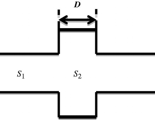
The different cross-sectional areas of the two tubes mean that the second tube constitutes a load that induces sound reflection and transmission. Assuming the region of non-uniformity is much smaller than the ultrasound wave length, the ratio of the sound pressures of the transmitted wave at x = D and the incident wave at x = 0 (after some algebraic operations) will be as in Equation Equation7(7)
(7) [Citation32,Citation36]
(7)
(7)
where S12 = S2/S1, S21 = S1/S2.
The ratio of the intensities of the transmitted and incident waves is called the sound intensity transmission coefficient, which can be expressed as Equation Equation8(8)
(8) .
(8)
(8)
This formula indicates that the transmission of sound through tubes with different cross sections is influenced by the ratios of both their cross-sectional areas and lengths [Citation36]. When kD = (2 n − 1)(π/2), which means D = (2 n − 1)(λ/4), n = 1, 2,…, the minimum transmission coefficient can be expressed as 4S12/(1 + S12)2. This corresponds to a situation where the length of the tubes is one-quarter the wavelength of the incident sound, for which sound transmission is minimum, corresponding to the filtering of specific frequencies.
Note that the formulae are based on two-dimensional analysis. This is because the desired sound-blocking structure is a strip that is placed in front of the ribs. Thus, a two-dimensional design is a reasonable approach. Also, the dimensions of the chambers have to be about the right size for positioning in front of the ribs. Fortunately, an ultrasound wavelength of a few millimetres approximates the right dimension for the rib-sparing structure.
Resonator principle
The previous subsection described the necessary tube dimensions required to reduce energy transmission; however, the reduction is achieved by reflecting the energy back to the source. In this section we show a different approach that blocks ultrasound transmission by dissipating it within a resonance chamber. Using this approach, the impedance of the sound path can be changed and energy efficiency can be improved.
Consider a Helmholtz resonator attached to one side of a tube, as shown in . If the resistance to sound propagation is neglected, the reactance to sound propagation can be expressed as in Equation Equation9(9)
(9) .
(9)
(9)
Figure 2. Side resonance structure.

The acoustic mass of the cavity is
(10)
(10)
where l and Sb are the length and cross-section of the (short) resonator tube. The acoustic compliance of the cavity is
(11)
(11)
where Vb is the cavity volume. Based on the continuity conditions for sound pressure and volume velocity, transmission coefficient is then expressed as
(12)
(12)
indicating that when
, the side resonator exhibits a high filtration efficiency.
This theorem basically provides a way to change the impedance of the sound-blocking structure. Changing the impedance of the resonator channel causes a change in total impedance, and thus the amount of energy transmitted. Given a limited frequency range for the incident source such as 0.5 MHz, it is possible to choose the appropriate length and thickness of the edges of the resonance structure. The acoustic resonance phenomenon will then lead to high filtration efficiency.
Bioheat transfer theory
The effect of the ultrasound beam on biomass also needs consideration. The time variation and the temperature distribution of the heating effect are based on the Pennes equation [Citation37]. The Pennes equation (as in Equation Equation13(13)
(13) ) takes into account blood perfusion, metabolism, and the heat conduction of the tissue.
(13)
(13)
where T is the temperature of the tissue; ρt and ct are the density and the specific heat of the tissue, respectively; kt is the thermal conductivity of biological tissue; wb is the blood perfusion rate; cb is the specific heat of blood; Tb is the temperature of the blood vessel; Qma is the heat generated by metabolism; Qr is the external heat source;
is the heat absorption of the tissue;
is the heat conduction of the tissue; and
is the thermal convection term in the Pennes equation that addresses perfusion in the blood vessel. Heat is brought into or out of the vessel by convection to regulate tissue temperature. Qm is the heat generated by human metabolism and is approximately 420
[Citation38]. The last term is the external heat source, Qr. In this case, the heat source arises from the attenuation of acoustic energy [Citation39]:
(14)
(14)
where p* is the complex conjugate number and α is the acoustic absorption coefficient; I in (3.2) is the magnitude of acoustic intensity; p is the acoustic pressure; and νp is the vector of acoustic particle velocity.
Another heat source is created in the HIFU ablation space when the fluid medium experiences strong friction with the surface of the structure within which the acoustic wave resonates. This phenomenon is termed ‘viscous dissipation’. Acoustic energy dissipated by friction Qf can be expressed as below [Citation40]
(15)
(15)
where μ is the viscosity and v is the flow velocity vector. The resultant temperature in human tissue that arises from the heat source acoustic attenuation and metabolism is then computed using the Pennes equation. The heat source in the propagation medium, on the other hand, arises from acoustic attenuation and viscous dissipation.
The structure design
The expansion chamber design
The first structure is based on the expansion muffler principle and is designed for use at 0.5 MHz, which is assumed to be the excitation frequency. shows the relationship between the transmission coefficient of the channel and the length of the expansion chamber. The figure indicates that the reflectivity of the sound-blocking structure will be highest when D = 2.25 mm and lowest when D = 9 mm. These values were chosen mainly on the basis that the structure would have a reasonable length and not be too thick, which are two factors that could affect the focus depth of a HIFU probe. In addition to considering the path length, the ratio of the cross-sectional area must also be taken into account when designing the characteristics of the multi-section tubes. This study selected S12 = 5.4/2.4 as the design ratio.
Figure 3. Relationship between transmission coefficient and the length of the multi-section tube at 0.5 MHz (S12 = m × 1, with m = 1, 2, 3, 4, 5, and 5.4/2.4 indicated in blue, purple, red, green, grey, and black, respectively).
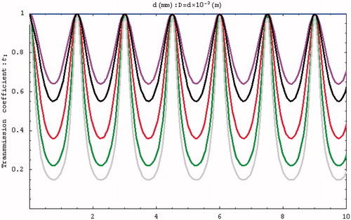
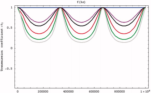
The initial condition was defined as f = 0.5 MHz, and the influences of D and tI were determined by changing S12. indicates that a higher S12 increases the reflectivity, while shows that the transmission efficiency at 0.5 MHz is lowest when the tube length is 2.25 mm.
Figure 4. Relationship between transmission coefficient and frequency (S12 = m × 1, with m = 1, 2, 3, 4, 5, and 5.4/2.4 indicated in blue, purple, red, green, grey, and black, respectively).
Study designs involving bilateral expansion and contraction tubes (as mentioned above) as well as unilateral expansion and contraction tubes were considered when deciding the optimal type of multi-section tube to use. A multi-section path with a flat edge can be designed by combining these tube types.
Simulations were performed using a combination of the acoustic-piezoelectric interaction module and the bioheat transfer module in COMSOL (a multi-physics simulation package). The acoustic-piezoelectric interaction module sets the vibration mode of the probe as the inward normal acceleration and calculates the intensity and the sound pressure distribution. The bioheat transfer module uses the bioheat transfer equation to calculate the time-varying temperature distribution. The simulation results are relative to the inlet pressure. The sum of the heat flux passing through the inlet transducer is compared against the energy dissipated into the bioheat transfer equation module and the outlet boundary to show the energy delivery efficiency. Acoustic reflection occurs at an interface due to a change in acoustic load, which in this study occurred because of an abrupt change in the cross-section of the structure. Unilateral and bilateral expansion and contraction tubes were found to have the same effects. shows the sound field distribution in a 2.25-cm multi-section expansion tube and the acoustic penetration for different cross-section ratios and three values of S12. A larger S12 ratio results in a lower sound pressure for the wave propagating through the tube. For a design that combines a contraction tube and an expansion tube with the minimum acoustic penetration of a multi-section tube with S12 = 3, the output sound pressure is still smaller than the incident sound pressure (). These results show that the sound pressure can be reduced by changing the acoustic cross-sectional area irrespective of whether a contraction or expansion tube is used. This study considered using a flat sound-blocking structure to avoid energy accumulation in the ribs. A comparison of the results in (for S12 = 2 and a unilateral expansion tube) and (for S12 = 0.5 and a unilateral contraction tube) reveals the reduced sound transmission that reduces the adverse effects of the penetrating acoustic pressure.
Figure 5. Sound field distribution of a bilateral expansion tube for (a) , (b)
and (c)
(x in m, y in Pa).
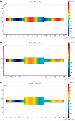
Figure 6. Sound field distribution of a bilateral contraction tube for .
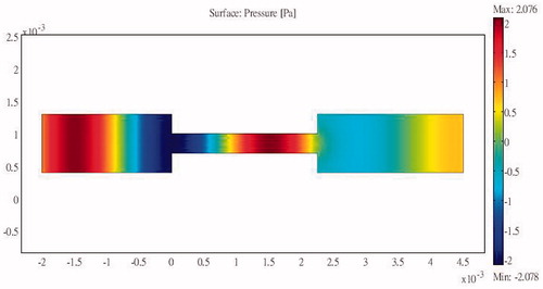
Figure 7. Sound field distribution of a unilateral expansion tube for (x in m, y in Pa).
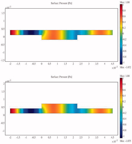
Figure 8. Sound field distribution of a unilateral contraction tube for (x in m, y in Pa).
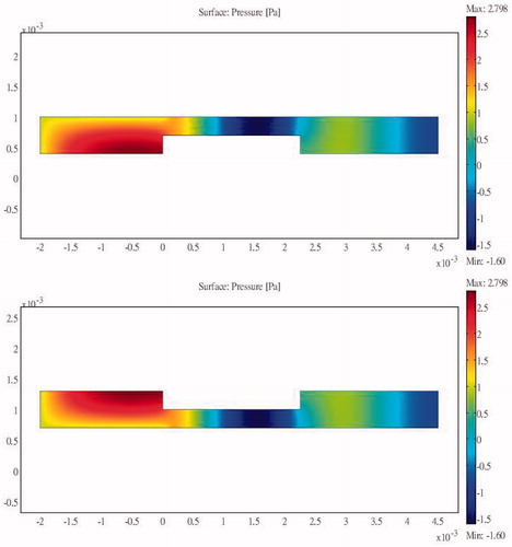
The results of the simulations indicate that a larger ratio of cross-sectional areas reduces the propagation of acoustic pressure when either expansion or contraction tubes are used.
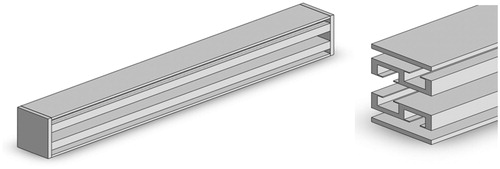
combines the results shown in , and shows how the edge of the flat region interferes with the other regions in terms of propagation of the sound energy. Considering the size of pig ribs and the placement angle for a width of 8.4 mm, the thinner end of the rib is about 3.5 mm and the thickness of the structure frame is about 0.3 mm. The design of the sound-blocking structure is shown in . The length of the sound-blocking structure was based on probe size and bone length. The peripheral part is 9 mm long to minimise reflectivity at that point. This design has the lowest impact on the acoustic energy passing between the ribs. The length of the overall sound-blocking structure can be adjusted depending on probe size and bone length in individual applications. The overall structure is shown as 3D diagrams in .
Figure 9. Basic concepts of the 2.25-cm sound-blocking structure.
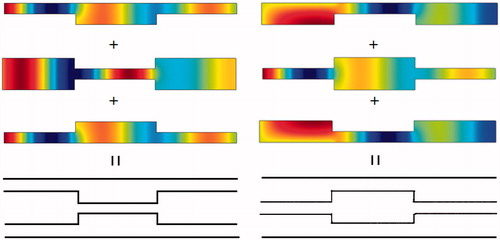
Figure 10. Innovative sound-blocking structure for placement in front of the ribs.
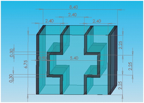
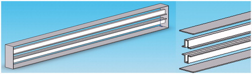
Figure 11. 3D views of the blocking structure frame.
The resonance chamber design
From Equation 12 it is possible to design a structure to filter out a 0.5 MHz excitation signal under water.
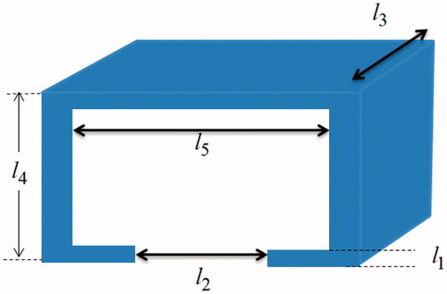
Refer to for the corresponding dimensions, equation Equation12(12)
(12) then requires that
(16)
(16)
where l3 was cancelled during the operation. The settings of l1 = 0.1 mm, l2 = 1.8 mm, l4 = 3.6 mm, and l5 = 1.14 mm fulfilled the requirements (31), and hence were used for the design.
Figure 12. Dimensions of the resonator.
The basic structure of the design consists of a sound path with a resonator cavity attached to the side. and show the basic design configurations with the resonator attached unilaterally at the upstream and downstream sections of the channel, respectively, along with the internal sound intensities generated when sound excitation is applied at the input end. The sound intensity at the output end is significantly reduced in both designs; the energy accumulates within the resonator and is dissipated via internal friction.
Figure 13. Sound intensity distribution for a unilateral side resonance structure in the upstream region of the tube.
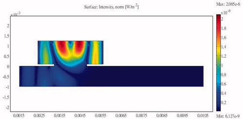
Figure 14. Sound intensity distribution for a unilateral side resonance structure in the downstream region of the tube.
The structures in and would be awkward to implement; therefore, we propose an alternative structure () with a smooth outer profile whose design is based on a combination of the structures shown in and . The protruding resonator caused interference in sound energy propagation with the flat area along the other edges. The design minimises this interference while preserving the sound-blocking characteristics. COMSOL was again used to perform simulations to determine the pressure distribution relative to the inlet pressure. The length of the overall side resonance structure can be adjusted according to probe size and bone length. The structure can also be designed to have an arcuate shape to fit different patients. The overall structure is shown as 3D diagrams in .
Figure 15. Minimising interference using a combination of side resonance structures.
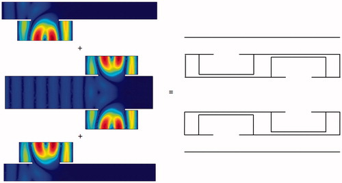
Figure 16. 3D diagrams of the combined side resonance structures.
The designs at this stage are all based on two-dimensional analyses in accordance with the strip design of the structure required for rib protection. The initial experimental set-up showed that the cost of the straight block structures was not excessive. However, as ribs are curved, the cost of making customised curved structures could be a source of additional expense. However, initial trials with the straight structure showed it to be very effective.
Full path acoustic model simulation
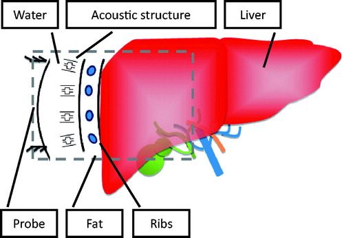
The full path simulation considered all the media types encountered in the acoustic pathway during HIFU treatments. Path media include fat, ribs, and the liver (the study took water to be the background acoustic medium). The size of the ribs in the simulations was based on the average size of the experimental pig ribs.
The incident sound field is based on the excitation model of the piezoelectric material at a particular frequency. An excitation of 500 V was applied to the piezoelectric material to provide an acoustic source in the simulations. This study used an arc-shaped probe to focus the acoustic energy. With the inclusion of the proposed sound-blocking structure, the overall sound field analysis allowed the energy distribution to be analysed along the full sound path. The specific modelling method was compatible with the size and structure of pig ribs, which are elliptical and have aspect ratios of 1–2 and a spacing of about 2 cm. The parameters for the material also follow those of the pig ribs. Taking the focus probe as the incident acoustic source allows energy to be focused behind it. This study applied this principle to the pig rib model to determine design standards and design an innovative sound-blocking structure that would avoid energy accumulation in the ribs. A schematic of the structural analysis method is shown in .
Figure 17. Overall schematic diagram of the structure and the sound propagation path.
The simulation includes situations with and without the sound-blocking structure. The material parameters such as the elasticity matrix, the coupling matrix, and the relative permittivity of the piezoelectric transducer (PZT5-H) are provided in , while the media parameters along the sound pathway are given in .
Table 1. Elasticity matrix (ordering: x, y, z, yz, xz, xy), in Pa.
Table 2. Coupling matrix, in C/m2.
Table 3. Relative permittivity.
Table 4. Media parameters along the sound propagation path.
Two types of simulation were performed: (1) a piezoelectric solid model representing the HIFU probe normally used to provide high frequency ultrasound excitation, and (2) a pressure acoustic model, which considered the full sound path including sound transmission through water, the sound-blocking structure, blood, ribs, and the liver. As a compromise between accuracy and computing requirements, the finite element model had 681,203 elements with 995,442 degrees of freedom.
Simulation results
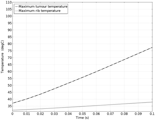
The simulation considered three different conditions, and the results include the pressure and temperature distributions throughout the sound field for (1) HIFU ablation without protection, (2) with expansion muffler protection, and (3) with the novel sound-blocking structure shown in , respectively. Simulation pressure colour bars are normalised from 0 Pa to 5 MPa, and intensity colour bars are normalised from bars set only from 10 °C to 60 °C. Tissues over 60 °C become necrotic and are represented in dark red. The maximum temperature of the tumour in the focusing region and the accumulated temperature of the ribs are important indexes when comparing the different protection methods. The temperature range of the two-dimensional plot was set from 31 °C to 110 °C. The medium parameters are listed in and . The acoustic wave is generated by the ultrasound transducer excited at 0.5 MHz. The average wavelength is 2.99 mm at 25 °C in water. To achieve good simulation results, each wavelength should span at least three meshes [Citation22]. The initial sound pressure of all elements was 0 Pa, the initial temperature of the liver and the tumour was set to 37 °C, that of the ribs and the fat was set to 32 °C, and that of the environment (water) was set to 20 °C.
Figure 18. Sound field simulation in the absence of protection.
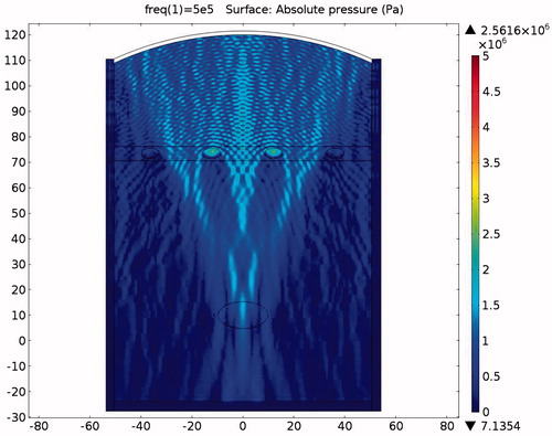
Figure 19. Sound intensity simulation in the absence of protection (x axis is in mm, y axis is in Pa).
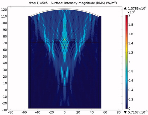
Figure 20. Temperature distribution in the absence of protection after a 0.1-s ablation (x axis is in mm, y axis is in Pa).
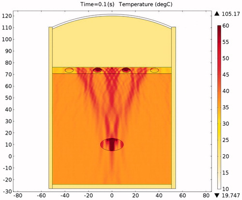
Figure 21. Temperatures of rib and tumour after 0.1-s ablation time.
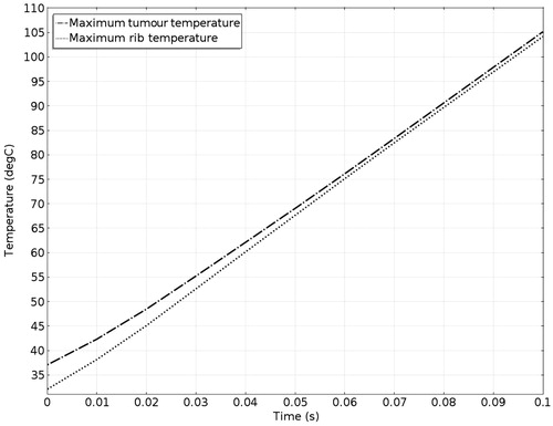
Figure 22. Sound field simulation in the presence of the expansion muffler structure (x axis is in mm, y axis is in Pa).
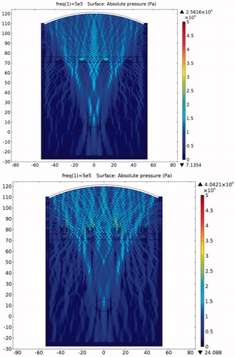
Figure 23. Sound intensity simulation in the presence of the expansion muffler structure (x axis is in mm, y axis is in Pa).
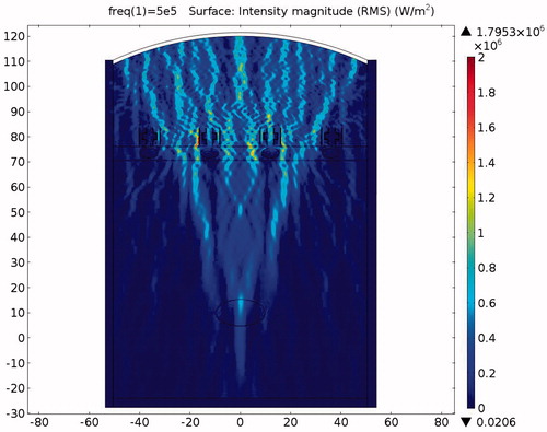
Table 5. Thermal characteristics of various materials.
Table 6. Arterial blood temperature and perfusion rate.
HIFU ablation without protection
The pressure distribution during ablation without the protection device attached is shown in . It can be clearly seen from the picture that the ribs are directly affected by the incident acoustic pressure. The ribs suffer from very strong ultrasonic pressure throughout the entire HIFU ablation region. Because of the strong attenuation by the ribs, very small amounts of acoustic pressure can penetrate through the ribs. Consequently the acoustic pressure distribution within the ribs is larger in the front and continuously decays towards the rear. After some further attenuation, the remaining acoustic pressure penetrates through the water and the tissues to become focused on the tumour area.
The acoustic intensity is proportional to the square of the acoustic pressure and is inversely proportional to the medium density and velocity. illustrates the manner by which the acoustic energy emitted from the transducer propagates mainly along the axis of symmetry. Part of the acoustic energy is absorbed by the ribs and the rest penetrates through the tissues and focuses on the tumour. shows the temperature field of the HIFU ablation without the rib protection device. It can be observed that the rib and tumour temperature reach over 60 °C after a 0.1-s ablation time. The 2-D plot shown in shows that rib temperature rises rapidly and approaches that of the tumour. The maximum temperature reached by the tumour is 105.17 °C, while the maximum temperature reached by the ribs is 104.19 °C. This results in undesirable rib necrosis during tumour treatment.
HIFU ablation with expansion chamber muffler protection
The pressure distribution during ablation with acoustic expansion muffler structure protection is shown in . Acoustic pressure can be seen to be smaller at the expansion muffler outlet than at the inlet, although some pressure penetration occurs to the ribs. shows the intensity distribution and its variation in magnitude according to the medium. shows the temperature distribution during HIFU ablation. The ribs are still damaged after a 0.1-s ablation time, although the temperature is not as high as when no protection device is used. clearly shows the differences in temperature between the tumour and the ribs. The rib temperature increases at a slower rate than that of the tumour. If the ablation time is kept at about 0.02-s, the tumour would be cauterised without damaging the ribs. shows that the maximum temperatures achieved within the tumour and the ribs were 40.75 °C and 46.84 °C, respectively. This is an acceptable temperature range, but if the ablation time is increased beyond 0.02 s, then the ribs will be damaged. Thus there is still room to improve the design to allow longer ablation times.
Figure 24. Ablation temperature distribution in the presence of the expansion muffler structure after a 0.1-s ablation (x axis is in mm, y axis is in Pa).
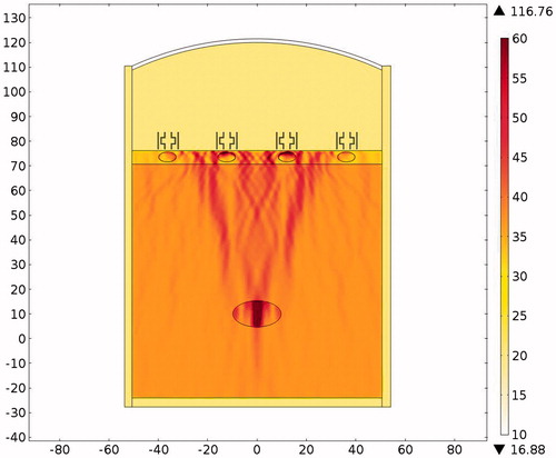
Figure 25. Temperatures of the ribs and the tumour after a 0.1-s ablation.
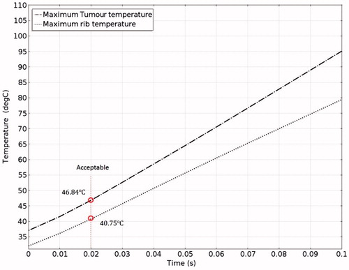
Table 7. Temperatures of rib and tumour after a 0.02-s ablation.
HIFU ablation with resonator chamber protection
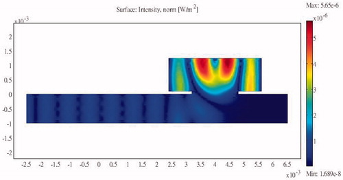
The pressure distribution during ablation with acoustic resonator structure protection is shown in . To allow easier observation, presents the detailed sound pressure distribution near the resonator-based structure. The pressure distribution within the acoustic resonator structure is similar to that in , indicating the effectiveness of the design outlined in the analysis section above. The acoustic pressure exhibits a similar mode in the cavity of the acoustic blocking structure, indicating that the acoustic field resonates within the structure. The acoustic pressure decays significantly from the inlet to the outlet. Only a small amount of acoustic pressure penetrates through the acoustic blocking structure. The acoustic intensity distribution and the temperature distribution in also shows the same result. shows the temperature variation for ablation times ranging from 0 to 0.1 s. The temperature of the tissues depends on the ablation time. The temperature of the tumour increased from 37.03 °C to 77.37 °C while the rib temperature increased by only 5.87 °C. The detailed temperature distribution around the tumour and the rib at different times is shown in . This result indicates that the ribs, when placed under the protection of an acoustic blocking structure, are protected while the tumour is successfully ablated. The results also show that the resonator design is better than the expansion chamber design.
Figure 26. Sound field simulation in the presence of the resonator structure (x axis is in mm, y axis is in Pa).
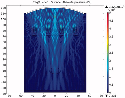
Figure 27. Close-up view of the pressure distribution around a single rib and resonator structure (x axis is in mm, y axis is in Pa).
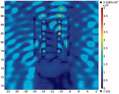
Figure 28. Sound intensity simulation in the presence of the resonator structure (x axis is in mm, y axis is in Pa).
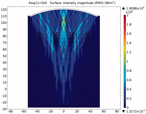
Figure 29. Temperature distribution in the presence of the resonator structure after a 0.1-s ablation (x axis is in mm, y axis is in Pa).
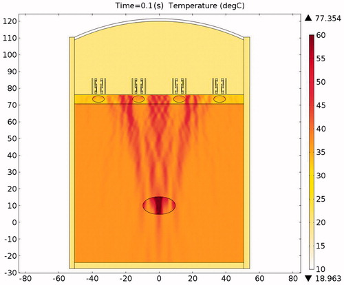
Figure 30. Temperatures of the rib and tumor after a 0.1-s ablation time.
Experiments
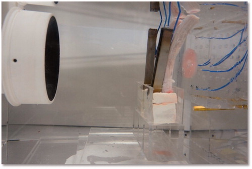
To verify the proposed concept, we established the experimental set-up shown in . The ultrasound-blocking structure was designed according to the design depicted in and . The structural dimensions are within the common working range and are not very difficult to manufacture. The ultrasound transducer has a diameter of 10 cm and a radius of curvature of 12 cm. The piezoelectric transducer driver is capable of outputting a 0.4–0.6-MHz signal with an output power ranging from 0 to 100 W. In the following experiments the output power of the transducer was set to 50 W. Instead of using human ribs we used porcine ribs, which were placed in front of a phantom. The thermocouples were inserted in front of the ribs and within the phantom near the intended focusing zone and in its vicinity. A photograph of the actual experiment set-up is shown in .
Figure 31. Experimental setup for HIFU rib sparing tests (DAQ: Data Acquisition, PC: Personal Computer).
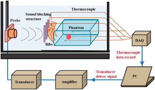
Figure 32. Ablation with the rib protective structure in place.
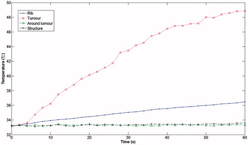
and show the results of the measurements took from the shows the measurements obtained without the protection structure in place, which demonstrate that, after a 60 seconds ablation time, the temperature of the ribs had already reached 73 °C while the temperature in the region of the tumour had reached 51 °C. The temperature of the surrounding area remained constant at the initial ambient temperature of 33 °C. With the rib protection device in place (), it can be clearly seen that when the ambient temperature was held at 33 °C, the focusing region (the tumour region) reached a temperature of 49 °C, whereas the rib temperature reached a temperature of only 36.5 °C after an ablation time of 1 min.
Figure 33. Ablation without protection.
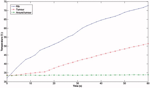
Figure 34. Ablation with the rib protective structure in place.
Discussion
This study compared three types of treatment scenarios and the pressure distribution during HIFU ablation treatment (1) without protection, (2) with expansion muffler protection, and (3) with the proposed resonator structure. The results indicate that without protection the ribs reached a temperature of about 104.19 °C (due to their large attenuation) because of the large amount of acoustic energy that was absorbed and converted to heat. Thus the risk of rib necrosis can be judged to be high during HIFU ablation treatment.
When the expansion muffler was added at 0.02 s after the initiation of the pulse the temperature of the tumour reached 40.75 °C while the temperature of the rib reached 46.87 °C (). Thus the structure prevents energy accumulation that could otherwise result in the destruction of the rib tissue, while at the same time it allows energy to propagate past the bone to the target tissue. In this case ablation time should be set carefully. The centralised location of the high-energy region is already apparent in this case. The acoustic pressure was higher in front of and lower at the rear of the muffler ().
The acoustic pressure distributions throughout the sound field in the presence of the proposed novel resonator are shown in , and indicate that the pressures exerted on the ribs are much smaller than those observed in and . From the results of the temperature simulation () we determine that the tumour temperature reached about 77.37 °C while the rib temperature reached only 37.86 °C. When these results are compared with those obtained without protection () and with the expansion muffler (), it is clear that the resonance chamber is better because it does not damage the ribs or require delicate timing of ablation (). The temperature distributions after an ablation time of 0.1 s are shown in . These results show that the proposed ultrasound resonator structure is safer and more efficient than the other solutions proposed. Moreover, when the resonator chamber is used, the temperature difference between the tumour and the ribs is large and the system is less sensitive to ablation time.
Table 8. Temperatures of rib and tumour after a 0.1-s ablation.
A careful examination of the results of the two protection structures shows the expansion muffler generates higher acoustic pressure near the probe than the resonator structure. The expansion muffler reflects more energy back to the applicator than the resonator structure, which could cause harm to the transducer or person performing the operation. However, the amount of reflected energy can be controlled by adjusting the proportions of the expansion section because this will change the impedance of the sound path. To allow for design flexibility we have left room in our structure for fine-tuning the proportions of the expansion section. The resonator-muffler, on the other hand, dissipates ultrasound energy through the resonance chamber and reflects very little energy back to the operator. However, the dissipated heat has to be carried away by convection. Fortunately, the sound-blocking structure is immersed in water, which is, by its very nature, an ideal medium for convection. It is important to note that changing the chamber dimensions also changes the impedance of the sound path and allows further tuning of the amount of energy passing through the structure.
The resonator structure proposed in this study are inexpensive to make and would be easy to apply in a clinical setting. The experimental results showed that, without a protective device, after an ablation time of 1 min, the rib reached 73 °C while the tumour region only reached 51 °C. By contrast, with the same ablation time, the rib-sparing ultrasound protective device resulted in a tumour region temperature of 49 °C and a rib temperature of 36.5 °C.
Although the straight structure is not very hard to manufacture, the phased-array method currently in use would appear to have the advantage that no custom-made structure is required to fit different patients. Also, ribs are curved, and at this point, the authors have not been able to determine the cost of manufacture of curved structures. However, the experiment using the straight structure in front of the curved porcine rib showed that satisfactory results can be obtained. Further study will be required to examine the effects of structure dimensions on the efficiency of the devices. With the advent of the increasing popularity of custom-made products within new manufacturing facilities, the proposed structures could have great potential as practical clinical tools.
Conclusions
This study investigated novel sound-blocking structures that can be placed directly in front of the rib cage for transcostal HIFU. The method can be adapted to bones of any thickness or shape, and the innovative sound-blocking structure can be reused, making it cheaper and easier to use than currently available methods that require sophisticated equipment and complicated computations. The mechanical structure can be designed to conform to differences in bone geometry among patients.
Two types of blocking mechanism were proposed: (1) an expansion muffler, which has the adverse effect of excessive energy reflection and requires very accurate ablation time control, and (2) a resonator-muffler structure that dissipates part of the energy hitting the ribs and achieves good temperature distribution. The study showed that, irrespective of the expansion chamber or the resonator chamber employed, the penetrated energy still forms a focal zone for ablation. A mathematical model was constructed for simulation purposes. The simulation showed that positioning the sound-blocking structure in the ultrasound pathway avoids heat accumulation on the ribs while still allowing the acoustic energy to pass around the ribs and form a focal zone for HIFU ablation. The experimental results showed that without protection the rib temperature reached 73 °C while the tumour reached 51 °C. By contrast, with protection the tumour reached 49 °C and the ribs reached 36.5 °C, a temperature that would not be considered to cause damage to the ribs.
Declaration of interest
This research was funded by the Ministry of Science and Technology, Taiwan, under Project No. 98-2221-E-002-180-MY3. The authors alone are responsible for the content and writing of the paper.
References
- Maloney E, Hwang JH. Emerging HIFU applications in cancer therapy. Int J Hyperthermia 2014;1–8. PMID: 25367011
- Let’s beat cancer sooner. Cancer Research UK, 2013. Available at: http://www.cancerresearchuk.org/cancer-help/about-cancer/treatment/other/high-intensity-focused-ultrasound-hifu (accessed 18 December 2013)
- ter Haar G, Coussios C. High intensity focused ultrasound: Past, present and future. Int J Hyperthermia 2007;23:85–7
- Zhou YF. High intensity focused ultrasound in clinical tumor ablation, World J Clin Oncol 2011;2:8–27
- Seip R, Chen W, Tavakkoli J, Frizzell L, Sanghvi N. High-intensity focused ultrasound (HIFU) phased arrays: Recent developments in transrectal transducers and driving electronics design. Proceedings of the 3rd International Symposium on Therapeutic Ultrasound, 22–25 June 2003, Lyon, France
- Schmitz AC. Towards MRI-guided high intensity focused ultrasound of breast cancer. Enschede, Netherlands: Universiteit Utrecht; 2011
- Nabi G, Goodman C, Melzer A. High intensity focused ultrasound treatment of small renal masses – clinical effectiveness and technological advances. Indian J Urol 2010;26:331–7
- Hsu MC, Hsu CChen YY, Lin WL. P2G-2 High intensity focused ultrasound thermal therapy for liver tumor with respiration motion.In IEEE Ultrasonics Symposium, 2006, Vancouver, Canada, pp 1734–7
- Dervishi E, Larrat B, Pernot M, Adam C, Marie Y, Fink M, et al. Transcranial high intensity focused ultrasound therapy guided by 7 Tesla MRI in a rat brain tumour model: A feasibility study. Int J Hyperthermia 2013;29:598–608
- Khokhlova TD, Hwang JH. HIFU for palliative treatment of pancreatic cancer. J Gastrointest Oncol 2011;3:175–84
- Laugier P, Haiat G. Bone Quantitative Ultrasound. Springer: Dordrecht Heidelberg, London, New York; 2011
- Cheng S-Q, Zhou X-D, Tang Z-Y, Yu Y, Wang H-Z, Bao S-S, Qian D-C. High-intensity focused ultrasound in the treatment of experimental liver tumour. J Cancer Res Clin Oncol 1997;123:219–23
- Azhari H. Basics of Biomedical Ultrasound for Engineers. Appendix A. Typical acoustic properties of tissues. Wiley-IEEE Press; 2010. pp 313–14
- Fry WJ, Fry RB. Determination of absolute sound levels and acoustic absorption coefficients by thermocouple probes – experiment. J Acoust Soc Amer 1954;26:311–17
- Bobkova S, Gavrilov L, Khokhlova V, Shaw A, Hand J. Focusing of high-intensity ultrasound through the rib cage using a therapeutic random phased array. Untrasound Med Biol 2010;36:888–906
- Civale J, Clarke R, Rivens I, Ter Haar G. The use of a segmented transducer for rib sparing in HIFU treatments. Ultrasound Med Biol 2006;32:1753–62
- Liu H-L, Chang H, Chen W-S, Shih T-C, Hsiao J-K, Lin W-L. Feasibility of transrib focused thermal ablation for liver tumors using a spherically curved 2D array: A numerical study. Med Phys 2007;34:3436–48
- Qiao S, Shen G, Bai J, Chen Y. Transcostal high-intensity focused ultrasound treatment using phased array with geometric correction. J Acoust Soc Amer 2013;134:1503–14
- Lu M, Wan M, Xu F, Wang X, Chang X. Design and experiment of 256-element ultrasound phased array for noninvasive focused ultrasound surgery. Ultrasonics 2006;44:325–30
- Aubry J-F, Pernot M, Marquet F, Tanter M, Fink M. Transcostal high-intensity focused ultrasound: Ex vivo adaptive focusing feasibility study. Phys Med Biol 2008;53:2937–51
- Cochard E, Prada C, Aubry J, Fink M. Ultrasonic focusing through the ribs using the DORT method. Med Phys 2009;36:3495–503
- Gelat P, ter Haar G, Saffair N. Modeling of the acoustic field of a multi-element HIFU array scattered by human ribs. Phys Med Biol 2011;56:5553–81
- Gelat P, ter Haar G, Saffari N. The optimization of acoustic fields for ablative therapies of tumours in the upper abdomen. Phys Med Biol 2012;56:8471–97
- Li F, Feng R, Zhang Q, Bai J, Wang Z. Estimation of HIFU induced lesions in vitro: Numerical simulation and experiment. Ultrasonics 2006;44:e337–40
- Heydari M, Jahed M. Prediction of temperature distribution and volume of lesion during HIFU therapy. In: IEEE 2009 Sixth International Conference on Information Technology: New Generation. Las Vegas, NV, 27–29 April 2009, pp 1468–73
- Ilyin S, Bobkova S, Khokhlova V, Gavrilov L. Simulation of thermal lesions in biological tissues irradiated by high-intensity focused ultrasound through the rib cage. Phys Wave Phenom 2011;19:62–7
- Prakash P, Diederich CJ. Considerations for theoretial modelling of thermal ablation with catheter-based ultrasonic sources: Implications for treatment planning, monitoring and control. Int J Hyperthermia 2012;28:69–86
- Marquet F, Aubry J, Pernot M, Fink M, Tanter M. Optimal transcostal high-intensity focused ultrasound with combined real-time 3D movement tracking and correction. Phys Med Biol 2011;56:7061–80
- Kim Y-S. Advances in MR image-guided high-intensity focused ultrasound therapy. Int J Hyperthermia 2014;1–9. PMID: 25373687
- Prasad MG, Crocker MJ. Studies of acoustical performance of a multi-cylinder engine exhaust muffler system. J Sound Vibr 1983;90:491–508
- Funkhouser T, Tsingos N, Carlbom I, Elko G, Sondhi M, West J. Modeling sound reflection and diffraction in architectural environments with beam tracing. Paper presented at Forum Acusticum, Seville, Spain, 2002
- Bilawchuk S, Fyfe K. Comparison and implementation of the various numerical methods used for calculating transmission loss in silencer systems. Appl Acoust 2003;64:903–16
- Kagawa Y, Yamabuchi T. Finite element simulation of a composite piezoelectric ultrasonic transducer. IEEE Trans Sonics Ultrason 1979;26:81–7
- Amin V, Wu L, Roberts R, Thompson RB, Ryken T. HIFU therapy planning using pre-treatment imaging and simulation. Fifth International Symposium on Therapeutic Ultrasound. AIP Conf Proc 2006;829:206–12
- Burtnyk M, Chopra R, Bronskill M. Simulation study on the heating of the surrounding anatomy during transurethral ultrasound prostate therapy: A 3D theroretical analysis of patient safety. Med Phys 2010;37:2862–75
- Do K-H, Tsu T-M, Gun S-F. Basic Acoustics. Nanking: Nanking University Press; 2001
- Wissler EH. Pennes’ 1948 paper revisited. J Appl Physiol 1998;85:35–41
- Pennes HH. Analysis of tissue and arterial blood temperatures in the resting human forearm. J Appl Physiol 1948;1:93–122
- Nyborg WL. Heat generation by ultrasound in a relaxing medium. J Acoust Soc Amer 1981;70:310–12
- Koo J, Kleinstreuer C. Viscous dissipation effects in microtubes and microchannels. Int J Heat Mass Transfer 2004;47:3159–69