To the Editor,
One commonly used image-guided radiation therapy (IGRT) correction strategy is the adjustment of the target point to compensate for the patient setup error. This target point correction (TPC) is realized by a shift of the treatment couch, resulting in a compensation of the rigid component of the misalignment only. Yet, setup errors consist of translational, rotational and deformation components. Therefore, even if a couch shift is performed prior to each treatment fraction, residual displacements of local anatomical structures remain.
The TPC parameters vary depending on the size and location of the box used for registration. The optimal parameters need to be determined so that the initial dose prescription in the target volume and organs at risk (OARs) are maintained over the treatment course, even despite residual misalignments.
In daily routine, often an optimal alignment of the boost is considered most important to assure target coverage, since the majority of recurrences in head-and-neck cancer occur within this region [Citation1]. This fact favors the restriction of the registration region to the boost only. On the contrary, in the case of nodal tumor spread to several cervical levels, it can be considered more important to align all nodal regions as best as possible. This can be achieved using a large registration box encompassing the entire neck.
The aim of this study was to evaluate the differences in the TPC vectors resulting from the CT alignment of two different registration regions: The first vector was derived from a registration of a small box focused to the boost only. The second vector resulted from a registration of a large box which included the entire cervical and supraclavicular node regions. As well, for both approaches, the differences in the dose coverage of the clinical target volume (CTV) and the dose to the spinal cord were investigated.
Material and methods
Patients, target volume definitions, IMRT plans
Three postoperative head-and-neck cancer patients with daily kilo-voltage control-CTs were analyzed. These patients were chosen because they represent different characteristics occurring in head-and- neck cancer patients: Patient 1 was a patient with a small boost volume, hence, the size between the two RBs showed a large difference. In patient 2 the CTV shrank during the treatment course due to postoperative edema shrinkage. Subsequently, the boost contour was manually adjusted on all control-CTs. Patient 3 is a head-and-neck cancer patient showing large absolute positioning deviations.
All patients were treated with a linear accelerator (Siemens Artiste, USA), combined with an in-room, single-slice spiral CT-scanner. Twenty-eight to 32 CT-scans per patient with a resolution of 0.98 × 0.98 × 3.0 mm3 in patients 1 and 3, and 0.98 × 0.98 × 2.0 mm3 in patient 2 were evaluated.
An integrated boost technique with two CTVs was used: A therapeutic CTV (“boost”, CTV) encompassing the pre-surgical gross tumor volume (GTV), and a larger, prophylactic CTV (pCTV) enclosing the supraclavicular and the cervical lymph nodes. Both CTVs were extended by a CTV-to-PTV margin of 3 mm to define the respective PTV and pPTV [Citation2]. This study focuses on the dose coverage of the CTV only. Dose prescription to the PTV (pPTV) was 70.4 Gy (57.6 Gy) in 32 fractions. The maximum dose to the cervical cord was limited to 40 ± 1 Gy.
Target point correction (TPC) strategies
Two different TPC approaches were investigated: rigid image registration based on mutual information was used to determine the 3D-vector as parameter for the TPC. Three translational and three rotational corrections were calculated. For the TPC the calculated rotational errors were neglected to simulate a simple treatment couch shift widely used in clinical routine. The area used for registration was restricted using a registration box (RB). Two differently sized RBs were defined: the large RB contained the pPTV, the small RB contained the PTV. A registration with the large/small RB was performed to derive the parameter for the first/second TPC vector. Then the dose calculation using the initial treatment plan with the corrected target points was performed on each control-CT. Since daily kilo-voltage control-CTs were available, it was possible to perform a non-fragmentary evaluation of the dosimetric changes over a full treatment course.
Re-contouring of the cord and CTV on each control-CT was necessary to subsequently calculate the fraction DVHs. CTV re-contouring was performed by a rigid transformation of its initial contour using the registration result of the small RB, including rotations. To generate the new spinal cord contours a quasi-elastic approach was applied using slice-wise rigid contour propagation within the x-y plane.
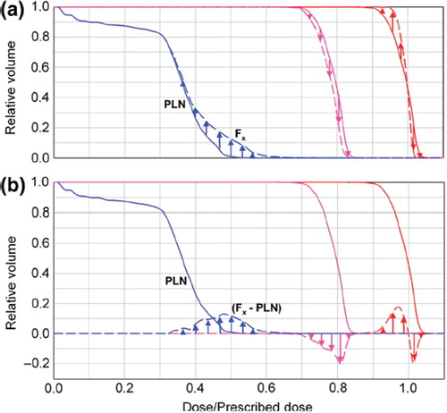
For illustration of the resulting dose differences in respect to the planned dose, the planning DVH was subtracted from the DVHs generated for each fraction ().
Figure 1. Schematic diagram for representation of the DVHs for three exemplary curve progressions. PLN: planning DVH. F3: fraction 3. A positive curve progression (e.g. indicated by blue arrows) implies that more volume of this structure receives the respective dose and vice versa. The fraction prescriptions were scaled to the prescribed dose of 70.4 Gy.
Results
TPC parameters
The use of the differently sized RBs resulted in vectors with different magnitudes and directions. In general, the length of the TPC vectors resulting from a registration with the small RB exceeded those from the large RB (). The magnitude of the difference of both vectors was calculated for all fractions (). The difference between the vectors reflects the local residual misalignment of the CTV after a couch correction based on a rigid registration using the large RB.
Figure 2. The component parallel to the x (right-left)-y (anterior-posterior) plane of the correction vectors are plotted for both IGRT approaches using the small and large registration box (RB). For all fractions and patients, the resulting vectors are plotted in blue for the small RB and in red for the large RB.
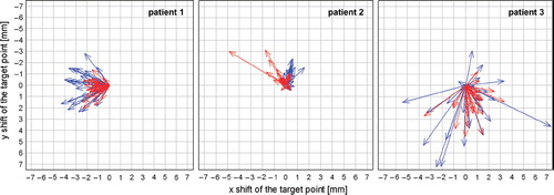
Figure 3. Magnitude of the difference of the vectors resulting from a registration of the small and the large registration box. Upper panel: Presented is the range (min, max) of the distribution over all fractions. Additionally shown is the frequency in percent of the fractions with a difference bigger than 2 mm between both couch shifts. Lower panel: Exemplary illustration of the differences of these vectors for patient 2.
In patient 1 the range of the values was rather small, with a maximum difference of the vectors of only 2.9 mm. Nevertheless, the misalignment of the CTV in this patient still accounted for more than 2 mm in 72% of all fractions. In contrast, in patient 2 only in 38% of all fractions the difference of the vectors was greater than 2 mm. However, the values showed a large range with single fractions of residual CTV positioning errors of up to 7 mm.
Resulting dose differences
In all three patients, the differences in the CTV dose coverage were small, < 1 Gy. This was expected, since the CTV was extended by a CTV-to-PTV margin of 3 mm. Thus the dosimetric effects resulting from positioning variations of the CTV were attenuated due to a larger distance of the CTV to the high-dose gradient.
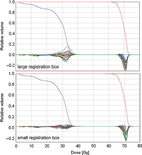
Considering the dose to the spinal cord, it was expected that the large RB results in a better alignment of the spinal cord, since all vertebras were included in the RB. However, in all three patients, the deviations of the fraction DVHs, in respect to the planning DVH, showed a larger variation using the large RB. This means that in more fractions, a bigger portion of the cord volume received a higher or a smaller dose than planned using the large box. The DVHs showing this larger variation was plotted for patient 1 in . In terms of maintaining the maximum dose of the planning situation, the results revealed only a small difference for the cord of about 1 Gy over a full treatment course between the two IGRT strategies.
Figure 4. Planning DVHs of the spinal cord (blue), CTV (red) and fraction DVHs (plotted as illustrated in ) for the two correction approaches, illustrated for patient 1.
Discussion
Patient positioning of head-and-neck cancer patients is challenging due to deformations, therefore it is the subject of ongoing research [Citation3]. Since positioning variations and deformations impact the dose coverage of the target volumes and OARs [Citation4], IGRT correction strategies are widely used to maintain the planned dose distribution as best as possible. An IGRT correction strategy is realized by a treatment couch shift using a 3D vector derived from a rigid registration. In our study, these 3D-vectors differed considerably if two alternatively sized boxes were used for registration. Similar results were found in a comparable alignment study in which a focused, marker-based correction was compared with a correction aligning the cervical vertebral bodies [Citation5]. The difference between the vectors can be a measure of the magnitude of deformations. A smaller deviation between the vectors indicates that the occurrence of deformations in the entire neck anatomy is less likely. Thus, if a setup error mainly consists of a rigid component, the registration using the large and small RB would lead to approximately the same result. The magnitude of the difference of these vectors converges to zero in this case.
In case of applying a large RB, the positional variations of all structures included in this box contribute to the resulting correction parameters. Thus, more distant structures also contribute to the registration process while the impact of the boost region to the registration result is reduced. The larger image may contain more deformed anatomy in its periphery, which can impact the registration result. In contrast, if a smaller RB is focused on a certain structure only, the alignment of this structure is more accurate. To ensure local tumor control a proper alignment of the boost is important, since the majority of tumor recurrences occur in or close to this region [Citation1]. Still it needs to be kept in mind that residual misalignments of peripheral head-and-neck structures remain due to deformations. A correction of these remaining errors can only be realized using daily re-planning, which still is a time-consuming procedure. It is also important to mention that one must be cautious when using the GTV in a preoperative setting as an alignment target, since asymmetric tumor shrinkage can affect the geometric relationship of the GTV to the OARs.
Overall, the detected dose differences between the two approaches were small. Considering the whole spinal cord volume, the variation of the difference of the fraction and planning DVH is smaller using the small RB. Thus, as expected, the planned dose distribution of the cord could be better sustained over the treatment course using the small box. The use of this box also provided slightly better results in terms of CTV dose coverage.
The use of one small or one large RB, as evaluated here, represents two possible IGRT scenarios only. In between, there are numerous possibilities to determine the correction vector based on different sizes or even different numbers of RB used in clinic [Citation6]. Yet, due to the small number of patients analyzed, it is not aim of this study to suggest one favorable registration box that is best for all postoperative head-and-neck cancer patients. Instead, the analysis should accentuate that two different registration regions result in unequal correction vectors differing in both, magnitude and direction.
In summary, the choice of the size and location of the region used for registration impacts the IGRT correction vector for the treatment couch shift. The application of these vectors also leads to differences in the dose to the CTV and the spinal cord.
Declaration of interest: The authors report no conflicts of interest. The authors alone are responsible for the content and writing of the paper.
References
- Chen AM, Farwell DG, Luu Q, Chen LM, Vijayakumar S, Purdy JA. Marginal misses after postoperative intensity- modulated radiotherapy for head-and-neck cancer. Int J Radiat Oncol Biol Phys 2011;80:1423–9.
- Chen AM, Farwell DG, Luu Q, Donald PJ, Perks J, Purdy JA. Evaluation of the planning target volume in the treatment of head and neck cancer with intensity-modulated radiotherapy: What is the appropriate expansion margin in the setting of daily image-guidance? Int J Radiat Oncol Biol Phys 2011;81:943–9.
- Mongioj V, Orlandi E, Palazzi M, Deponti E, Marzia F, Stucchi C, . Set-up errors analyses in IMRT treatments for nasopharyngeal carcinoma to evaluate time trends, PTV and PRV margins. Acta Oncol 2011;50:61–71.
- Elstrøm UV, Wysocka BA, Muren LP, Petersen JB, Grau C. Daily kV cone-beam CT and deformable image registration as a method for studying dosimetric consequences of anatomic changes in adaptive IMRT of head and neck cancer. Acta Oncol 2010;49:1101–8.
- Zeidan OA, Huddleston AJ, Lee C, Langen KM, Kupelian PA, Meeks SL, . A comparison of soft-tissue implanted markers and bony anatomy alignments for image-guided treatments of head-and-neck cancers. Int J Radiat Oncol Biol Phys 2010;76:767–74.
- van Beek S, van Kranen S, Mencarelli A, Remeijer P, Rasch C, van Herk M, . First clinical experience with a multiple region of interest registration and correction method in radiotherapy of head-and-neck cancer patients. Radiother Oncol 2010;94:213–7.