
ABSTRACT
Background. Transabdominal ultrasound (TAUS) imaging is currently available for localizing the prostate in daily image-guided radiotherapy (IGRT). The aim of this study was to determine the induced prostate displacement during such TAUS imaging. The prostate displacement was monitored using a novel transperineal four-dimensional (4D) US (TPUS) system.
Material and methods. Ten prostate cancer patients, with a mean age of 68 years (58/76), were US scanned in the computed tomography (CT) room utilizing the Clarity 4D TPUS monitoring system. The patients were asked to comply with a moderate bladder filling protocol. After US-CT fusion, the prostate volume was delineated and used as a reference for weekly US imaging in the treatment room. Immediately after treatment delivery the TPUS monitoring system was set up. During real-time monitoring of the prostate, a conventional 2D probe was applied to simulate a TAUS scan. The time dependent prostate displacements induced by the 2D probe pressure were recorded for the three orthogonal directions. In total 42 monitoring curves with applied 2D probe were recorded.
Results. Data analysis of 42 US scans resulted in pressure induced prostate displacements with mean values (± 1 SD) (mm); inferior (+)-superior (I/S): (−0.1 ± 0.8); left (+)-right (L/R): (0.2 ± 0.7); and anterior (+)-posterior (A/P): (−0.1 ± 1.0). The majority of the displacements were within 1–2 mm. Only two scans (5%) (A/P direction) and 16% of Euclidean distances were larger than 2.0 mm. The largest displacement was 2.6 mm in the anterior direction.
Conclusion. The novel 4D TPUS system was capable of tracking and recording the prostate positional displacements. The study demonstrated that the prostate induced displacements due to applied TAUS IGRT are small, and in most cases clinically irrelevant to prostate radiotherapy.
In external beam radiotherapy for the prostate cancer, it is imperative to minimize damage to surrounding healthy tissues while delivering a high dose to the prostate. As the position of the prostate can vary substantially between treatment fractions and possibly even during treatment delivery [Citation1–3], methods for precise localization on the prostate are warranted. Different kilovoltage (kV) and megavoltage (MV) image-guided radiotherapy (IGRT) methods have been developed. However, the kV and MV imaging modalities have poor soft tissue visualization, therefore, in many clinics, implanted fiducial markers (FM) in the prostate utilized as a surrogate for the prostate localization [Citation4]. However, implanting FMs are an invasive method and not available in all clinics.
Ultrasound (US), a non-ionizing and non-invasive imaging modality, has been introduced as an alternative inexpensive IGRT method. Clinically, two models of US-IGRT systems, intermodal US (BAT system) and intramodal US (Clarity system) have been introduced [Citation5]. In intermodal US, the US images from the treatment room are matched to computed tomography (CT)-reference images, whilst in intramodal US the US images are matched to the US-reference images from the simulation room. Both systems are based on transabdominal US (TAUS) imaging, using a two-dimensional (2D) US probe. Several studies have been conducted comparing the US-based IGRT to the FM-based IGRT [Citation6–10].
One of the disadvantages of TAUS imaging is the inter-operator variability. For example, variations in exerted probe pressure have been reported to have an impact on prostate position in various studies. One study was designed to investigate pressure induced displacement of the prostate by US scanning of a phantom mimicking a male pelvic area [Citation11]. The disadvantage of such tissue-equivalent phantoms is that the static anatomical structures cannot represent the uniqueness of a patient's organs, in which daily variations in bladder, rectal filling, and shape occur. In another approach, volunteers were TAUS scanned using a fixed 2D probe on a robotic arm [Citation12]. The probe was first placed above the pubis symphysis, and moved vertically towards the prostate step by step, acquiring images at each stage. One limitation of this test is that the TAUS scan of the prostate requires a sweep technique, as opposed to only a vertical probe movement. Moreover, a recently published work, based on TAUS scan of volunteers and prostate patients, demonstrated that applied probe pressure may cause up to 8 mm of prostate displacement while applying “strong pressure” [Citation13]. However, it was impossible in the study to observe any prostate displacements while applying “soft pressure” defined as the minimum pressure required for acquiring sufficient image quality. Thus, a study to simulate the daily in-room TAUS IGRT while recording the induced prostate displacement is required, and this was the motive for our study.
Currently, a system based on an automatic mechanically sweeping US probe, the Clarity transperineal US (TPUS) autoscan (Elekta, Stockholm, Sweden), is being introduced into radiotherapy. The system offers 4D real-time tracking of the prostate.
The aim of this study was to determine prostate displacement, due to applied TAUS probe pressure, by continuously 4D monitoring the prostate utilizing the TPUS autoscan.
Material and methods
Patients
Ten prostate cancer patients, with a mean age of 68 years (the age range of 58–76), were scanned weekly by two of six experienced radiation therapists (RTTs), using the TPUS autoscan. The study was approved by the ethical committee according to “World medical association declaration of Helsinki”. Every patient was verbally informed of the objective of the study, and signed a printed statement of informed consent before participation. Furthermore, the patients were instructed to follow a moderate bladder filling protocol, which involved not urinating after leaving their home on their way to their daily radiation treatment. In this study, the US monitoring images were used for research purposes only and not applied clinically. One patient was excluded after 1 fraction owing to his unwillingness to participate anymore. A total of 48 US scans were acquired, from which six US scans were excluded due to inferior image quality.
Clarity ultrasound (US) system
The Clarity US system consists of two mobile US units: one located in the CT simulation room and the second in the treatment room. The two units are connected through a workstation. The workstation was used for prostate delineation, as well as for retrieving the prostate monitoring curves.
The US unit has a console screen, where anatomical structures can be observed and image quality optimized, using different brightness and contrast settings. The unit also has a conventional convex 2D probe and the novel autoscan probe for TAUS and TPUS scanning, respectively (Supplementary Figure 1C, D, available online at http://www.informahealthcare.com/doi/abs/10.3109/0284186X.2015.1061208). Details of the Clarity characteristics, 3D image reconstructions, and system calibration are described in another paper [Citation14]. In short, a ceiling-mounted infrared (IR) camera can track the US probes by monitoring the IR-reflectors attached to them. This is essential for determining the geographical position of the reconstructed anatomical structures.
CT-simulation, autoscan imaging and CT-US fusion
After the CT scan acquisition, the patient was prepared for the US scan using vendor provided knee cushions resting over the autoscan base (a kit to which the autoscan probe was attached) (Supplementary Figure 1A available online at http://www.informahealthcare.com/doi/abs/10.3109/0284186X.2015.1061208). The patient was instructed to remain still during image acquisition. Afterwards, the CT-US image fusion was performed and the prostate gland delineated. Finally, the delineated prostate was approved as a reference volume for subsequent weekly US scans in the treatment room.
Image acquisition and prostate monitoring in the treatment room
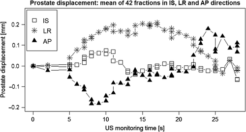
The patient was prepared for daily treatment using FM-IGRT. Immediately after the treatment, the patient was repositioned in preparation for autoscan monitoring. The TAUS scan was simulated, using a 2D probe, while the prostate was continuously monitored using the TPUS autoscan (Supplementary Figure 1E available online at http://www.informahealthcare.com/doi/abs/10.3109/0284186X.2015.1061208). The autoscan, unique in its positioning in relation to the patient's perineal region, and hence outside of the irradiated area, is designed to address the intra-fractional prostate motion during radiation delivery, which was not the aim of this study. During the simulation, no US images were acquired with the 2D probe, i.e. the probe was used as a dummy. However, the trained RTTs were instructed to reproduce the sweeping technique and associated applications of pressure required to acquire adequate US image quality. Furthermore, the RTTs were asked to avoid observing the impact of the pressure on the console screen. The prostate displacements due to the exerted probe pressure were recorded for retrospective analysis. Supplementary Figure 1E shows an example of prostate displacements in inferior-superior (I/S), left-right (L/R), and anterior-posterior (A/P) directions during the 2D probe simulation.
Data collection and statistical analysis
The recorded curves, showing the real-time prostate center of mass (COM) position in all three directions, were retrieved from the Clarity server by one observer (MB). For each curve the displacement as function of time (t) was analyzed relative to a chosen reference position at time t0, a start time shortly before the 2D probe was applied. The overall mean [± 1 standard deviation (SD)], maximum, and minimum of the prostate displacements (relative to the prostate position at t0) were derived for the three directions. Furthermore, the maximum Euclidean distance [Max(D(t))] was computed as the length of the vector between the position of the COM of the prostate at t, the time where the prostate displacement is largest, and t0. The statistical program R was used to analyze the data.
Results
All patients encompassed in this study were cooperative, and none of them expressed any discomfort during the autoscan setup, or from the applied probe pressure. Data analysis of 42 US scans resulted in pressure induced prostate displacements with mean values (± 1 SD) of -0.1 mm (± 0.8 mm), 0.2 mm (± 0.7 mm), and -0.1 mm (± 1.0 mm) in I(+)/S, L(+)/R, and A(+)/P directions, respectively. In addition, the mean of maximum Euclidean distance [(D(t))>] was computed to be 1.3 mm (± 0.7 mm) (). Furthermore, the largest displacement was calculated to be 2.6 mm in the anterior direction and 2.9 mm for D(t). Moreover, the majority of the displacements were found to be within 1–2 mm, and only two scans (5%) (A/P direction) and 16% of Max(D(t)) were larger than 2.0 mm.
Table I. Mean, standard deviations (SD), max of prostate displacement, and displacements larger than 0.5, 1.0, 2.0 mm in all three directions, including Euclidean distance Max(D(t)).
The simulation time employing the TAUS probe was from approximately 15 to 20 seconds (Supplementary Figure 2A–C, available online at http://www.informahealthcare.com/doi/abs/10.3109/0284186X.2015.1061208). The largest dispersal was observed to be in the A/P direction. It was also observed that, after releasing the 2D probe, the prostate could be permanently displaced. Moreover, the mean displacement was shown to be within ± 0.2 mm in all three directions (). Additionally, the mean lateral displacement was about 0.2 mm to the left.
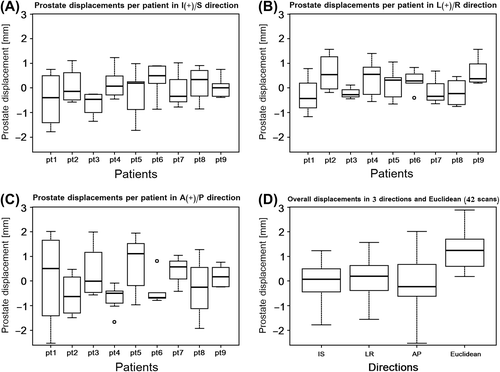
Individual boxplots of all nine patients demonstrated some variations in prostate displacements between them and even for individual patients (). The first patient (pt1) showed the largest day-to-day variations in A/P direction, which can, first of all, be attributed to daily changes in the patient and, second, to the inter-operator pressure variability. Additionally, the boxplot of the overall displacements revealed that the first and the third quartiles were within ± 1.0 mm in all three directions (). Finally, the last boxplot in the figure indicates that the median of the Euclidean distance is about 1.3 mm.
Discussion
Transabdominal US-IGRT in prostate radiotherapy poses some challenges concerning variations in applied probe pressure, and US image interpretation. This can lead to inter-operator variability, in particular among users with little or no US experience. The American Association of Physicists in Medicine (AAPM) emphasizes that US training is essential and can be divided into “initial vendor-provided training and continuous clinical training” [Citation15]. Experienced US users were reported to be more consistent in image acquisition and better at identifying anatomical structures, with less inter-operator variability [Citation16].
This study was designed to determine the influence of TAUS probe pressure on prostate location by utilizing continuous tracking of the prostate employing the novel 4D TPUS autoscan. The accuracy of the prostate monitoring algorithm was validated by Lachaine et al. [Citation17]. They utilized a robotic stage regulator on a US phantom with certain motion patterns. They discovered the mean and standard deviation of the differences between the measured and the regulator to be −0.0 ± 0.2 mm, 0.2 ± 0.4 mm, and −0.2 ± 0.2 mm in the I/S, L/R, and A/P directions, respectively. Another comparison study between the TPUS autoscan system and the Calypso system (Varian Medical Systems, Palo Alto, CA, USA) was performed by Abramowitz et al. [Citation18]. The Calypso system utilizes transponders implanted into the prostate for positional tracking. Abramowitz et al. designed a motorized phantom combined with a prostate-equivalent structure. They found good agreement between the two systems in tracking the embedded prostate-like sphere.
In a study by Fargier-Voiron et al. [Citation13], the impact of probe pressure on prostate displacement was investigated in 16 volunteers and eight patients. They applied soft, moderate and strong TAUS probe pressure to displace the prostate. The induced displacement was then quantified by comparing the position of the prostate under moderate and strong pressure with the prostate position under soft pressure. Thus only the difference between prostate position under soft pressure and the prostate position under moderate or strong pressure could be assessed. They reported the mean and standard deviations of the Euclidean prostate displacements of 2.5 ± 1.2 mm and 3.3 ± 1.6 mm for moderate and strong pressure (relative to soft pressure), which are greatly larger than our Euclidean displacement of 1.3 ± 0.7 mm. Furthermore, Fargier-Voiron et al. measured the maximum prostate displacement to 7.5 mm, using strong pressure, in the inferior direction, compared to our maximal displacement of only 2.6 mm in the anterior direction. However, in our study the measured prostate displacement is between no probe pressure (rest position) and soft probe pressure, which reflects the clinical routine practice of TAUS-IGRT. Another limitation of Fargier-Voiron et al. study was that they only had one TAUS scan per volunteer/patient. In our study we observed large day-to-day variations in pressure displacements for individual patients. In another study, Van der Meer et al. [Citation14] used TAUS probe pressure applied at four levels; no, low, intermediate, and high. As in the study by Fargier-Voiron et al., prostate displacement was measured relative to the US scan applying the least amount of pressure (level of “no pressure”). Applying a low pressure, defined by them as 1 cm skin displacement, sufficient to achieve good image quality, yielded a mean prostate displacement of 0.0 mm, -0.5 mm, and -0.7 mm in I(+)/S, L(+)/R, and A(+)/P directions, respectively. This is comparable to our corresponding sub-millimeter results of −0.1 mm, 0.2, and -0.1 mm. However, Van der Meer et al. reported the average Euclidean distance for the prostate displacement, for low pressure, to be about 3.0 mm, which is larger than our outcome of 1.3 mm. Artignan et al. [Citation12] performed a similar TAUS scan study of volunteers, in which the probe was affixed to a rigid arm, enabling it to move towards the prostate in graded steps. As in the studies by Van der Meer et al. and Fargier-Voiron et al., the reference image was the US scan with the least amount of pressure. Artignan et al. defined a skin displacement of 1.2 cm, of the same magnitude as Van der Meer et al., as sufficient for obtaining adequate US image quality. This pressure resulted in a mean Euclidean vector displacement of 3.1 mm. According to Artignan et al., the displacement is not limited to one direction as was also the case in our study, hence displacements opposite to the direction of the probe pressure were observed.
The result of mean lateral displacement of 0.2 mm () might be explained by the fact that the probe simulation was applied from the right hand side of the patient (Supplementary Figure 1B available online at http://www.informahealthcare.com/doi/abs/10.3109/0284186X.2015.1061208), resulting in the probe being slightly tilted to the right, and hence inducing partial lateral pressure to the left rather than a strictly vertical pressure. Furthermore, the maximal displacement was showed to be 1.2 mm, 1.6 mm, and 2.6 mm in I/S, L/R, and A/P directions, which conforms to a study by Dobler et al. [Citation19] that resulted in corresponding measures of 3.0 mm, 0.8 mm, and 2.8 mm. Dobler et al. investigated displacement of eight iodine seeds, inserted into the prostate during Brachy therapy. The seeds’ positions were tracked by using real-time x-ray simulation while applying TAUS probe imaging using minimum probe pressure. They calculated the absolute displacement of the seeds to be larger than 2.0 mm in 7% of cases for all three directions which was consistent with our obtained results of 0%, 0%, and 5% in I/S, L/R, and A/P directions. In another study, Serago et al. [Citation20] initiated a probe simulated study (no US scans were performed but a Styrofoam dummy was used) using two consecutive CT scans of 16 prostate patients; one without probe simulation and one with probe simulation. They discovered that in nine of the patients there was no measurable prostate movement, and the remaining seven patients had “discernible” displacements. In the patients with prostate displacement, they calculated the average displacement to be 3.1 mm.
Surprisingly, the prostate displacements from our study were less than all previous reported displacements in all directions, except for the results obtained by Dobler et al. The reason might be that Dobler et al. were using a similar method as in our approach, i.e. observing the pressure displacements in real-time and, importantly, not using a US scan with minimal pressure as reference. Most of the other studies were implementing either US/US (Clarity system) or US/CT (BAT system) image matching in order to measure the prostate COM displacements. Van der Meer et al. [Citation14] studied the US/US matching procedure to determine intra-, and inter-operator matching variability through investigating 817 matches of a total of 376 US-scans. They discovered the intra-operator/inter-operator variability (1 SD) to be 0.8 mm/1.8 mm (I/S), 0.7 mm/1.3 mm (L/R), and 1.0 mm/1.4 mm (A/P), respectively. In another study, Langen et al. [Citation21] investigated US/CT matching and found inter- operator variability, among eight observers, to be larger than 2.0 mm (difference between any two matches) in about 50% of the matches in all three directions. The variability in US/US-, and US/CT-matching might adversely affect the accuracy of the measured prostate displacements, and consequently generate larger values.
As with all such studies, there are limitations that offer opportunities for further research. For example, the monitoring algorithm was validated as fairly precise in all cardinal directions, but the sub- millimeter uncertainty, admittedly, corresponded to approximately 10% of the magnitude of the prostate displacements measured in this study. Another limitation was that the TAUS simulations may not reflect a real routine clinical practice, in which anatomical structures can be visualized. We were unable to simultaneously acquire TAUS images while TPUS monitoring, using the same US unit, since another Clarity system was required to do so. In our approach, the operators followed specific instructions to simulate a TAUS scan with the amount of pressure that they would normally use. However, it was not possible to validate that the operators in fact used enough probe pressure. Moreover, although a gentle transperineal attach of the autoscan was carried out with caution, a counter-effect of the probe's head might influence the position of the prostate, and hence changing the magnitude and likewise the direction of the prostate displacements during TAUS simulation. In brief, further similar research, by enrollment of a larger patient population and acquiring larger number of real TAUS scans per patient, are recommended to validate and to strengthen this study.
In conclusion, the novel 4D autoscan US system was able to track and record positional displacements of the prostate. In this study we demonstrated that the displacements of the prostate induced by the applied TAUS IGRT were small, and in most cases clinically irrelevant to prostate radiotherapy.
Supplementary material available online
Supplementary Figure 1 and 2 available online at http://www.informahealthcare.com/doi/abs/10.3109/0284186X.2015.1061208
ionc_a_1061208_sm3733.pdf
Download PDF (3.5 MB)Acknowledgments
We would like to thank all our colleagues who helped to conduct this study; Gullander L. (RTT), Pedersen S. K (RTT), Zarp T (RTT), Jacobsson S (RTT), Pazhang S (radiographer) and Lynnerup V. K (radiographer). This study is a part of PhD research project, supported by Elekta Inc.
Declaration of interest: The authors report no conflicts of interest. The authors alone are responsible for the content and writing of the paper.
References
- Huang E, Dong L, Chandra A, Kuban DA, Rosen II, Evans A, et al. Intrafraction prostate motion during IMRT for prostate cancer. Int J Radiat Oncol Biol Phys 2002;53: 261–8.
- Ghilezan MJ, Jaffray DA, Siewerdsen JH, Van Herk M, Shetty A, Sharpe MB, et al. Prostate gland motion assessed with cine-magnetic resonance imaging (cine-MRI). Int J Radiat Oncol Biol Phys 2005;62:406–17.
- Langen KM, Jones DTL. Organ motion and its management. Int J Radiat Oncol Biol Phys 2001;50:265–78.
- Van der Heide UA, Kotte ANTJ, Dehnad H, Hofman P, Lagenijk JJW, van Vulpen M. Analysis of fiducial marker-based position verification in the external beam radiotherapy of patients with prostate cancer. Radiother Oncol 2007;82: 38–45.
- Cury FLB, Shenouda G, Souhami L, Duclos M, Faria SL, David M, et al. Ultrasound-based image guided radiotherapy for prostate cancer: Comparison of cross-modality and intramodality methods for daily localization during external beam radiotherapy. Int J Radiat Oncol Biol Phys 2006;66:1562–7.
- Johnston H, Hilts M, Beckham W, Berthelet E. 3D ultrasound for prostate localization in radiation therapy: A comparison with implanted fiducial markers. Med Phys 2008;35:2403–13.
- Van den Heuvel F, Powell T, Seppi E, Littrupp P, Khan M, Wang Y, et al. Independent verification of ultrasound based image-guided radiation treatment, using electronic portal imaging and implanted gold markers. Med Phys 2003;30:2878–87.
- McNair HA, Mangar SA, Coffey J, Shoulders B, Hansen VN, Norman A, et al. A comparison of CT- and ultrasound-based imaging to localize the prostate for external beam radiotherapy. Int J Radiat Oncol Biol Phys 2006;65:678–87.
- Scarbrough TJ, Golden NM, Ting JY, Fuller CD, Wong A, Kupelian PA, et al. Comparison of ultrasound and implanted seed marker prostate localization methods: Implications for image-guided radiotherapy. Int J Radiat Oncol Biol Phys 2006;65:378–87.
- Serago CF, Buskirk SJ, Igel TC, Gale AA, Serago NE, Earle JD. Comparison of daily megavoltage electronic portal imaging or kilovoltage imaging with marker seeds to ultrasound imaging or skin marks for prostate localization and treatment positioning in patients with prostate cancer. Int J Radiat Oncol Biol Phys 2006;65:1585–92.
- McGahan JP, Ryu J, Fogata M. Ultrasound probe pressure as a source of error in prostate localization for external beam radiotherapy. Int J Radiat Oncol Biol Phys 2004;60: 788–93.
- Artignan X, Smitsmans MHP, Lebesque JV, Jaffray DA, van Her M, Bartelink H. Online ultrasound image guidance for radiotherapy of prostate cancer: Impact of image acquisition on prostate displacement. Int J Radiat Oncol Biol Phys 2004;59:595–601.
- Fargier-Voiron M, Presles B, Pommier P, Rit S, Munoz A, Liebgott H, et al. Impact of probe pressure variability on prostate localization for ultrasound-based image-guided radiotherapy. Radiother Oncol 2014;111:132–7.
- Van der Meer S, Bloemen-van Gurp E, Hermans J, Voncken R, Heuvelmans D, Gubbels C, et al. Critical assessment of intramodality 3D ultrasound imaging for prostate IGRT compared to fiducial markers. Med Phys 2013;40:071707/1–11.
- Molloy JA, Chan G, Markovic A, McNeeley S, Pfeiffer D, Salter B, et al. Quality assurance of U.S.-guided external beam radiotherapy for prostate cancer: Report of AAPM Task Group 154. Med Phys 2011;38:857–71.
- Fuss M. Daily stereotactic ultrasound prostate targeting: Inter-user variability. Technol CANCER Res Treat 2003;2:161–9.
- Lachaine M, Falco T. Intrafractional prostate motion management with the Clarity Autoscan system. Med Phys Int 2013;1:72–80.
- Abramowitz MC, Bossart E, Flook R, Wu X, Brooks R, Lachaine M, et al. Noninvasive real-time prostate tracking using a transperineal ultrasound approach. Int J Radiat Oncol 2012;84:S133.
- Dobler B, Mai S, Ross C, Wolff D, Wertz H, Lohr F, et al. Evaluation of possible prostate displacement induced by pressure applied during transabdominal ultrasound image acquisition. Strahlenther Onkol 2006;182:240–6.
- Serago CF, Chungbin SJ, Buskirk SJ, Ezzell GA, Collie AC, Vora SA. Initial experience with ultrasound localization for positioning prostate cancer patients for external beam radiotherapy. Int J Radiat Oncol Biol Phys 2002;53: 1130–8.
- Langen K., Pouliot J, Anezinos C, Aubin M, Gottschalk A, Hsu I-C, et al. Evaluation of ultrasound-based prostate localization for image-guided radiotherapy. Int J Radiat Oncol 2003;57:635–44.