Abstract
Abstract: With advances in technical methodology, the grafting of biocompatible conduits may become a viable alternative for the reconstruction of nerve gaps. In this study, electrospinning was used to fabricate nerve conduits (NCs) from poly(L-lactide-coglycolide)-silk fibroin. Conduits or autograft nerves were employed to bridge 10 mm defects in the sciatic nerves of Sprague–Dawley rats. Six weeks after the operation, morphological and functional assessment showed that nerve conduits from PLGA-silk fibroin grafts promoted the regeneration of peripheral nerves. The effects were similar to those obtained using nerve autografts. This method offers a promising alternative to the use of nerve autografts.
INTRODUCTION
The incidence of peripheral nerve injuries has risen in recent years. Peripheral nerve injuries result in profound deficits, including loss of function of the innervated tissue and neuropathic pain. The current clinical standard for treating segmental nerve loss in peripheral nerves is the nerve autograft, in which a segment of non-critical nerve is removed from a secondary (donor) site on the body and used to bridge the missing (recipient) nerve section. This technique has significant drawbacks, including permanent loss of nerve function at the donor site, morbidity at the donor site, and the need for multiple surgeries. These drawbacks have motivated a search for alternate treatment options. For a number of reasons, the development of synthetic materials for artificial nerve grafts is desirable [Citation1]. Synthetic materials have great potential for applications as nerve conduits, as they can be fabricated to have various dimensions, degradation rates, chemical compositions, mechanical properties, microarchitectures, and external geometries [Citation2–6]. Because non-biodegradable nerve grafts require a second surgery to remove the implants, biodegradable nerve conduits are seen as more promising [Citation7]. In addition to providing mechanical support for regenerating nerves, nerve guides may also provide cues to guide axonal growth and, as a consequence, may increase the rate at which nerves regenerate [Citation8]. Ideally, a nerve guide material should provide guidance and support for regenerating axons, have a shelf-life appropriate to the nerve trauma, and be biodegradable and cost-effective [Citation9].
The excellent biodegradability, biocompatibility, and non-toxicity of PLGA are well documented, and PLGA has gained the approval of the US Food and Drug Administration [Citation10–11]. Silk fibroin (SF) is biodegradable and lightweight, and exhibits excellent mechanical and thermal properties [Citation12]. Although PLGA and SF have been studied as NCs, PLGA-SF materials fabricated from electrospinning have not been studied. Electrospinning is a promising method of creating nanofiber structures that are capable of supporting cell adhesion and guiding the extension of neurons for nerve regeneration. Nanofibrous scaffolds can mimic the structure of the extracellular matrix (ECM) to provide an environment that supports cell regeneration [Citation13]. In this study, we offer the first report describing the use of an electrospinning method to fabricate NCs using PLGA-SF. We compared the effectiveness of PLGA-SF conduits to that of autograft positive controls in bridging 10-mm defects in the sciatic nerves of Sprague–Dawley rats.
EXPERIMENTAL
Materials
The following materials or instruments were obtained from the indicated vendors: hexafluoroisopropanol (HFIP, DuPont Chemical Solutions Enterprise, USA), natural silk (Chengdu Tianyou Silk Fabric Corporation), scanning electron microscope (JEOL Corporation, Japan), BGG40/2 high-voltage DC power source (Tainjin University New Technology Development Facility), and PLGA (50:50) (Sigma Corporation, USA).
Preparation of Electrospun PLGA-SF Nanofibers-based NCs
SF was prepared using a procedure described previously [Citation14], with modifications. Briefly, natural silk was degummed twice with 0.01 M Na2CO3 solution at 100°C for 30 minutes. The degummed SF was dissolved in a ternary solvent system of CaCl2/H2O/C2H5OH (1:8:2 molar ratio) at 78 ± 2°C (1:10 in liquor ratio). After dialysis and filtration, the above solution was put into a culture vessel to dry at room temperature. PLGA-SF NCs were prepared using the electrospinning and rotor drum receiving method. First, PLGA-SF (2:1 mass-ratio) was dissolved in 5% HFIP and stirred electromagnetically for 30 minutes to prepare a spinning liquid. Electrospinning was performed, using a modification of a previously described method [Citation15], in a fume hood flushed with dry air to achieve a relative humidity of 22 to 28%. The prepared spinning liquid was electrospun with a 10-mL plastic syringe equipped with a 12-gauge steel blunt-end needle, using a 20 kV potential and a syringe pump set to deliver a syringe flow rate of 2 mL/h, as shown in . Six groups of electrospun PLGA-SF nanofiber-based NCs were obtained on a rotating stainless-steel mandrel at 1000, 1500, or 2000 r/min, with throw distances between the needle point and collector mandrel of 10 or 15 cm. The electrospinning course for each group required 3 hours. Silver paper was wrapped around the 1.5-mm diameter stainless-steel mandrel before electrospinning. After electrospinning, NCs were air-dried for 2 days to remove residual HFIP and then were carefully removed from the silver paper [Citation16].
Figure 1. Schematic diagram of the electrospinning system.
Physical Properties of NCs
Scanning Electron Microscopy. The microstructure of the NC was characterized under scanning electron microscopy (SEM Model S-4800, Hitachi, Japan). Conduit samples were coated with gold prior to SEM examination [Citation17]. Five samples from each group were selected randomly to measure the diameter of the NC nanofiber from the SEM photographs using image-analysis software (i-Solution, IMT, Korea).
Mechanical Property Study. The mechanical properties of the NC were tested with a material-testing machine (Reger3050, Germany) [Citation17]. The samples were immersed in PBS for 2 hours and then tested in a wet state. Tensile strength was studied by applying a force parallel to the axis of a conduit at a speed of 100 mm/min [Citation9].
Porosity Ratio Determination. Structural pore properties were assessed by the alternative ethanol method under vacuum. NC samples were placed in a defined volume (V1) of 70% ethanol. The total volume of the NC+ ethanol, measured after the removal of air bubbles under vacuum, was recorded as (V2). The volume of the remaining ethanol (V3) was measured after removing the NC, and the porosity (P) of the NC was calculated as (V1–V2)/(V2–V3).
In Vitro Study
Schwann cells from neonatal rats were detached from the sciatic nerve and cultured in Dulbecco's Modified Eagle's Medium (DMEM, Sigma, USA), supplemented with 10% fetal calf serum and 5% horse serum. The cells were seeded on the NCs.
In Vivo Implantation and Histological Evaluation
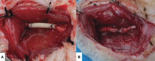
Twenty adult Sprague–Dawley rats weighing 200–250 g were used to evaluate nerve regeneration using the electrospinning-fabricated NCs. The animals were divided into 2 groups of 10 rats each. Rats in Group A (test group) received PLGA-SF NCs selected from the NC group showing the best alignment. Rats in group B (autograft controls) received autografts. All procedures adhered strictly to the guidelines of the Sichuan University Institutional Animal Care and Use Committee. Sciatic nerve defects (10 mm) were created by surgical removal of the nerve tissue. The distance from distal end of the defect to furcation of the sciatic nerve was 5 mm. The animals were anesthetized with 10% chloral hydrate (30 mg/100 g body weight) [Citation18]. An incision was made in the skin, and muscles around the nerve tissues were separated using blunt dissection to expose the right sciatic nerve. Subsequently, the right sciatic nerve was severed into proximal and distal segments at the center of the right thigh. NCs (12-mm length) were interposed between the proximal and the distal stumps, and the two stumps were sutured with 8-0 nylon to a depth of 1 mm into the conduits, leaving a 10-mm gap between the stumps, as shown in . The muscle layer was sutured with 3-0 silk sutures (Ethicon), and the skin was closed with 3-0 silk sutures [Citation17]. Each rat received a single implant, which was removed after 6 weeks. Penicillin (800,000 IU/kg) was administered after surgery as in intramuscular injection. After 6 weeks, histomorphometric evaluations were performed to evaluate the efficiency of nerve autografts and PLGA-SF NCs for nerve regeneration.
Figure 2. PLGA-SF NCs just after implantation (A) and six weeks after implantation (B).
The regenerated nerve specimens were fixed with a cold buffered 3% glutaraldehyde in 0.1 M PBS for 24 hours immediately after harvesting and were postfixed in 1% osmium tetraoxide for 2 hours. They were then dehydrated in a graded ethanol series, divided into two equivalent portions, and embedded in Epon 812 resin. The distal portions of the specimens were cut with an ultramicrotome (Leica Corporation, Germany) into thin cross-sections of 1-mm thickness, stained with toluidine blue, and observed using light microscopy. The average axonal diameter and myelin-sheath thickness in the regenerated nerves were estimated using an image analysis program (i-Solution, IMT, Korea) with the captured-light microscopy pictures. To observe more detailed axon and myelin sheath regeneration inside the tubes, the proximal ends of the specimens were also cut into ultrathin sections of 50- to 60-nm thickness. The sections were stained with lead citrate and uranyl acetate, and examined using a transmission electron microscope (TEM; Model H-7650, Hitachi, Japan).
Statistical Analysis
All numerical data are presented as mean ± standard deviation (SD). All results were subjected to statistical analysis using SPSS 16 software for Windows (student version). Statistically significant values were defined as P < 0.05, based on one-way analysis of variance (ANOVA) or two sample t-test
RESULTS AND DISCUSSION
Characterization of NCs Made from the PLGA- SF
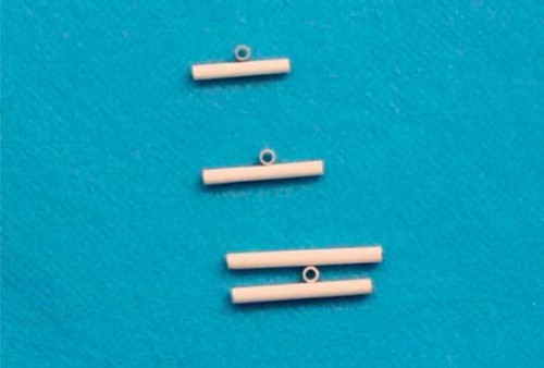
Macroscopic observation of two NCs showed internal diameters of 1.5 mm. As measured by a reading Vernier caliper, the external diameters were found to range from 2.0 to 2.3 mm. The NCs appeared uniform and non-woven, and had smooth surfaces ().
Figure 3. Macroscopic image of PLGA-SF NCs.
The mean diameter of the nanofiber was 593 nm when the throw distance was 10 cm. This was reduced to 334 nm when the throw distance was 15 cm. When the throw distance was fixed, varying the rotational velocity had no effect on the nanofiber diameter. At a throw distance of 15 cm, the mean nanofiber diameters were 305 nm at 2000 r/min, 319 nm at 1500 r/min, and 387 nm at 1000 r/min. There were no significant differences between the three groups (P > 0.05) when the nanofiber diameters were used in statistics analysis with ANOVA (). Similarly, there were no significant differences between the groups when the throw distance was 10 cm. Irrespective of the rotational velocity of the collecting mandrel, the nanofibers from electrospun NCs had many droplets and beads when the distance was 10 cm (). This may be because the throw length was too short, and the spurting solvent did not evaporate completely before arriving at the collector mandrel. At a distance of 15 cm, increases in the collector rotation velocity resulted in more orderly alignment and better orientation of the nanofibers (, , and ).
Table 1. Mean diameter of nanofiber under different distance and rotating velocity.
Figure 4. SEM of nanofibers from PLGA-SF NCs prepared at a distance of 10 cm. Note the high numbers of droplets and beads.
Figure 5. SEM of nanofibers from PLGA-SF NCs prepared at a throw distance of 15 cm and rotational velocity of 1000 r/min. Note the fraction of nanofibers aligned in sequence.
Figure 6. SEM of nanofibers from PLGA-SF NCs prepared at a throw distance of 15 cm and rotational velocity of 1500 r/min. The nanofibers show an orderly alignment and good orientation.
Figure 7. SEM of nanofibers from PLGA-SF NCs prepared at a throw distance of 15 cm and rotational velocity of 2000 r/min. Nanofibers exhibit an orderly alignment and good orientation, but a number of nanofibers are broken.
In addition, all the experiments were done under exposure to an ambient atmosphere, and as the rotational velocity increased, the airflow caused by the rotation of the collector made it difficult to tow the fiber yarn onto the collector. This limits the benefits that can be gained by increasing rotational velocity, and further work will be done in a vacuum environment. With increases in rotational speed, there is better alignment of the fibers and a reduction in the number of fibers in a yarn. The improved alignment in the fibers with increasing rotational speed is demonstrated in , , and . We also observed, however, that the fibers break when the rotational speed is too high.
We found the best alignment conditions for the manufacture of NCs to be at a throw distance of 15 cm with a rotational velocity of 1500 r/min. These conditions produced nanofibers with a mean diameter of 319 nm, and NCs with a porosity ratio of 90.1 ± 0.05% and tensile strength of 55 ± 0.06 Mpa. shows that network non-woven construction, uniform texture, and a smooth tube wall were observed for the NCs. SEM indicates a well-distributed porous structure in the NCs that were used for in vivo and vitro experiments.
Figure 8. Cross-section of the PLGA-SF NCs observed under SEM (A:100 × magnification, B:1000 × magnification).
Detached Schwann cells from neonatal rats grew well in the NCs. depicts micrographs of Schwann cells cultured for 3 days on PLGA-silk scaffold. The overall results indicate that Schwann cells attach well and exhibit normal phenotype and axonal outgrowth as revealed by immunostaining.
Figure 9. SEM micrographs of Schwann cells cultured on the scaffolds for 3 days.
The Food and Drug Administration has approved PLGA for use in a variety of biomedical applications. Electrospun PLGA nanofibrous scaffolds are well suited for promoting adhesion, migration, differentiation, and proliferation of PC12 nerve stem cells [Citation10]. Substrates made from silk fibroin exhibit high biocompatibility and have been shown to support Schwann cell growth, with no cytotoxicity or effects on the cell phenotype [Citation19].
Histological Assessment
In the course of the 6-week experiment there were no instances of nerve dislocation out of the NC in any animals, and 6 weeks after implantation the structure of the NC was well maintained (). This is an important factor for axon growth. The 10-mm gap removed by surgery was found to have been bridged by the regenerated tissue 6 weeks after the implantation. The vascularized surface of the NCs could be clearly observed. The regenerated nerves within the NCs were stained by toluidine blue to evaluate the number and diameters of regenerated axons in both conduit groups (). Numerous bundles of regenerated nerve fibers were clearly identified in the sections of the regenerated tissues (). Statistical analysis showed the average diameter of regenerated nerve fibers and the thickness of the regenerated myelin sheath were slightly, but significantly, larger for autograft controls than for NCs from PLGA-SF (P < 0.05; ), based on two sample t-test.
Figure 10. Cross-sections of regenerated nerves taken from an autograft and an NC implanted in a rat for 6 weeks. (A1). Autograft negative controls with toluidine blue staining (scale bar: 50 μm). (A2). PLGA-SF NC with toluidine blue staining (scale bar: 50 μm). (B1). Autograft negative control with transmission electron micrographs (scale bar: 1 μm). (B2). The PLGA-SF NC with transmission electron micrographs (scale bar: 1 μm).
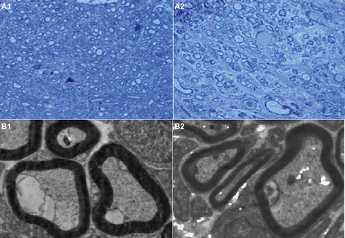
Figure 11. Plot showing the diameter of regenerated nerve fibers and thickness of regenerated myelin sheath. Results are mean ± SD for two grafts. (A: test group; B: autograft controls).
Transmission electron microscopy (TEM) of the mid-portion of the regenerated tissues revealed that formation of regenerated myelinated fibers occurred on both nerve conduits (). Similar to autograft controls, myelinated fibers of the regenerated tissues in the PLGA- SF NCs had a compact and uniform structure.
The Effect of the NC in Nerve Regeneration
To avoid the disadvantages associated with autografts, tissue-engineered artificial nerve conduits represent the best method for reconstructing injured nerves [Citation1]. Electrospinning is a versatile technique for producing sub-micron fibers that can be used to produce highly controllable, engineered tubular scaffolds for use as NCs to repair peripheral nerve transection injuries. Interest in employing electrospinning for scaffold fabrication is mainly due to the ease with which polymer composition and processing parameters can be manipulated to alter the mechanical, biological, and kinetic properties of the scaffold [Citation20]. Because electrospun scaffolds can mimic the architecture of the ECM and possess high surface-area-to-volume ratios that improve cell attachment, they are well suited to neural tissue engineering to enhance nerve regeneration. A few recent in-vitro studies have shown parallel neurite growth on various electrospun-aligned polymer fibers [Citation21, Citation22]. PLGA and SF have been used as NCs in previous studies because of their favorable biodegradability and biocompatibility [Citation10–12], and their effects on nerve regeneration have been encouraging [Citation16,Citation19,Citation23–25].
In this study, PLGA-SF NCs were electrospun to connect the proximal and the distal stumps in the severed right sciatic nerve of rats. Because the NCs were porous, they were permeable to nutrients and waste products, allowing cell growth within the structure. Since natural tissues or organs are nanometer in dimension, and cells interact directly with (and create) nanostructured ECMs, the biomimetic features and excellent physiochemical properties of nanomaterials play key roles in stimulating cell growth, as well as guiding tissue regeneration. Nanotechnology provides a wide platform for the development of novel and improved neural tissue-engineering materials and therapies, including the design of nanofiber/nanotube scaffolds with exceptional cytocompatibility and conductivity properties to support neuronal activities [Citation26–27]. Although histological assessment together with the results of TEM demonstrated that the effects nerve repair using NCs made from PLGA-SF were not better than autografts, the results demonstrate the use of PLGA-SF NCs indeed provides an alternative method for effectively bridging long-segment nerve defects of peripheral nerves.
CONCLUSIONS
NCs prepared from PLGA-SF were effective in repairing peripheral nerve damage in rats. Like autografts, PLGA-SF NCs can mimic the ECM architecture and foster cell attachment. Unlike autografts, PLGA-SF NCs offer the advantages of fabrication with different dimensions, degradation rates, mechanical properties, and microarchitectures. In addition, these synthetic NCs are not subject to the drawbacks of limited supply, permanent loss of nerve function at the donor site, morbidity at the donor site, and the need for multiple surgeries. Histological assessment together with TEM studies showed that functional recovery of the nerves using PLGA-SF NCs was similar to that seen with autografts. However, the overall results were not better than those using autologous nerve grafts in situ. This shows there is still a long way to go in developing an artificial nerve-bridging substitute for nerve grafts for the repair of peripheral nerve defects.
Declaration of interest: The authors report no conflicts of interest. The authors alone are responsible for the content and writing of the paper.
Related Research Data
REFERENCES
- Schnell, E., Klinkhammer, K., Balzer, S., Brook, G., Klee, D., Dalton, P., . (2007). Biomaterials 28:3012–25.
- Ruiter, G.C., Onyeneho, I.A., Liang, E.T., Moore, M.J., Knight, A.M., Malessy, M.J.A., . (2007). J Biomed Mater Res A 84(3):643–51.
- Ruiter, G.C.W., Malessy, M.J.A., Alaid, A.O., Spinner, R.J., Engelstad, J.K., Sorenson, E.J., . (2008). ExpNeurol 211(2):339–50.
- Ruiter, G.C., Spinner, R.J., Malessy, M.J.A., Moore, M.J., Sorenson, E.J., Currier, B.L., . (2008). Neurosurgery 63(1):144–55.
- Wang, S., Yaszemski, M.J., Knight, A.M., Gruetzmacher, J.A., Windebank, A.J., Lu, L. (2009). ActaBiomater 5(5):1531–42.
- Wang, S., Lu, L., Gruetzmacher, J.A., Currier, B.L., Yaszemski, M.J. (2006). Biomaterials 27(6):832–41.
- Huang, Y.C., Huang, Y.Y. (2006). Artif Organs 30:514–22.
- Kokai, L.E., Ghaznavi, A.M., Marra, K.G. (2010). Biomaterials 31:2313–22.
- Alluin, O., Wittmann, C., Marqueste, T., Chabas, J.F., Garcia, S., Lavaut, M.N., . (2009). Biomaterials 30:363–7
- Bini, T.B., Gao, S.J., Wang, S., Ramakrishna, S. (2006). Journal of Materials Science 41(19):6453–435.
- Nie, H.R., He, A.H., Jia, B., Wang, F., Jiang, Q.S., Han, C.C. (2010). Polymer 51:3344–8.
- Vollrath, F., Knight, D.P. (2001). Nature 410:541–8.
- Ashammakhi, N., Wimpenny, I., Nikkola, L., Yang, Y. (2009). J Biomed Nano-technology 5:1–19.
- Sofia, S., McCarthy, M.B., Gronowicz, G., Kaplan, D.L. (2001). J Biomed Mater Res 54:139–48.
- Min, B.M., Lee, G., Kim, S.H., Nam, Y.S., Lee, T.S., Park, W.H. (2004). Biomaterials 25:1289–97.
- Madduri, S., Papaloizos, M., Gander, B. (2010). Biomaterials 31:2323–34.
- Bian, Y.Z., Wang, Y., Aibaidoula, G., Chen, G.Q., Wu, Q. (2009). Biomaterials 30:217–225.
- Rustemeyer, J., Dicke, U. (2010). Int J Oral Maxillofac Surg 39:889–96.
- Yang, Y.M., Chen, X.M., Ding, F., Zhang, P.Y., Liu, J., Gu, X.S. (2007). Biomaterials 28:1643–1652.
- Chong, E.J., Phan, T.T., Lim, I.J., Zhang, Y.Z., Bay, B.H., Ramakrishna, S., . (2007). Acta Biomaterialia 3:321–30.
- Ghasemi-Mobarakeh, L., Prabhakaran, O.P., Morshed, M., Nasr-Esfahani, M.H., Ramakrishna, S. (2008). Biomaterials 29:4532–4539.
- Yao, L., O'Brien, N., Windebank, A., Pandit, A. (2009). J Biomed Mater Res B Appl Biomater 90:483–91.
- Liu, B., Cai, S.X., Ma, K.W., Xu, Z.L., Dai, X.Z., Yang, L., . (2008). J Mater Sci Mater Med 19:1127–32.
- Oh, S.H., Kim, J.H., Song, K.S., Jeon, B.H., Yoon, J.H., Seo, T.B., . (2008). Biomaterials 29:1601–9.
- Kalbermatten, D.F., Pettersson, J., Kingham, P.J., Pierer, G., Wiberg, M., Terenghi, G.J. (2009). Reconstr Microsurg 25:27–33.
- Zhang, Y.Z., Su, B., Venugopal, J., Ramakrishna, S., Lim, C.T. (2007). Int J Nanomedicine 2:623–38.
- Zhang, L.J., Webster, T.J. (2009). Nano Today 4:66–80.